US4062096A - Variable crown roll - Google Patents
Variable crown roll Download PDFInfo
- Publication number
- US4062096A US4062096A US05/756,416 US75641677A US4062096A US 4062096 A US4062096 A US 4062096A US 75641677 A US75641677 A US 75641677A US 4062096 A US4062096 A US 4062096A
- Authority
- US
- United States
- Prior art keywords
- sleeve
- arbor
- roll
- hydraulic fluid
- piston
- Prior art date
- Legal status (The legal status is an assumption and is not a legal conclusion. Google has not performed a legal analysis and makes no representation as to the accuracy of the status listed.)
- Expired - Lifetime
Links
Images
Classifications
-
- B—PERFORMING OPERATIONS; TRANSPORTING
- B21—MECHANICAL METAL-WORKING WITHOUT ESSENTIALLY REMOVING MATERIAL; PUNCHING METAL
- B21B—ROLLING OF METAL
- B21B27/00—Rolls, roll alloys or roll fabrication; Lubricating, cooling or heating rolls while in use
- B21B27/02—Shape or construction of rolls
- B21B27/03—Sleeved rolls
- B21B27/05—Sleeved rolls with deflectable sleeves
Definitions
- This invention relates to variable crown rolls for rolling mill stands. It is more particularly concerned with such rolls in which the variation of crown is accomplished within the roll.
- Backup rolls are commonly used in four-high mill stands for metal strip and the like to apply rolling pressure to smaller diameter work rolls. The latter tend to bow away from the work in the center when the large forces required for rolling are applied to the roll necks. To counteract this tendency, the roll stands are provided with larger diameter back-up rolls and the rolling forces are applied to the necks of those more rigid rolls which, in turn, transmit rolling pressure to the bodies of the work rolls. Even in four-high mill stands, however, some springing or bowing of the work rolls occurs, and it has been compensated for conventionally by grinding a crown on the backup rolls. Crowned rolls are of somewhat greater diameter in the middle than at the ends. A fixed crown, however, results in flat strip only for a single strip width and roll force.
- My invention comprises, briefly a mandrel and sleeve type roll having shoulders on the mandrel bearing on the ends of the sleeve and means for increasing the force with which those shoulders hold the sleeve against the mandrel simultaneously with increase in the force providing crown in the sleeve.
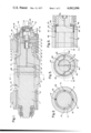
- FIG. 1 is a vertical longitudinal section through a first embodiment of a variable crown roll of my invention
- FIG. 2 is a cross section through the roll of FIG. 1 taken on the plane II--II of FIG. 1,
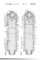
- FIG. 3 is a vertical longitudinal section through a second embodiment of a variable crown roll of my invention
- FIG. 4 is a vertical longitudinal section through a third embodiment of my invention.
- FIG. 5 is a cross section through the roll of FIG. 4 taken on the plane V--V of that figure, and
- FIG. 6 is a horizontal longitudinal section through a portion of the roll of FIG. 5 taken on the plane VI--VI of FIG. 5.
- the arbor 10 of my roll is provided with roll necks 11 and 12 at either end.
- Roll neck 11 is suitable for mounting in a conventional chock 13.
- Adjacent roll neck 11, arbor 10 is formed with a shoulder 15 having an inner face 16 which is undercut to a bevel.
- Surrounding roll neck 12 is a collar 19 the outer surface of which has the same contour and dimensions as the outer surface of roll neck 11 so that it is suitable for mounting in a conventional chock 14.
- Collar 19 is dimensioned to slide axially on roll neck 12, but is keyed thereto by keys 17 and 18 to prevent rotation between collar and roll neck.
- Collar 19 on its inner end adjacent the inner end of roll neck 12 is formed into a shoulder 20 similar to shoulder 15 and likewise having an inner face 21 which is undercut to a bevel.
- sleeve 22 Centrally mounted to arbor 10 is sleeve 22, between shoulders 15 and 20.
- Sleeve 22 has ends with chamfers or bevels 23 and 24 which fit into undercut faces 16 and 20 respectively.
- the inside surface of sleeve 22 is hollowed so as to form an annular cavity 25 which extends over the central portion of sleeve 22. Cavity 25 is vented to an end of sleeve 22 through passage 27 which is provided with a closure 28.
- a cylindrical filler 30 dimensioned to leave only a small unfilled gap between sleeve 22 and arbor 10.
- Filler 30 is conveniently constructed of four identical longitudinal sections 31 as is shown in FIG. 2. These are bolted together along alternate joints 32, leaving clearance between the other pair of joints 33.
- the hydraulic means for operating my apparatus are contained in cylinder 34 mounted at the outer end of collar 19.
- inner or clamping piston 35 and outer or crowning piston 36 Within cylinder 34 are inner or clamping piston 35 and outer or crowning piston 36.
- Inner piston 35 has a hollow piston rod 37 which extends through the inner end of cylinder 34 and is threaded into a tapped bore 26 in neck 12 of arbor 10.
- Outer piston 36 has a piston rod 38 which passes through inner piston 35 into the bore 29 of hollow piston rod 37.
- Hydraulic fluid is supplied to my roll through a rotary valve 40 on end cap 41 of cylinder 34. In one valve position the fluid passes through port 42 into cylinder 34 between outer piston 36 and the inner face of end cap 41.
- hydraulic fluid passes through a cross bore 43 in end cap 41 and longitudinal bore 44 in roll neck 20 into cylinder 34 at a point on the other side of piston 36 past which inner piston 35 can move.
- a connection between the inner end of cylinder 34 and the bore 29 of piston rod 37 is formed through a bore 39 in the inner face of outer piston 36, cross bore 45, axial bore 46 in piston 38 and check valve 47 opening out of the outer end of that piston.
- a passage 49 Opening from the inner end of bore 29 through roll neck 12 is a passage 49 which, through cross passage 50, connects with the cavity 25 in sleeve 22.
- a longitudinal bore 51 is provided through the wall of piston rod 37 from bore 29 of piston rod 37 at its inner end to the outer surface of piston rod 37 immediately adjacent the inner face of piston 35.
- Hydraulic fluid is introduced through rotary valve 40 and bores 43 and 44 into cylinder 34 between pistons 35 and 36.
- the fluid also passes through bore 39, bores 45 and 46 and check valve 47 into bore 29 of piston rod 37 and through passages 49 and 50 in arbor 10 into cavity 25.
- rotary valve 40 is switched so that the fluid is directed through port 42 against the outside face of piston 36.
- FIG. 3 A second embodiment of my invention is shown in FIG. 3. It is the same in most respects as that of FIGS. 1 and 2 described above and like parts carry the same reference characters as in FIGS. 1 and 2.
- the portion 52 of arbor 10 between shoulder 15 and the end of the cavity 25 tapers slightly outwardly toward shoulder 15.
- the inner surface 53 of that end of sleeve 22 is tapered in the same way.
- Shoulder 15 has a square end face 54.
- Shoulder 20 is formed with an annular tapered tongue 55 extending toward shoulder 15 and the corresponding end of sleeve 22 is formed with an annular tapered groove 56 therein which mates with tongue 55.
- An inclined bore 58 from the surface of tapered portion 52 of arbor 10 together with a meeting oppositely inclined bore 59 emerging from shoulder 15 is mounted at shoulder 15 with a closure 60, and axial bore 61 from the outer end of tapered tongue 55 meets a radial bore 62 in shoulder 20 and is provided at shoulder 20 with a closure 63.
- FIG. 3 The roll of FIG. 3 is assembled in the same way as that of the embodiment illustrated in FIGS. 1 and 2 and has its crown varied in the way previously described in connection with my first embodiment.
- the inside tapered end 53 of sleeve 22 seals against the tapered portion 52 of the arbor 10 as collar 19 is moved inwardly over roll neck 12.
- An auxiliary U-shaped filler ring 64 is placed between the collar 19 and the face of sleeve 22. This prevents the tongue 55 from seating into groove 56 while sleeve 22 seats on taper 52.
- the filler ring 64 is then removed, and tapered tongue 55 of shoulder 20 seals in groove 56 in the end of sleeve 22.
- liner 30 in both above described embodiments of my invention is to fill most of the cavity 25 between arbor 10 and sleeve 22 so as to minimize the quantity of hydraulic fluid required to fill the roll.
- the ratio between the sleeve thickness at its ends and at its center may be such that the volume of the cavity is substantial.
- FIGS. 4, 5 and 6 A third embodiment of my invention is shown in FIGS. 4, 5 and 6. It is similar in most respects to the apparatus of FIGS. 1 and 2 described herein, and like parts of the apparatus are identified by the same reference characters.
- annular cavity 25 in sleeve 22 is occupied by a cylindrical liner 65 which is joined by an annular weld 66 to the end of cavity 25 adjacent roll neck 11 and is joined by annular weld 67 to cavity 25 near its end adjacent roll neck 12.
- liner 65 may be inserted in cavity 25, that cavity is elongated to the end of sleeve 22 which adjoins roll neck 12.
- Liner 65 substantially fills cavity 25 except for a small gap or clearance space between the outside of liner 65 and the surface of cavity 25, which clearance space, however, is closed at each end by welds 66 and 67 above mentioned.
- Roll neck 12 is smaller in diameter than the body of arbor 10 and joins that body at an end of sleeve 22.
- Cross bore 50 is located in roll neck 12 at that junction, as is shown in FIG. 4.
- Each end of cross bore 50 is connected to a length of tubing 68 which is curved around roll neck 12 through an angle of 90° so that the other ends 69 of tubing lengths 68 lie on a diameter of the roll normal to the axis of cross bore 50, as is shown in FIG. 5.
- Those ends 69 are connected by elbows to longitudinal bores 70 in the end of liner 65, which bores extend through the weld 66 and open into the clearance space between liner 65 and sleeve 22--see FIG. 6.
- the outer surface of liner 65 is provided with shallow circumferential and longitudinal grooves 71 which connect with bores 70 and facilitate distribution of hydraulic fluid in the clearance space between sleeve 22 and liner 65.
Abstract
Description
Claims (14)
Priority Applications (1)
| Application Number | Priority Date | Filing Date | Title |
|---|---|---|---|
| US05/756,416 US4062096A (en) | 1977-01-03 | 1977-01-03 | Variable crown roll |
Applications Claiming Priority (1)
| Application Number | Priority Date | Filing Date | Title |
|---|---|---|---|
| US05/756,416 US4062096A (en) | 1977-01-03 | 1977-01-03 | Variable crown roll |
Publications (1)
| Publication Number | Publication Date |
|---|---|
| US4062096A true US4062096A (en) | 1977-12-13 |
Family
ID=25043376
Family Applications (1)
| Application Number | Title | Priority Date | Filing Date |
|---|---|---|---|
| US05/756,416 Expired - Lifetime US4062096A (en) | 1977-01-03 | 1977-01-03 | Variable crown roll |
Country Status (1)
| Country | Link |
|---|---|
| US (1) | US4062096A (en) |
Cited By (11)
| Publication number | Priority date | Publication date | Assignee | Title |
|---|---|---|---|---|
| US4191077A (en) * | 1978-12-26 | 1980-03-04 | Preston Engravers, Inc. | Bearing block with air supply passage |
| DE3109316A1 (en) * | 1980-03-11 | 1981-12-24 | Sumitomo Metal Industries, Ltd., Osaka | VARIABLE ROLLER |
| US4445349A (en) * | 1981-11-17 | 1984-05-01 | White Consolidated Industries, Inc. | Variable crown roll shape control systems |
| FR2563449A1 (en) * | 1984-04-25 | 1985-10-31 | Ishikawajima Harima Heavy Ind | Improvement to rolling-mill rolls |
| US4553296A (en) * | 1983-06-09 | 1985-11-19 | White Consolidated Industries, Inc. | Self-contained inflatable crown roll |
| US4553297A (en) * | 1984-03-29 | 1985-11-19 | White Consolidated Industries, Inc. | Hydro-mechanical inflatable crown roll |
| US4599770A (en) * | 1984-04-06 | 1986-07-15 | Ishikawajima-Harima Jukogyo Kabushiki Kaisha | Roll for rolling mill |
| US4683744A (en) * | 1985-06-18 | 1987-08-04 | Wean United Rolling Mills, Inc. | Flexible edge roll |
| US4691420A (en) * | 1985-08-09 | 1987-09-08 | J.M. Voith Gmbh | Stone pressure roll for a web of fibers |
| US5943895A (en) * | 1997-04-24 | 1999-08-31 | Sms Schloemann-Siemag Aktiengesellschaft | Dynamic crown control back-up roll assembly |
| US6398701B1 (en) * | 1996-12-20 | 2002-06-04 | Koenig & Bauer Aktiengesellschaft | Cylinder for a rotary press |
Citations (4)
| Publication number | Priority date | Publication date | Assignee | Title |
|---|---|---|---|---|
| US1630470A (en) * | 1922-08-24 | 1927-05-31 | Clifford Corp | Apparatus for breaking down ore bodies |
| US2970339A (en) * | 1957-09-12 | 1961-02-07 | John M Hausman | Calender roll having adjustable crown |
| US3457617A (en) * | 1966-01-19 | 1969-07-29 | Bwg Bergwetk Und Walzwerk Masc | Working roll for a roller mill |
| US3604086A (en) * | 1967-09-29 | 1971-09-14 | Siegener Maschinenbau Gmbh | Method and apparatus for compensating for the deflection of steel plate rolling mill rolls |
-
1977
- 1977-01-03 US US05/756,416 patent/US4062096A/en not_active Expired - Lifetime
Patent Citations (4)
| Publication number | Priority date | Publication date | Assignee | Title |
|---|---|---|---|---|
| US1630470A (en) * | 1922-08-24 | 1927-05-31 | Clifford Corp | Apparatus for breaking down ore bodies |
| US2970339A (en) * | 1957-09-12 | 1961-02-07 | John M Hausman | Calender roll having adjustable crown |
| US3457617A (en) * | 1966-01-19 | 1969-07-29 | Bwg Bergwetk Und Walzwerk Masc | Working roll for a roller mill |
| US3604086A (en) * | 1967-09-29 | 1971-09-14 | Siegener Maschinenbau Gmbh | Method and apparatus for compensating for the deflection of steel plate rolling mill rolls |
Cited By (11)
| Publication number | Priority date | Publication date | Assignee | Title |
|---|---|---|---|---|
| US4191077A (en) * | 1978-12-26 | 1980-03-04 | Preston Engravers, Inc. | Bearing block with air supply passage |
| DE3109316A1 (en) * | 1980-03-11 | 1981-12-24 | Sumitomo Metal Industries, Ltd., Osaka | VARIABLE ROLLER |
| US4445349A (en) * | 1981-11-17 | 1984-05-01 | White Consolidated Industries, Inc. | Variable crown roll shape control systems |
| US4553296A (en) * | 1983-06-09 | 1985-11-19 | White Consolidated Industries, Inc. | Self-contained inflatable crown roll |
| US4553297A (en) * | 1984-03-29 | 1985-11-19 | White Consolidated Industries, Inc. | Hydro-mechanical inflatable crown roll |
| US4599770A (en) * | 1984-04-06 | 1986-07-15 | Ishikawajima-Harima Jukogyo Kabushiki Kaisha | Roll for rolling mill |
| FR2563449A1 (en) * | 1984-04-25 | 1985-10-31 | Ishikawajima Harima Heavy Ind | Improvement to rolling-mill rolls |
| US4683744A (en) * | 1985-06-18 | 1987-08-04 | Wean United Rolling Mills, Inc. | Flexible edge roll |
| US4691420A (en) * | 1985-08-09 | 1987-09-08 | J.M. Voith Gmbh | Stone pressure roll for a web of fibers |
| US6398701B1 (en) * | 1996-12-20 | 2002-06-04 | Koenig & Bauer Aktiengesellschaft | Cylinder for a rotary press |
| US5943895A (en) * | 1997-04-24 | 1999-08-31 | Sms Schloemann-Siemag Aktiengesellschaft | Dynamic crown control back-up roll assembly |
Similar Documents
| Publication | Publication Date | Title |
|---|---|---|
| US4062096A (en) | Variable crown roll | |
| US3250542A (en) | Hydraulic chucks and arbors | |
| US4386566A (en) | Mandrel assembly for demountable printing cylinder | |
| US3831242A (en) | Rolling mill work roll assemblies | |
| US4422653A (en) | Chuck for tubular workpieces | |
| EP0963269B1 (en) | Hydromechanical chuck | |
| US3388916A (en) | Hydraulic arbor | |
| US4811962A (en) | Holder for machining thin walled cylinder | |
| US4683744A (en) | Flexible edge roll | |
| US4008598A (en) | Work reducing | |
| US3388917A (en) | Hydraulic chucks and arbors | |
| US4602408A (en) | Roll-stand roll with hydraulically changeable contour | |
| JP2539274B2 (en) | Method and device for fixing transmission member etc. on pipe | |
| US4383483A (en) | Hydraulically-actuated mandrel for a demountable printing cylinder | |
| EP0465742B1 (en) | Roll for a rolling mill | |
| US2722392A (en) | Connecting elements for a base and platform | |
| US3946584A (en) | Hydrostatic extrusion method and apparatus | |
| US2353774A (en) | Cylinder liner forcing mandrel | |
| US6532785B1 (en) | Method and apparatus for prefilling and hydroforming parts | |
| GB1584508A (en) | Work reducing and pressure applying apparatus | |
| SU1242271A1 (en) | Internal tools for cross roll mill | |
| JPS6148614A (en) | Oil film bearing | |
| US4173881A (en) | Rolling stand with hydraulic adjustment of the mill rolls | |
| JP2827541B2 (en) | Roll for rolling mill | |
| GB2137140A (en) | Printing Cylinders |
Legal Events
| Date | Code | Title | Description |
|---|---|---|---|
| STCF | Information on status: patent grant |
Free format text: PATENTED FILE - (OLD CASE ADDED FOR FILE TRACKING PURPOSES) |
|
| AS | Assignment |
Owner name: BLAW-KNOX COMPANY Free format text: MERGER;ASSIGNORS:AETNA-STANDARD ENGINEERING COMPANY;BLAW-KNOX CONSTRUCTION EQUIPMENT, INC.,;BLAW-KNOX EQUIPMENT, INC.;AND OTHERS;REEL/FRAME:003926/0382 Effective date: 19781221 Owner name: WHITE CONSOLIDATED INDUSTRIES, INC. Free format text: MERGER;ASSIGNORS:BLAW-KNOX COMPANY;KELVINATOR, INC.;WHITE-WESTINGHOUSE CORPORATION;AND OTHERS;REEL/FRAME:003926/0372 Effective date: 19781221 |
|
| AS | Assignment |
Owner name: BLAW KNOX CORPORATION, ONE OLIVER PLAZA, PITTSBURG Free format text: ASSIGNMENT OF ASSIGNORS INTEREST. EFFECTIVE SEPT. 27, 1985;ASSIGNOR:WHITE CONSOLIDATED INDUSTRIES, INC., A CORP OF DE.;REEL/FRAME:004532/0913 Effective date: 19851017 |
|
| AS | Assignment |
Owner name: ITALIMPIANTI OF AMERICA INCORPORATED (ITALIMPIANTI Free format text: ASSIGNMENT OF ASSIGNORS INTEREST. EFFECTIVE JUNE 30, 1987;ASSIGNOR:BLAW KNOX CORPORATION;REEL/FRAME:004936/0554 Effective date: 19870626 |