US4047088A - Dual voltage charging system - Google Patents
Dual voltage charging system Download PDFInfo
- Publication number
- US4047088A US4047088A US05/694,158 US69415876A US4047088A US 4047088 A US4047088 A US 4047088A US 69415876 A US69415876 A US 69415876A US 4047088 A US4047088 A US 4047088A
- Authority
- US
- United States
- Prior art keywords
- voltage
- battery
- controlled rectifier
- junction
- power supply
- Prior art date
- Legal status (The legal status is an assumption and is not a legal conclusion. Google has not performed a legal analysis and makes no representation as to the accuracy of the status listed.)
- Expired - Lifetime
Links
Images
Classifications
-
- H—ELECTRICITY
- H02—GENERATION; CONVERSION OR DISTRIBUTION OF ELECTRIC POWER
- H02J—CIRCUIT ARRANGEMENTS OR SYSTEMS FOR SUPPLYING OR DISTRIBUTING ELECTRIC POWER; SYSTEMS FOR STORING ELECTRIC ENERGY
- H02J7/00—Circuit arrangements for charging or depolarising batteries or for supplying loads from batteries
- H02J7/14—Circuit arrangements for charging or depolarising batteries or for supplying loads from batteries for charging batteries from dynamo-electric generators driven at varying speed, e.g. on vehicle
- H02J7/1423—Circuit arrangements for charging or depolarising batteries or for supplying loads from batteries for charging batteries from dynamo-electric generators driven at varying speed, e.g. on vehicle with multiple batteries
-
- Y—GENERAL TAGGING OF NEW TECHNOLOGICAL DEVELOPMENTS; GENERAL TAGGING OF CROSS-SECTIONAL TECHNOLOGIES SPANNING OVER SEVERAL SECTIONS OF THE IPC; TECHNICAL SUBJECTS COVERED BY FORMER USPC CROSS-REFERENCE ART COLLECTIONS [XRACs] AND DIGESTS
- Y02—TECHNOLOGIES OR APPLICATIONS FOR MITIGATION OR ADAPTATION AGAINST CLIMATE CHANGE
- Y02T—CLIMATE CHANGE MITIGATION TECHNOLOGIES RELATED TO TRANSPORTATION
- Y02T10/00—Road transport of goods or passengers
- Y02T10/60—Other road transportation technologies with climate change mitigation effect
- Y02T10/70—Energy storage systems for electromobility, e.g. batteries
-
- Y—GENERAL TAGGING OF NEW TECHNOLOGICAL DEVELOPMENTS; GENERAL TAGGING OF CROSS-SECTIONAL TECHNOLOGIES SPANNING OVER SEVERAL SECTIONS OF THE IPC; TECHNICAL SUBJECTS COVERED BY FORMER USPC CROSS-REFERENCE ART COLLECTIONS [XRACs] AND DIGESTS
- Y10—TECHNICAL SUBJECTS COVERED BY FORMER USPC
- Y10S—TECHNICAL SUBJECTS COVERED BY FORMER USPC CROSS-REFERENCE ART COLLECTIONS [XRACs] AND DIGESTS
- Y10S320/00—Electricity: battery or capacitor charging or discharging
- Y10S320/25—Optical coupler
Definitions
- This invention relates to motor vehicle electrical systems and more particularly to a motor vehicle electrical system that is capable of supplying both 12 volt and 24 volt loads.
- Motor vehicle electrical systems have one or more batteries and an engine driven generator for supplying charging current to the batteries and to the electrical loads on the vehicle.
- an engine driven generator for supplying charging current to the batteries and to the electrical loads on the vehicle.
- 24 volt loads are the electric cranking motor for cranking the engine and various 24 volt direct current blower motors.
- Examples of 12 volt loads are the outside lighting system for the vehicle such as head lamps and 12 volt communication equipment.
- One known arrangement for supplying 12 and 24 volt loads is to connect two 12 volt batteries in series across the output of a generating system which is regulated to provide the required voltage for charging the two series-connected batteries.
- the output of the generator system may be regulated, for example at 27.5 volts, and the two series-connected batteries are connected directly across this charging source.
- the 24 volt loads are connected across the two series-connected batteries while the 12 volt loads are connected across one of the 12 volt batteries.
- the present invention is an improvement over the battery charging systems described in the above-mentioned patents.
- the present invention contemplates providing a simple and inexpensive arrangement for maintaining equal charge on two series connected 12 volt batteries in a 12- ⁇ volt system.
- This is accomplished by providing an auxiliary charging circuit for one of the 12 volt batteries that includes a single controlled rectifier connected between one of the phase windings of the generator and the junction of the two batteries.
- the controlled rectifier is gated conductive whenever the voltage at the junction between batteries drops below substantially one-half the voltage applied to the 24 volt loads.
- This auxiliary charging circuit includes an inductance which serves to limit current flow to the 12 volt system and which also serves to minimize sudden load changes on the alternator phase windings when the battery of the 12 volt system is to be charged.
- Another object of this invention is to provide a 12-24 motor vehicle electrical system in which a controlled rectifier is connected between an alternator phase winding and a junction of the two 12 volt batteries and where the controlled rectifier is, at times, gated into conduction by a control circuit that includes optical coupling between the control circuit and the device for gating the controlled rectifier conductive.
- the gate of the controlled rectifier is connected to an optically gated controlled rectifier which is optically coupled to a light emitting diode.
- the light emitting diode is energized by the output of an operational amplifier which operates as a voltage comparator that has its input terminals connected to respond to the difference in voltage between one-half system voltage and the voltage of the junction of the two 12 volt batteries. Since optical coupling is utilized the power and control circuits of the system are electrically isolated to prevent feedback to the input of the operational amplifier.
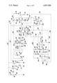
- FIGURE drawing is a schematic circuit diagram of a motor vehicle electrical system made in accordance with this invention.
- the reference number 10 generally designates an alternating current generator which has a field winding 12 and a three-phase Y-connected output winding comprised of phase windings 14, 16 and 18.
- the generator has a rotor (not illustrated) which is driven by theengine of the motor vehicle.
- the output winding of the generator is connected with the AC input terminals 20, 22 and 24 of a three-phase full wave bridge rectifier generally designated by reference number 26.
- This bridge rectifier is comprised of silicon diodes 28 having their cathodes connected to a positive direct voltage output terminal 30 and a plurality of silicon diodes 32 having their anodes commonly connected to the negative direct voltage output terminal 34 which is grounded.
- the positive direct voltage output terminal 30 is connected to a power supply conductor 36 which in turn is connected to junction 38.
- a pair of batteries 40 and 42 are connected in series between junction 38 and ground.
- the negative terminal of battery 40 is connected to the positive terminal of battery 42 by conductor 43.
- a junction 44 is connected to conductor 43 and therefore is connected to the positive terminal of battery 40 and the negative terminalof battery 42.
- the batteries 40 and 42 have equal rated terminal voltages of 12 volts and, as will be more fully described hereinafter, the output voltage of the generator 10 is regulated so as to provide a charging voltage between positive output terminal 30 and negative output terminal 34 of approximately 27.5 volts. This corresponds to the normal charging voltage for a so-called 24 volt system.
- the system is capable of supplying both 12 volt and 24 volt electrical loads on the vehicle.
- the 24 volt loads are represented by resistor 46 and are energized whenever switch 48 is closed.It is seen that the 24 volt loads 46, when energized, are connected betweenjunction 38 and ground. Examples of 24 volt loads that might be found on a motor vehicle are a 24 volt cranking motor for cranking the engine and other devices such as 24 volt direct current motors for operating blowers.Of course each load will have a separate switch for selectively energizing the respective load, which have not been illustrated.
- the 12 volt loads on the motor vehicle are represented as resistor 50. These loads can be energized whenever a switch 54 is closed it being understood that there are separate switches to selectively energize particular 12 volt loads.
- the 12 volt loads include the exterior lights on the vehicle such as the head lamps and other 12 volt operated accessories on the vehicle for example radio communication equipment. Regardless of the 12 volt load it is supplied between junction 44 and ground whenever a 12 volt load is energized.
- the system that has been thus far described is capable of charging the batteries 40 and 42 in series from direct voltage output terminals 30 and 34 of the bridge rectifier 26.
- the voltage between junction 38 and ground is maintained at a voltage of approximately 27.5 volts by a generator voltage regulator generally designated by reference numeral 56.
- the regulator can take various forms and can be of the type disclosed in the U.S. Pat. to Raver et al., No. 3,129,378, granted on Apr. 14, 1964.
- the regulator is disclosed herein as a simplified version of the one disclosed in the Raver et al. U.S. Pat. No. 3,129,378.
- the regulator 56 is of the transistor type and comprises a PNP transistor 58 connected in series with field winding 12. It is seen that the series combination of the emitter and collector electrodes of transistor 58 and field winding 12 are connected between conductor 60 and ground.
- the conductor 60 is connected with junction 38 so that it has a potential corresponding to the voltage at the positive side of battery 40.
- transistor 58 The conduction of transistor 58 is controlled by another PNP transistor 62 having its collector connected to the base of transistor 58.
- the base of transistor 62 is connected to one side of a Zener diode 64, the opposite side of which is connected to junction 66.
- the junction 66 is located between voltage divider resistors 68 and 70 which are series connected between conductor 60 and ground and therefore sense the voltage appearing between junction 38 and ground which is used to energize the 24 volt loads.
- the regulator has a disconnect feature which prevents current drain from the battery when the system is shut down. This feature is disclosed herein as an NPN transistor 72 having its collector and emitter circuit connected between resistor 74 and ground.
- transistor 72 The base of transistor 72 is connected with a conductor 76 which in turn is connected to junction 38 whenever a manually operable switch 78 is closed.
- switch 78 When switch 78 is closed transistor72 is biased conductive to connect one end of resistor 74 to ground. This is more fully explained in the above-mentioned Raver et al. U.S. Pat. No. 3,129,378 and as pointed out therein two parallel connected transistors may be used instead of one transistor 72.
- transistor 58 When the voltage between conductor 60 and ground, which is the sensed voltage between junction 38 and ground, exceeds a predetermined value the transistor 58 is switched off due to the fact that transistor 62 is biasedconductive. When the voltage drops below the desired regulated value transistor 62 switches off causing transistor 58 to turn on.
- the on-off switching of transistor 58 regulates the average value of the current supplied to field winding 12 with the result that the voltage appearing between conductor 38 and ground is maintained at a desired regulated value, for example 27.5 volts in a 24 volt system.
- the specific configuration of the voltage regulator forms no part of this invention andcould take other forms as long as it is capable of regulating the field current of the generator such that a desired regulated voltage is applied between junction 38 and ground to supply the 24 volt part of the system.
- the present invention includes an auxiliary charging circuit for charging battery 42.
- This auxiliary charging circuit is connected between junction 80 and junction 44. It is seen that the junction 80 is connected to one end of phase winding 18 and is also connected to the cathode of one of the diodes 32 and the anode of one of the diodes 28.
- This charging circuit includes a protective overloadcircuit breaker 82, a choke coil or inductor 84, the anode and cathode of asilicon controlled rectifier 86 and the conductor 90.
- a charging circuit can be traced from the end of phase winding 18 connected to junction 80, through circuit breaker 82, through inductor 84, through the anode-cathode circuitof controlled rectifier 86, through conductor 90 to junction 44, through battery 42 to ground and then through a diode 32 to, for example, phase winding 14 and then to the opposite side of phase winding 18.
- Current is only supplied through this circuit when the voltage induced in phase winding 18 is positive at its end connected to junction 80 with respect tovoltage at the ends of the other phase windings.
- the voltage at junction 80periodically goes negative as is known to those skilled in the art.
- the controlled rectifier 86 is only gated conductive when the voltage at junction 44 is less than substantially one-half the voltage between junction 38 and ground.
- a control circuit is provided which senses the voltage at junction 44 and a voltage which is substantially one-half the voltage appearing between conductor 38 and ground.
- the voltage at junction 44 is sensed by conductor 92 which is connected therewith.
- the voltage which represents substantially one-half system voltage is provided by a voltage divider comprised of resistors 94 and 96 and a potentiometer resistor 98. This voltage divider is connected betweena conductor 100 and a grounded conductor 102. It is seen that conductor 100is connected with junction 38 so that the voltage divider 94, 98 and 96 is connected between junction 38 and ground.
- the adjustable tap 104 of the voltage divider is adjusted such that its voltage equal substantially one-half the voltage appearing between junction 38 and ground.
- the system operates to gate controlled rectifier 86 conductive when the voltage at junction 44 is lower than one-half system voltage which appearsat tap point or junction 104.
- a semiconductor operational amplifier 106 connected to operate as a voltage comparator.
- This operational amplifier may be, for example, a Raytheon RA 4136 type which is available in a quad package. One of the four operational amplifiers of the package is used.
- One of the inputs to the operational amplifier is connected to tap 104 by aresistor 108.
- the other input to the operational amplifier is connected to conductor 92 through a resistor 110.
- the resistors 108 and 110 may have equal values of approximately 4700 ohms.
- the direct voltage power supply to the operational amplifier is provided by conductor 112 and conductor 113 which is grounded.
- the conductor 112 is connected with the collector of a PNP transistor 114.
- the transistor 114, together with the NPN transistor 116 and resistors 118, l20 and 122 form a semiconductor switch for applying the direct voltage on conductor 100 to the positive voltage input of the operational amplifier 106 whenever switch 78 is closed.
- the operational amplifier 106 With the connection of the operational amplifier 106, as shown in the drawing, it operates as a voltage comparator to compare the voltages of junction 44 and tap 104 and provide an output through resistor 124 to conductor 126 when the voltage at junction 44 is lower than one-half system voltage at tap 104 by a predetermined amount.
- the voltage of junction 44 is applied to one input of the operational amplifier 106 and the voltage of tap 104 is applied to the other input of the operational amplifier and the amplifier compares these voltages.
- the output of operational amplifier 106 is applied to a light emitting diode 128 having its anode connected to conductor 126 and its cathode connected to conductor 129.
- the light emitting diode is part of an optically coupled system for gating a second photo or light activated controlled rectifier 130 conductive whenever the light emitting diode 128 is energized by the output of operational amplifier 106.
- the photo-controlled rectifier 130 is of a typewhich is gated conductive when it is subjected to light energy from the light emitting diode 128.
- the physical arrangement of light emitting diode128 and controlled rectifier 130 is such that light energy developed by diode 128 is applied to a part of the controlled rectifier 130 that responds to the light energy.
- One type of device that includes the light emitting diode and controlled rectifier in one package, which is suitable for this purpose is the General Electric H11C2 Opto-Isolator.
- the anode of the light energy responsive controlled rectifier 130 is connected to junction 132 through a resistor 134.
- the cathode of controlled rectifier 130 is connected with the gate of controlled rectifier 86 through a conductor 136.
- the gate and cathode of controlled rectifier 130 is paralleled by a resistor 138.
- a resistor 140 and capacitor 142 are connected across the gate and cathode of controlled rectifier 86.
- the light energy responsive controlled rectifier 130 When the light emitting diode 128 is energized the light energy responsive controlled rectifier 130 is triggered conductive between its anode and cathode. This supplies the voltage at the junction 132 to the gate of the controlled rectifier 86 through the anode-cathode circuit of controlled rectifier 130 with the result that controlled rectifier 86 is biased conductive when the voltage at junction 132 is sufficiently positive, withrespect to the voltage of junction 44.
- the voltage at junction 80 which is connected to one end of phase winding 18, is an alternating voltage so that this junction goes positive and negative at the frequency of the voltage induced in the phase winding 18.
- the voltage wave form appearing between junction 80 and ground, when controlled rectifier 86 is conducting, is comprised of a series of spaced substantially square-wave direct voltage pulses since junction 80 periodically goes positive and negative and controlled rectifier 86 can only conduct when its anode is positive with respect to its cathode.
- the amplitude of these pulses is dictated by the output voltage of the generator which is controlled by voltage regulator 56.
- voltage pulses of a peak amplitude of approximately 27.5 volts are developed at junction 80, assuming that the voltage regulator is maintaining substantially 27.5 volts between junction 38 and ground.
- the control circuit includes Zener diodes 144 and 146 connected back to back between conductors 100 and 102 and Zener diodes 148 and 150 connectedback to back between conductor 92 and grounded conductor 102.
- the purpose of these Zener diodes is to clip transient voltages of either polarity.
- the Zener diodes 144 and 148 may have a break down voltage rating of 36 volts whereas the Zener diode 146 may have a voltage break down rating of 33 volts and the Zener diode 150 a voltage break down rating of 22 volts.
- the capacitor 152 connected between conductors 100 and 102 and capacitor 154 connected between conductors 92 and 102 are filter capacitors and may have a capacitance, for example, of 10 microfarads.
- a load resistor 160 ofapproximately 2200 ohms is connected between conductors 92 and 102.
- the switch 78 may be the run-switch and switch 78 is closed when the engine of the motor vehicle is started to drive the generator 10. This biases transistor 72 conductive to set the regulator 56 into operation and also biases the transistor 114 conductive to apply direct voltage to the operational amplifier 106.
- the operational amplifier 106 produces an output which energizes lightemitting diode 128.
- the energization of light emitting diode 128 causes light actuated controlled rectifier 130 to conduct between anode and cathode which in turn periodically gates controlled rectifier 86 conductive.
- the controlled rectifier 86 now supplies charging current pulses to the junction 44.
- the voltage at junction 80 is an alternating voltage with the result that this voltage causes controlled rectifier 86 to be gated on and off at the frequency of the voltage at junction 80 so that periodically occurring pulses of current are supplied to junction 44 and battery 42.
- the controlled rectifier 86 continuously switches on and off until the voltage of junction 44 is raised to a potential substantially equal to the voltage oftap 104 which occurs when the voltage at junction 44 equals substantially one-half system voltage. The system now reverts back to a mode of operation where the output voltage of bridge rectifier 26 is the sole supply of current to series connected batteries 40 and 42. Regardless of whether controlled rectifier 86 is biased conductive the voltage regulator56 tends to maintain a constant regulated voltage between junction 38 and ground.
- the choke coil 84 may be of the air core type and have an inductance of approximately 40 microhenrys. The purpose of the inductance 84 is to prevent sudden unbalance of current generated in the phase windings 14, 16and 18 when controlled rectifier 86 is gated conductive.
- the coil 84 also provides a small voltage drop in the circuit connecting junctions 80 and 44 and this voltage drop increases with the operating speed of the generator since the output frequency of the generator increases with increasing speed.
- the generator may have a capacity sufficient to provide current in the 100 amp range through choke 84, when controlled rectifier 86 is conducting, and the circuit breaker 82 may havean opening current rating of 105 amps.
- controlled rectifier86 is nonconductive. This is the same type of operation as when the voltages of junctions 44 and 104 are substantially equal. In summary, the only time controlled rectifier 86 is periodically triggered conductive is when the voltage at junction 44 is less than the voltage of tap or junction 104.
Priority Applications (2)
| Application Number | Priority Date | Filing Date | Title |
|---|---|---|---|
| US05/694,158 US4047088A (en) | 1976-06-09 | 1976-06-09 | Dual voltage charging system |
| CA273,273A CA1057821A (fr) | 1976-06-09 | 1977-03-07 | Circuit electrique pour vehicule automobile |
Applications Claiming Priority (1)
| Application Number | Priority Date | Filing Date | Title |
|---|---|---|---|
| US05/694,158 US4047088A (en) | 1976-06-09 | 1976-06-09 | Dual voltage charging system |
Publications (1)
| Publication Number | Publication Date |
|---|---|
| US4047088A true US4047088A (en) | 1977-09-06 |
Family
ID=24787644
Family Applications (1)
| Application Number | Title | Priority Date | Filing Date |
|---|---|---|---|
| US05/694,158 Expired - Lifetime US4047088A (en) | 1976-06-09 | 1976-06-09 | Dual voltage charging system |
Country Status (2)
| Country | Link |
|---|---|
| US (1) | US4047088A (fr) |
| CA (1) | CA1057821A (fr) |
Cited By (27)
| Publication number | Priority date | Publication date | Assignee | Title |
|---|---|---|---|---|
| US4090122A (en) * | 1977-03-10 | 1978-05-16 | Power Systems Development Corp. | Dual battery charger with logic means |
| US4179647A (en) * | 1977-12-02 | 1979-12-18 | General Motors Corporation | Dual output battery charging system |
| US4281277A (en) * | 1979-08-10 | 1981-07-28 | General Motors Corporation | Dual secondary cell charging system |
| US4403279A (en) * | 1981-11-02 | 1983-09-06 | J. I. Case Company | Vehicular plural voltage system |
| US4467265A (en) * | 1981-01-15 | 1984-08-21 | Wide-Lite International Corporation | Battery charger |
| US4491779A (en) * | 1983-10-12 | 1985-01-01 | General Motors Corporation | Motor vehicle electrical system |
| US4492912A (en) * | 1983-01-12 | 1985-01-08 | General Motors Corporation | Dual voltage motor vehicle electrical system |
| US4604528A (en) * | 1984-01-10 | 1986-08-05 | Peter Norton | Dual voltage power supply system for vehicles |
| US4672294A (en) * | 1986-01-24 | 1987-06-09 | Peter Norton | Dual battery system with improved overvoltage protection |
| US4686442A (en) * | 1986-04-28 | 1987-08-11 | General Motors Corporation | Dual voltage electrical system |
| US4694238A (en) * | 1984-01-10 | 1987-09-15 | Peter Norton | Dual voltage power supply system for vehicles |
| US4743830A (en) * | 1987-01-20 | 1988-05-10 | General Motors Corporation | Dual voltage electrical system |
| EP0282033A2 (fr) * | 1987-03-12 | 1988-09-14 | Globe-Union Inc. | Alternateur polyphasé et système de charge de batterie bitension pour récepteurs à tensions multiples |
| US4949028A (en) * | 1988-10-18 | 1990-08-14 | Sure Power, Inc. | Multiple voltage battery charge balancing and load protecting device |
| US4963813A (en) * | 1988-12-02 | 1990-10-16 | C. E. Niehoff & Co. | Control providing progressive charging in a dual voltage charging system |
| US4967136A (en) * | 1989-09-25 | 1990-10-30 | Prestolite Electric Incorporated | Battery equalization circuit for a dual voltage charging system |
| WO1991005395A1 (fr) * | 1989-10-07 | 1991-04-18 | Robert Bosch Gmbh | Dispositif d'equilibrage de la tension de charge d'un reseau de distribution de bord |
| US5013991A (en) * | 1989-04-27 | 1991-05-07 | Sure Power, Inc. | Multi-voltage alternator with integral bank switched bridge |
| US5164655A (en) * | 1991-08-05 | 1992-11-17 | Dimensions Unlimited, Inc. | 12-24 volt power system |
| US5479083A (en) * | 1993-06-21 | 1995-12-26 | Ast Research, Inc. | Non-dissipative battery charger equalizer |
| US6476571B1 (en) * | 1999-03-11 | 2002-11-05 | Toyota Jidosha Kabushiki Kaisha | Multiple power source system and apparatus, motor driving apparatus, and hybrid vehicle with multiple power source system mounted thereon |
| US20040164716A1 (en) * | 2003-01-17 | 2004-08-26 | Walter Richard T. | Generator with dual cycloconverter for 120/240 VAC operation |
| US20050118465A1 (en) * | 2003-12-02 | 2005-06-02 | Doob Llc | Multiple voltages DC battery power supply system |
| US20070170780A1 (en) * | 2004-08-26 | 2007-07-26 | Abb Schweiz Ag | Device for the feeding of auxiliary operating facilities for a fuel-electrically driven vehicle |
| US20070273336A1 (en) * | 2006-05-26 | 2007-11-29 | Windward Engineering, Llc | Dual voltage switching in power generation |
| US8957623B2 (en) | 2011-03-16 | 2015-02-17 | Johnson Controls Technology Company | Systems and methods for controlling multiple storage devices |
| CN105449794A (zh) * | 2016-01-07 | 2016-03-30 | 安徽江淮汽车股份有限公司 | 一种蓄电池充电控制电路及其方法 |
Citations (9)
| Publication number | Priority date | Publication date | Assignee | Title |
|---|---|---|---|---|
| US3011115A (en) * | 1960-10-31 | 1961-11-28 | Jr Charles B Grady | Solid state regulated battery charging system |
| US3624480A (en) * | 1970-11-12 | 1971-11-30 | Gen Motors Corp | Dual battery charger having dual output |
| US3667025A (en) * | 1971-06-21 | 1972-05-30 | Gen Motors Corp | Dual voltage system |
| US3671843A (en) * | 1971-05-05 | 1972-06-20 | Gen Motors Corp | Dual voltage charging system |
| US3710226A (en) * | 1971-03-25 | 1973-01-09 | Eltra Corp | Generator with multiple voltage regulators |
| US3809995A (en) * | 1970-11-19 | 1974-05-07 | Eltra Corp | Multiple output alternator |
| US3836788A (en) * | 1973-06-28 | 1974-09-17 | Gen Motors Corp | Internal combustion engine cranking motor circuit |
| US3900784A (en) * | 1974-07-10 | 1975-08-19 | Eltra Corp | Converter for battery charger |
| US3922592A (en) * | 1974-03-18 | 1975-11-25 | Eltra Corp | Four-phase alternator battery charger |
-
1976
- 1976-06-09 US US05/694,158 patent/US4047088A/en not_active Expired - Lifetime
-
1977
- 1977-03-07 CA CA273,273A patent/CA1057821A/fr not_active Expired
Patent Citations (9)
| Publication number | Priority date | Publication date | Assignee | Title |
|---|---|---|---|---|
| US3011115A (en) * | 1960-10-31 | 1961-11-28 | Jr Charles B Grady | Solid state regulated battery charging system |
| US3624480A (en) * | 1970-11-12 | 1971-11-30 | Gen Motors Corp | Dual battery charger having dual output |
| US3809995A (en) * | 1970-11-19 | 1974-05-07 | Eltra Corp | Multiple output alternator |
| US3710226A (en) * | 1971-03-25 | 1973-01-09 | Eltra Corp | Generator with multiple voltage regulators |
| US3671843A (en) * | 1971-05-05 | 1972-06-20 | Gen Motors Corp | Dual voltage charging system |
| US3667025A (en) * | 1971-06-21 | 1972-05-30 | Gen Motors Corp | Dual voltage system |
| US3836788A (en) * | 1973-06-28 | 1974-09-17 | Gen Motors Corp | Internal combustion engine cranking motor circuit |
| US3922592A (en) * | 1974-03-18 | 1975-11-25 | Eltra Corp | Four-phase alternator battery charger |
| US3900784A (en) * | 1974-07-10 | 1975-08-19 | Eltra Corp | Converter for battery charger |
Cited By (43)
| Publication number | Priority date | Publication date | Assignee | Title |
|---|---|---|---|---|
| US4090122A (en) * | 1977-03-10 | 1978-05-16 | Power Systems Development Corp. | Dual battery charger with logic means |
| US4179647A (en) * | 1977-12-02 | 1979-12-18 | General Motors Corporation | Dual output battery charging system |
| US4281277A (en) * | 1979-08-10 | 1981-07-28 | General Motors Corporation | Dual secondary cell charging system |
| US4467265A (en) * | 1981-01-15 | 1984-08-21 | Wide-Lite International Corporation | Battery charger |
| US4403279A (en) * | 1981-11-02 | 1983-09-06 | J. I. Case Company | Vehicular plural voltage system |
| US4492912A (en) * | 1983-01-12 | 1985-01-08 | General Motors Corporation | Dual voltage motor vehicle electrical system |
| US4491779A (en) * | 1983-10-12 | 1985-01-01 | General Motors Corporation | Motor vehicle electrical system |
| EP0137756A2 (fr) * | 1983-10-12 | 1985-04-17 | General Motors Corporation | Système électrique pour véhicule motorisé |
| EP0137756A3 (fr) * | 1983-10-12 | 1986-01-08 | General Motors Corporation | Système électrique pour véhicule motorisé |
| US4694238A (en) * | 1984-01-10 | 1987-09-15 | Peter Norton | Dual voltage power supply system for vehicles |
| US4604528A (en) * | 1984-01-10 | 1986-08-05 | Peter Norton | Dual voltage power supply system for vehicles |
| WO1989007359A1 (fr) * | 1984-01-10 | 1989-08-10 | Peter Norton | Alimentation en courant a tension simple ou double pour vehicule, a commutateur ameliore |
| US4672294A (en) * | 1986-01-24 | 1987-06-09 | Peter Norton | Dual battery system with improved overvoltage protection |
| US4686442A (en) * | 1986-04-28 | 1987-08-11 | General Motors Corporation | Dual voltage electrical system |
| US4743830A (en) * | 1987-01-20 | 1988-05-10 | General Motors Corporation | Dual voltage electrical system |
| EP0282033A2 (fr) * | 1987-03-12 | 1988-09-14 | Globe-Union Inc. | Alternateur polyphasé et système de charge de batterie bitension pour récepteurs à tensions multiples |
| US4816736A (en) * | 1987-03-12 | 1989-03-28 | Globe-Union Inc. | Polyphase alternator and dual voltage battery charging system for multiple voltage loads |
| EP0282033A3 (fr) * | 1987-03-12 | 1989-12-27 | Globe-Union Inc. | Alternateur polyphasé et système de charge de batterie bitension pour récepteurs à tensions multiples |
| US4949028A (en) * | 1988-10-18 | 1990-08-14 | Sure Power, Inc. | Multiple voltage battery charge balancing and load protecting device |
| US4963813A (en) * | 1988-12-02 | 1990-10-16 | C. E. Niehoff & Co. | Control providing progressive charging in a dual voltage charging system |
| US5013991A (en) * | 1989-04-27 | 1991-05-07 | Sure Power, Inc. | Multi-voltage alternator with integral bank switched bridge |
| US4967136A (en) * | 1989-09-25 | 1990-10-30 | Prestolite Electric Incorporated | Battery equalization circuit for a dual voltage charging system |
| WO1991005395A1 (fr) * | 1989-10-07 | 1991-04-18 | Robert Bosch Gmbh | Dispositif d'equilibrage de la tension de charge d'un reseau de distribution de bord |
| US5164655A (en) * | 1991-08-05 | 1992-11-17 | Dimensions Unlimited, Inc. | 12-24 volt power system |
| US5479083A (en) * | 1993-06-21 | 1995-12-26 | Ast Research, Inc. | Non-dissipative battery charger equalizer |
| US6476571B1 (en) * | 1999-03-11 | 2002-11-05 | Toyota Jidosha Kabushiki Kaisha | Multiple power source system and apparatus, motor driving apparatus, and hybrid vehicle with multiple power source system mounted thereon |
| US20040164716A1 (en) * | 2003-01-17 | 2004-08-26 | Walter Richard T. | Generator with dual cycloconverter for 120/240 VAC operation |
| US7102331B2 (en) * | 2003-01-17 | 2006-09-05 | Black & Decker Inc. | Generator with dual cycloconverter for 120/240 VAC operation |
| US20060250116A1 (en) * | 2003-01-17 | 2006-11-09 | Walter Richard T | Generator with dual cycloconverter for 120/240 vac operation |
| US7170261B2 (en) | 2003-01-17 | 2007-01-30 | Black & Decker Inc. | Generator with dual cycloconverter for 120/240 VAC operation |
| US20050118465A1 (en) * | 2003-12-02 | 2005-06-02 | Doob Llc | Multiple voltages DC battery power supply system |
| US7547982B2 (en) * | 2004-08-26 | 2009-06-16 | Abb Schweiz Ag | Device for the feeding of auxiliary operating facilities for a fuel-electrically driven vehicle |
| US20070170780A1 (en) * | 2004-08-26 | 2007-07-26 | Abb Schweiz Ag | Device for the feeding of auxiliary operating facilities for a fuel-electrically driven vehicle |
| US20070273336A1 (en) * | 2006-05-26 | 2007-11-29 | Windward Engineering, Llc | Dual voltage switching in power generation |
| US7541784B2 (en) * | 2006-05-26 | 2009-06-02 | Endurance Wind Power | Dual voltage switching in power generation |
| US8957623B2 (en) | 2011-03-16 | 2015-02-17 | Johnson Controls Technology Company | Systems and methods for controlling multiple storage devices |
| US9300018B2 (en) | 2011-03-16 | 2016-03-29 | Johnson Controls Technology Company | Energy source system having multiple energy storage devices |
| US9425492B2 (en) | 2011-03-16 | 2016-08-23 | Johnson Controls Technology Company | Energy source systems having devices with differential states of charge |
| US9819064B2 (en) | 2011-03-16 | 2017-11-14 | Johnson Control Technology Company | Systems and methods for overcharge protection and charge balance in combined energy source systems |
| US10158152B2 (en) | 2011-03-16 | 2018-12-18 | Johnson Controls Technology Company | Energy source system having multiple energy storage devices |
| US10290912B2 (en) | 2011-03-16 | 2019-05-14 | Johnson Controls Technology Company | Energy source devices and systems having a battery and an ultracapacitor |
| CN105449794A (zh) * | 2016-01-07 | 2016-03-30 | 安徽江淮汽车股份有限公司 | 一种蓄电池充电控制电路及其方法 |
| CN105449794B (zh) * | 2016-01-07 | 2017-12-12 | 安徽江淮汽车集团股份有限公司 | 一种蓄电池充电控制电路及其方法 |
Also Published As
| Publication number | Publication date |
|---|---|
| CA1057821A (fr) | 1979-07-03 |
Similar Documents
| Publication | Publication Date | Title |
|---|---|---|
| US4047088A (en) | Dual voltage charging system | |
| US4491779A (en) | Motor vehicle electrical system | |
| US5254936A (en) | Dual generator electrical system | |
| EP0464694B1 (fr) | Alimentation de puissance pour véhicule automobile | |
| US4492912A (en) | Dual voltage motor vehicle electrical system | |
| US5477128A (en) | Automatic charging apparatus | |
| US4516066A (en) | Dual-voltage battery charging system | |
| US4686442A (en) | Dual voltage electrical system | |
| US3857082A (en) | Electronic voltage regulator for battery charging | |
| US3668514A (en) | Dual voltage power system for use with vehicle alternators and the like | |
| US3671843A (en) | Dual voltage charging system | |
| KR920004320B1 (ko) | 차량용 교류 발전기의 제어장치 | |
| US4743830A (en) | Dual voltage electrical system | |
| US4041363A (en) | Dual battery charge control | |
| US4277738A (en) | Generator voltage regulator | |
| US4672294A (en) | Dual battery system with improved overvoltage protection | |
| US4868480A (en) | Electric power generator | |
| EP0117468A1 (fr) | Régulateur de tension pour générateur de charge | |
| US4179647A (en) | Dual output battery charging system | |
| US4658200A (en) | Protection circuit for voltage regulator of vehicle mounted generator | |
| US3942096A (en) | Voltage regulating system | |
| US3343059A (en) | Semiconductor generator voltage regulator system | |
| US3612982A (en) | Voltage protection circuit for transistor voltage regulator | |
| US4295087A (en) | Charge indicator circuit for a battery charging system | |
| US3643153A (en) | Temperature stabilization of transistor voltage regulators |