US4046059A - Fluidic repeater - Google Patents
Fluidic repeater Download PDFInfo
- Publication number
- US4046059A US4046059A US05/521,036 US52103674A US4046059A US 4046059 A US4046059 A US 4046059A US 52103674 A US52103674 A US 52103674A US 4046059 A US4046059 A US 4046059A
- Authority
- US
- United States
- Prior art keywords
- piston
- cylinder
- fluid
- pressure
- transmitter
- Prior art date
- Legal status (The legal status is an assumption and is not a legal conclusion. Google has not performed a legal analysis and makes no representation as to the accuracy of the status listed.)
- Expired - Lifetime
Links
- 239000012530 fluid Substances 0.000 claims abstract description 155
- 238000013022 venting Methods 0.000 claims abstract description 35
- 230000008859 change Effects 0.000 claims abstract description 28
- 230000004044 response Effects 0.000 claims abstract description 19
- 230000033001 locomotion Effects 0.000 claims description 43
- 230000001419 dependent effect Effects 0.000 claims description 10
- 238000006073 displacement reaction Methods 0.000 claims description 10
- 238000010276 construction Methods 0.000 description 20
- 230000004048 modification Effects 0.000 description 8
- 238000012986 modification Methods 0.000 description 8
- 230000000694 effects Effects 0.000 description 5
- 239000007788 liquid Substances 0.000 description 4
- 230000007423 decrease Effects 0.000 description 3
- 230000007935 neutral effect Effects 0.000 description 3
- 230000002250 progressing effect Effects 0.000 description 3
- 230000003321 amplification Effects 0.000 description 2
- 230000008901 benefit Effects 0.000 description 2
- 238000004891 communication Methods 0.000 description 2
- 230000006835 compression Effects 0.000 description 2
- 238000007906 compression Methods 0.000 description 2
- 230000003247 decreasing effect Effects 0.000 description 2
- 238000003199 nucleic acid amplification method Methods 0.000 description 2
- 238000011144 upstream manufacturing Methods 0.000 description 2
- 230000005483 Hooke's law Effects 0.000 description 1
- 239000012190 activator Substances 0.000 description 1
- 238000013459 approach Methods 0.000 description 1
- 230000004888 barrier function Effects 0.000 description 1
- 230000000903 blocking effect Effects 0.000 description 1
- 238000006243 chemical reaction Methods 0.000 description 1
- 239000004020 conductor Substances 0.000 description 1
- 230000008878 coupling Effects 0.000 description 1
- 238000010168 coupling process Methods 0.000 description 1
- 238000005859 coupling reaction Methods 0.000 description 1
- 230000009977 dual effect Effects 0.000 description 1
- -1 e.g. Substances 0.000 description 1
- 238000012886 linear function Methods 0.000 description 1
- 238000012423 maintenance Methods 0.000 description 1
- 238000000034 method Methods 0.000 description 1
- 239000002480 mineral oil Substances 0.000 description 1
- 235000010446 mineral oil Nutrition 0.000 description 1
- 230000008569 process Effects 0.000 description 1
- 238000007789 sealing Methods 0.000 description 1
- 238000007493 shaping process Methods 0.000 description 1
- 238000012360 testing method Methods 0.000 description 1
Images


Classifications
-
- F—MECHANICAL ENGINEERING; LIGHTING; HEATING; WEAPONS; BLASTING
- F15—FLUID-PRESSURE ACTUATORS; HYDRAULICS OR PNEUMATICS IN GENERAL
- F15B—SYSTEMS ACTING BY MEANS OF FLUIDS IN GENERAL; FLUID-PRESSURE ACTUATORS, e.g. SERVOMOTORS; DETAILS OF FLUID-PRESSURE SYSTEMS, NOT OTHERWISE PROVIDED FOR
- F15B13/00—Details of servomotor systems ; Valves for servomotor systems
- F15B13/16—Special measures for feedback, e.g. by a follow-up device
-
- F—MECHANICAL ENGINEERING; LIGHTING; HEATING; WEAPONS; BLASTING
- F15—FLUID-PRESSURE ACTUATORS; HYDRAULICS OR PNEUMATICS IN GENERAL
- F15B—SYSTEMS ACTING BY MEANS OF FLUIDS IN GENERAL; FLUID-PRESSURE ACTUATORS, e.g. SERVOMOTORS; DETAILS OF FLUID-PRESSURE SYSTEMS, NOT OTHERWISE PROVIDED FOR
- F15B13/00—Details of servomotor systems ; Valves for servomotor systems
- F15B13/02—Fluid distribution or supply devices characterised by their adaptation to the control of servomotors
- F15B13/04—Fluid distribution or supply devices characterised by their adaptation to the control of servomotors for use with a single servomotor
- F15B13/042—Fluid distribution or supply devices characterised by their adaptation to the control of servomotors for use with a single servomotor operated by fluid pressure
- F15B13/043—Fluid distribution or supply devices characterised by their adaptation to the control of servomotors for use with a single servomotor operated by fluid pressure with electrically-controlled pilot valves
-
- F—MECHANICAL ENGINEERING; LIGHTING; HEATING; WEAPONS; BLASTING
- F15—FLUID-PRESSURE ACTUATORS; HYDRAULICS OR PNEUMATICS IN GENERAL
- F15B—SYSTEMS ACTING BY MEANS OF FLUIDS IN GENERAL; FLUID-PRESSURE ACTUATORS, e.g. SERVOMOTORS; DETAILS OF FLUID-PRESSURE SYSTEMS, NOT OTHERWISE PROVIDED FOR
- F15B9/00—Servomotors with follow-up action, e.g. obtained by feed-back control, i.e. in which the position of the actuated member conforms with that of the controlling member
- F15B9/02—Servomotors with follow-up action, e.g. obtained by feed-back control, i.e. in which the position of the actuated member conforms with that of the controlling member with servomotors of the reciprocatable or oscillatable type
- F15B9/08—Servomotors with follow-up action, e.g. obtained by feed-back control, i.e. in which the position of the actuated member conforms with that of the controlling member with servomotors of the reciprocatable or oscillatable type controlled by valves affecting the fluid feed or the fluid outlet of the servomotor
-
- Y—GENERAL TAGGING OF NEW TECHNOLOGICAL DEVELOPMENTS; GENERAL TAGGING OF CROSS-SECTIONAL TECHNOLOGIES SPANNING OVER SEVERAL SECTIONS OF THE IPC; TECHNICAL SUBJECTS COVERED BY FORMER USPC CROSS-REFERENCE ART COLLECTIONS [XRACs] AND DIGESTS
- Y10—TECHNICAL SUBJECTS COVERED BY FORMER USPC
- Y10T—TECHNICAL SUBJECTS COVERED BY FORMER US CLASSIFICATION
- Y10T137/00—Fluid handling
- Y10T137/8593—Systems
- Y10T137/86493—Multi-way valve unit
- Y10T137/86574—Supply and exhaust
- Y10T137/86582—Pilot-actuated
- Y10T137/86606—Common to plural valve motor chambers
Definitions
- This invention pertains to fluidic, e.g., hydraulic or pneumatic, repeaters useful as remote indicators and servo proportional controllers for either amplification or remote operation, e.g., in seismic generators, aircraft controls, boat steering, automobile wheel tracking, plow jerkers, and vibration test equipment.
- fluidic e.g., hydraulic or pneumatic, repeaters useful as remote indicators and servo proportional controllers for either amplification or remote operation, e.g., in seismic generators, aircraft controls, boat steering, automobile wheel tracking, plow jerkers, and vibration test equipment.
- Hydraulic devices employing mechano-hydraulic transmitters including an obstructor moving relative to two liquid parts connected to a liquid supply having a drooping pressure-load characteristic are known. It is also known to employ as a receiver a double acting piston moving in a cylinder whose ends are connected by fluid conduits to the transmitter liquid supply upstream of the transmitter parts and to connect the piston mechanically or hydraulically to an output. Various feedbacks from the output to the transmitter are also known.
- means for feedback control whether incorporated directly in the double acting piston or mechanically connected thereto, comprises variable cross-section surface passages, e.g., tapered grooves. These grooves may be in the ends of a double acting piston-cooperating with ports or side recesses of a cylinder.
- the piston moves to variably throttle fluid vented from the high pressure ends of the piston to lower pressure portions of the system.
- the invention further includes improved transmitter, responder and receiver means useful with the feedback means of the invention, e.g., systems in which the transmitter has a single line output for actuating the responder or receiver, systems in which the transmitter operates by variable throttling, and systems employing rotary type transmitters and systems with rotary type feedback means.
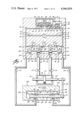
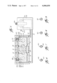
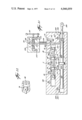
- FIG. 1 is a largely schematic sectional view illustrating a fluidic repeater according to the referred embodiment of the invention
- FIGS. 2 and 3 are fragmentary views similar to FIG. 1 showing modifications
- FIGS. 4 and 5 are views similar to FIGS. 1-3 showing two further modifications
- FIGS. 6, 7, and 8 are elevational, sectional and end views respectively of the end of the amplifier piston of the FIG. 5 embodiment
- FIG. 9 is a view similar to FIG. 8 showing another embodiment
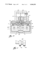
- FIG. 10 is a cross-sectional schematic view of a mechanical to fluidic translator according to the invention.
- FIG. 11 is a sectional view of part of the spool valve shown in FIG. 10;
- FIGS. 12, 13 and 14 are largely schematic sectional views showing further embodiments of the invention.
- FIGS. 15 and 16 are sectional views of feedback elements of the embodiments shown in FIGS. 12 through 14;
- FIG. 17 is a largely schematic cross-sectional view illustrating a fluidic repeater according to an embodiment of the invention.
- FIG. 18 is a view similar to FIG. 17 showing another embodiment
- FIG. 19 is a view similar to FIG. 18 showing an embodiment of the invention using only a single pressure line for control;
- FIGS. 20 and 21 are views similar to FIG. 19 showing other embodiments of the invention using single control lines;
- FIG. 22 is a sectional view of elements of the embodiments shown in FIGS. 20 and 21;
- FIG. 23 is a fragmentary schematic sectional view of a portion of an embodiment of the invention.
- FIG. 24 is a view similar to FIG. 23 showing a portion of another embodiment
- FIG. 25 is a fragmentary, largely schematic sectional view showing a portion of an embodiment of the invention.
- FIG. 26 is a fragmentary sectional view of a commercial embodiment of the invention.
- FIG. 27 is an elevational view of a section of FIG. 26 taken along lines 27--27;
- FIGS. 28 and 29 are sectional views of valves used in the invention's embodiment depicted in FIG. 26;
- FIG. 31 is a sectional view of the transmitter illustrated in FIG. 30 taken along lines 31--31.
- a fluidic repeater comprises a pump or source (not shown) of fluid under pressure connected to conduits marked P and a sump or low pressure fluid reservoir (not shown) connected to conduits marked R.
- a liquid e.g., mineral oil
- a gas e.g., air
- Fluid from pressure source conduit 11 flows through passages 13, 15 in transmitter body 17, through restrictions or orifices 19, 21 to passages 23, 25, and thence out through ports 27, 29.
- the ports empty into the interior of cylinder 31 formed in transmitter body 17.
- Cylinder 31 is vented to reservoir 51 by three ports 33, 35, and 37.
- a four landed spool 39 is moved axially back and forth in cylinder 31 by electromagnetic solenoid 41, which may also be a short stroke torque motor.
- the solenoid is biased to its midposition, as shown, by springs 40 and 42.
- lands 43 and 45 fully or substantially block ports 27 and 29. This reduces the transmitter's idle power requirements. In a modulating system both ports will be partially open in the mid-position of the spool.
- ports 27, 29, and spool 39 with lands 43, 45 Connected to this supply are ports 27, 29, and spool 39 with lands 43, 45. These provide a variable obstructor for opening and closing the ports this variably venting the fluid supplies to provide variable pressure outputs that vary in accordance with the obstructor's position. Since obstructor position is controlled by an electric motor, the system thus far detailed provides an electrofluidic transducer transmitter.
- Lands 77 and 79 are provided with sloping grooves 89 and 91, respectively, whose depth decreases progressing from the ends of the piston toward grooves 73 and 75. Sloping grooves 89 and 91 vent pressure fluid from passages 61 and 63 past lands 77 and 79 to recesses 93 and 95 in the cylinders' sides and hence to the reservoir through passages 85 and 87. Suitable means, not shown, such as a key and slot, are provided to maintain grooves 89 and 91 in azimuthal alignment with recesses 93 and 95. The size of vent openings 97 and 99 connecting grooves 89 and 91 with recesses 93 and 95 increase and decrease when piston 67 is moved axially.
- This venting causes negative feedback to fluid passages 61 and 63.
- Higher pressure at one of passage 61 or 63 than at the other moves free piston 67 in the correct direction to increasingly vent this higher pressure to a reservoir through either groove 89 or 91.
- Relatively lower pressure in passage 61 and 63 than in the other moves free piston 67 in a direction to reduce venting of such lower pressure to the reservoir. Due to this variable negative feedback, piston 67 moves proportionally in response to the degree of movement of spool 39 and then comes to rest.
- Free piston 67 could be connected mechanically to a suitable output such as an indicator, valve or other load. Cylinder 65 and piston 67 would then constitute parts of a receiver connected to the previously described transmitter. Passages 61 and 63 could be replaced by hoses, pipes, or other extended fluid conduits. The system would then constitute a remote indicating or proportional control system.
- piston 67 and cylinder 65 form parts of a fluidic amplifier.
- Piston 67 is relieved at its mid portion by annular groove 101.
- Annular space 103 formed by groove 101 is connected by fluid passage 105 leading to a source of fluid pressure.
- Hoses 113 or 115 is thus connected to a source of pressure fluid through space 103 and passage 105 while the other of conduits is connected to reservoir through either space 81 and passage 85 or space 83 and passage 87.
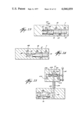
- Hoses 113 and 115 are connected to opposite ends of load cylinder 117, which, together with piston 119 therein, forms a remote receiver.
- Piston rods 121, 123 extend through opposite ends of the cylinder 117, leaving equal areas of piston 119 exposed to pressures in cylinder 117. Piston rod 123 is extended to connect to a mechanical load, e.g., a valve, not shown.
- Piston rod 123 is also connected mechanically by bar 125 to stem 127 of feedback valve 128.
- valve 128 is drawn to a larger scale than load cylinder 117, but it is to be understood that the areas exposed to fluid pressure in the feedback valve are negligibly small compared to those of load cylinder 117.
- Stem 127 extends through sealed opening 129 into cylinder cavity 131 of valve body 163 and connects to cylindrical valve closure 133.
- Closure 133 is provided with two sloping grooves 135 and 137 of increasing depth progressing axially from the ends toward the midportion of the closure. The deepest portions of the grooves being continued axially at constant depth for a certain extent as shown at 139 and 141.
- sloping portions of grooves 135 and 137 are in register axially with annular recesses 143 and 145 in the sides of cylindrical cavity 131.
- Recesses 143 and 145 communicate with ports 147 and 149, respectively, which, in turn, are connected to fluid conduits (hoses) 151 and 153. Conduits 151 and 153 are connected to ports 155 and 157, respectively, leading to the ends of amplifier cylinder 65.
- cylindrical valve body cavity 131 The ends of cylindrical valve body cavity 131 are enlarged at 159 and 161 providing annular spaces communicating both with grooves 135 and 137 and also with passages 163 and 165 leading to conduit 167 connecting with the reservoir.
- closure 133 moves axially, openings 169 and 171 between grooves 135 and 137 and the sides of cylindrical valve body cavity 131 are opened or closed in proportion to the degree of axial movement. This increases the venting to the reservoir of one of the feedback conduits 151, 153 and decreasing the venting of the other.
- FIGS. 2 and 3 there are shown modifications of the FIG. 1 construction.
- FIGS. 2 and 3 show only a portion of the apparatus shown in FIG. 1; the remainder of FIGS. 2 and 3's apparatus being the same as that of FIGS. 1. Parts that are the same as those in FIG. 1 are given like reference numbers and their description will not be repeated.
- An examination of FIGS. 2 and 3 will reveal that whereas in FIG. 1 lands 43 and 45 are disposed so as to substantially block ports 27 and 29 when spool 39 is in midposition; in FIG. 3 lands 43 and 45 are disposed to leave both ports 27 and 29 partly open when spool 39 is in midposition.
- FIGS. 2 and 3 differ from the FIG. 1 construction in two additional respects.
- guide lands 53 and 55 are omitted from spool 39, as are leakage return ports 33 and 37 and atmosphere vent passages 57 and 59. These of course can be used wherever it is found necessary or desirable.
- feedback valve 128 is omitted. Instead feedback valve means comprising grooves 135 and 137 controlling fluid conduits 151 and, respectively, 153 are provided directly on the ends of valve stems 121 and 123.
- FIG. 4 there is shown another modification of the FIG. 1 system. Again like parts are given like reference numbers and will not again be described.
- FIGS. 1 and 4 The primary difference between the embodiments of the invention shown in FIGS. 1 and 4 is that in FIG. 4 the spool controlled ports 27 and 29 of FIG. 1 are replaced by nozzles 27A and 29A whose flow is controlled by obstructor 39A.
- the latter is a hand operated wheel, as distinguished from the electric motor actuated spool 39 of FIG. 1.
- Bearing 201 at one side of cylindrical obstructor 39A is internally threaded to receive threaded pin 203 on which the obstructor pivots. As the obstructor is rotated it moves axially approaching one or the other of nozzles 27A or 29A and moving farther away from the nozzle not approached. By this means the fluid pressure in conduits 23 and 25 is varied.
- Obstructor 39A is provided with unthreaded pivot pin 205 received in bearing 206 in obstructor support body 209.
- Nozzles 27A and 27B discharge into the interior of body 209.
- Radial passages 211 and 213 in pins 203 and 205 respectively communicate with the interior of body 209 and connect with axial fluid passage 207 which discharges into return line 35 leading to the fluid reservoir.
- FIGS. 1 and 4 Another difference between the construction of FIGS. 1 and 4 lies in the construction of the feedback valve 128A that is mechanically linked to load piston rod 123.
- Feedback valve 128A variably vents fluid passages 61 and 63 via grooves 135 and 137, which, in this case, are connected together to form one long groove. Venting through grooves 135 and 137 can also be outwardly into the spaces 220 inside annular sealing boots 221 and thence through groove 222 back to the reservoir.
- feedback valve 128A has moved far enough to equalize the pressure in fluid passages 61 and 63, piston 101 moves back to neutral position. Load piston 119 remains in its new position as controlled by the setting of manual obstructor 39A.
- FIG. 4 Another difference between the embodiments of FIGS. 1 and 4 lies in the fact that in the FIG. 4 construction the amplifier piston 101 is not provided with feedback grooves in its ends like the grooves 89 and 91 of the FIG. 1 embodiment.
- FIG. 5 there is shown a further embodiment similar to the embodiments of FIGS. 1-4 wherein like reference numbers refer to like parts that will not be redescribed.
- the FIG. 5 embodiment includes a manually activated hand wheel type obstructor 39A cooperating with nozzles 27A and 29A, rather than an electric motor activated spool 39 cooperating with ports 27 and 29 as in FIGS. 1-3.
- the amplifier piston is provided with feedback means.
- the FIG. 5 construction instead of providing the ends of amplifier piston 101 with sloping grooves as at 89, 91 extending all the way to the outer ends of the piston as in FIG. 1-3, the sloping grooves 89A and 91A of the FIG.
- FIG. 9 shows feedback groove 91E of rectangular cross section as an alternative to the V-shape cross section of groove 91A of FIG. 8.
- FIG. 5 No load cylinder and piston are shown in the FIG. 5 construction, but it is to be understood that amplifier output passages 113 and 115 connect via passages 117A and 117B leading to a suitable load cylinder which usually will be provided with further feedback means as in FIGS. 1-4. Without a load feedback the load piston will ultimately move to the limit of its travel regardless of the magnitude of the input at obstructor 39. The rate of this movement of the load piston will vary in proportion to the magnitude of the input at obstructor 39A. In some applications the load feedback means of the FIGS. 1-4 embodiments could also be omitted.
- FIG. 5 illustrates the use of a filter screen 225 between conduit 11 leading to the source of pressure fluid and the orifices 19 and 21. This is desirable to prevent blockage of the orifices by foreign matter.
- This constructional detail though not shown in FIGS. 1-4, is to be understood as being applicable to all embodiments of the invention.
- FIG. 10 shows an embodiment of the invention that is much the same as that of FIG. 5. Differences include modification of the feedback groove system in the amplifier piston and the use of an electric "flapper" in place of hand wheel obstructor 39A. Like parts are given like reference numbers and their description will not be repeated.
- the amplifier piston feedback groove system in FIG. 10 is similar to the system illustrated by FIG. 5 except short sloping grooves 89A and 91A are omitted.
- An initial axial motion of the piston 101 sufficient to communicate annular groove 89B or 91B with vent passage 85 or 87 is required before any feedback will occur. Thereafter, further movement of the piston 101 in the same direction will cause increasing venting.
- lands 77 and 79 can be inwardly flaring or tapered, e.g., conically or in other manner annularly relieved between annular grooves 73 and 89B along one end and between annular grooves 75 and 91B at the other end, as shown in FIG. 11. This will effect a result similar to that attained by the embodiment illustrated in FIG. 5.
- the outermost parts of the lands will be cylindrical, for guide purposes, as shown at 79B.
- Electric flapper 41A shown in FIG. 10 driving flapper type obstructor 39B includes horseshoe magnets 231 and 233 disposed opposite pole to opposite pole with flapper 39B pivoted therebetween at 235.
- Tension springs 237 and 239 are connected to one end of the flapper and to motor housing 241 and adjustment screw 243 which normally centers the other end of the flapper between nozzles 27A and 29A.
- the flapper When an electric signal is applied to either input 111A or 111B of solenoid 41A or 41B the flapper is magnetized a proportional amount. This moves it toward or away from nozzle 27A or 29A. This variably vents passages 23 and 25. Fluid leaving nozzles 27A and 29A returns to the fluid reservoir through passages 35A and 35B.
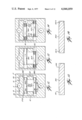
- FIGS. 12-14 show rudimentary fluidic repeater apparatus according to an embodiment of the invention in which transmitter obstructor 39C or 39D is of the needle valve type rather than the spool valve type shown in FIGS. 1-3 or the jet interference types shown in FIGS. 4, 5, and 10.
- obstructor 39C is a cylindrical plug axially movable relative to cylindrical ports 27B and 29B.
- Plug 39C is provided with sloping grooves 251 and 253 similar to grooves 89 and 91 of the amplifier piston of FIG. 1. According to the axial position of plug 39C more or less fluid is vented from fluid source passages 23 and 25 to chamber 255 and then through passage 35 to reservoir return conduit 51.
- No means for moving plug 39C is shown, but it is to be understood that any suitable means can be used, e.g., any of the manual or motor means used in the previously described embodiments.
- the transmitter obstructor shown in FIG. 13 is the same as that in FIG. 12.
- the transmitter obstructor shown in FIG. 14 is the same as in FIGS. 12 and 13 except that the ends of the obstructor plug 39D are provided with spiral helical grooves 251A, 253A spiraling inward and progressing axially towards the plug ends, rather than the sloping grooves 251, 253 of the embodiments of FIGS. 12 and 13.
- the two groove constructions are further illustrated in FIGS. 15 and 16.
- receiver piston 101C is provided with sloping feedback grooves 89 and 91 similar to those shown in the embodiments of FIGS. 1-3 whereby axial motion of piston 101C due to difference in pressure between fluid passages 61 and 63 causes such venting through chamber 255 and passage 35 to reservoir return conduit 51 as to eliminate the pressure differential.
- the receiver piston constructions of FIGS. 13 and 14 are the same as that of FIG. 12 except that instead of sloping grooves 89 and 91 of configuration like transmitter grooves 251 and 253, the receiver pistons of FIGS. 13 and 14 are provided with spiral helical grooves of configuration similar to the grooves 251A and 253A.
- the various vent groove configurations described herein as applicable to the transmitter plug (FIGS. 15 and 16), the amplifier or receiver piston (FIGS. 1-3, 5-14) and the load feedback piston (FIGS. 1-4) may be interchanged between the various embodiments described hereinabove or hereinafter, as may be described or required for any reason, for example to correlate the transmitter obstructor position-vent function, the amplifier piston position-vent function, and the load feedback valve position-vent function.
- a transmitter obstructor moves relative to a pair of openings.
- These may be side ports in a spool valve as in FIG. 1, jet nozzles as in FIGS. 4 and 10, or needle valve ports as in FIGS. 12-14.
- the pair of openings open to some form of chamber means, e.g., a cylinder (FIG. 1), cylindrical spaces in a hand wheel block (FIG. 4), a chamber in the transmitter block (FIG. 10), or a cylindrical chamber (FIGS. 12-14).
- flow from the pair of openings is controlled by some form of barrier means, e.g., piston lands (FIG.
- the obstructor and openings provide means to variably vent a pair of pressure fluid passages downstream from flow restrictors.
- Responder means e.g., amplifier and/or load cylinders, are connected to the fluid passages.
- Feedback means from the amplifier and/or load cylinder variably vent the pair of fluid passages opposite to the variation by the obstructor.
- the feedback means comprises variable cross section surface passages in the amplifier or load or receiver piston or several of these or in the walls of the cylinders surrounding these pistons.
- the responder means of the invention can be actuated by other forms of transmitter than those described above in which the transmitter variably vents a pair of fluid passages downstream from flow restrictors therein, the fluid passages upstream from the restrictors leading to a source of constant fluid pressure, and the pressures downstream from the restrictors being conducted by two fluid lines to the responder.
- variable venting variable pressures can be generated by making the restrictors variable and conducting the downstream pressures by two lines to the responder.
- the transmitter may be modified to affect change in only one pressure. A single line may then be used between transmitter and responder.
- FIG. 17 there is shown an embodiment to the invention, the same as that of FIG. 2 insofar as the amplifier and receiver are concerned, but employing a modified form of transmitter.
- motor 41 acts to move spool 39 axially in cylinder 31 to vary the position of lands 43 and 45 relative to ports 27 and 29, as in FIG. 3.
- conduit 11A connected to cylinder 31 leads to a pressure source rather than to a reservoir.
- the pressure in lines 61 and 63 leading to amplifier piston 101 are varied in accordance with the degree of throttling, or obstruction, produced by spool 39.
- This is an example of control by variable obstruction of a pressure source.
- FIG. 17 The operation of the embodiment illustrated in FIG. 17 is the same as that of the embodiment illustrated by FIG. 1, in that electric signals inputted through electric motor 41 move spool 39 to vary the pressure in lines 61 and 63. This differential pressure in turn moves amplifier piston 101, causing ports 109 and 110 to be opened to the reservoir and pump pressure, respectively. The differential pressure thus applied to load piston 119 causes it to move axially, moving connected clevis 124 to actuate a load (not shown). Negative feedback, in accordance with the preferred embodiment of the invention, is effected by grooves 89 and 91 in the amplifier and by grooves 135 and 137 in the load piston.
- the feedback provided by these grooves limits the travel of both the amplifier and load pistons so the load pistons movement varies in an amount directly related to the amount of electrical imput to motor 41.
- the precise relationship, linear or otherwise, between the signal strength and loan movement depends on the size and shape of the feedback grooces.
- piston 119 comes to rest at a balance of forces, not pressures. If, however, the reservoir pressure is atmospheric pressure, then the pressure on clevis 124 will effect a precise compensation and piston 119 will come to rest with a balance of pressures in lines 113 and 115, (assuming the load on clevis 124 exerts no force when the clevis is a rest).
- FIG. 18 there is shown a construction similar to that of FIG. 17 except no amplifier is employed. Like parts bear like reference numbers. It will be seen that variable pressures downstream of throttling spool 39 at port 27 and 29 are applied directly to loan piston 119 through lines 113 and 115. Negative feedback in accordance with the invention is effected by grooves 135 and 137 in the load piston. These grooves are always in position to vent some of the pressure fluid back to the reservoir so there will be no buildup of hydraulic fluid in lines 113 and 115 sufficient to lock the system.
- FIG. 19 there is shown another embodiment of the invention adopted for a single line connecting between the transmitter and receiver.
- the construction is similar to that of FIG. 18 in that no amplifier is used and similar to that of FIG. 2 in that the transmitter functions by variably venting the working fluid rather than by variably throttling it to effect pressure change.
- Reference numbers for parts similar to those of FIG. 2 will be employed, increased by 200.
- the transmitter of FIG. 19 employs a manual input in the form of lever 241, which moves spool 239 axially.
- single line 224 is variably vented to return-to-reservoir conduit 251. Venting varies in accordance with the position of land 245 relative to ports 228 and 229.
- Load piston 319 is connected on one side by fluid passage 263 and flow restrictor 221 to conduit 211, which leads to the source of pressure fluid.
- Fluid passage 224 is connected to passage 263 by branch line or passage 226. The flow of fluid in this branch passage is used to vary the pressure of the fluid in passage 263 applied to one side of load piston 319. Pressure on the opposite side of piston 319 is maintained constant, e.g., by connection through passage 285 leading to a conduit connected to a reservoir.
- the area at the end of piston rod 321 is connected by passage 366 to conduit 368. This conduit leads to a source of fluid pressure that may or may not be the same pressure source as is connected to conduit 211.
- Piston rod 323 is connected to clevis 324 for actuating a load (not shown).
- the aperture through which the clevis extends out of the receiver housing is sealed by O-ring 326. This prevents leakage from chamber 328 at the end of piston rod 323.
- the chamber is connected by passage 366 to conduit 367. This conduit leads to a reservoir.
- negative feedback is achieved by the use of groove 337 in piston rod 323 that variably connects chamber 328 to fluid passage 353.
- Fluid passage 353 is connected to line 224 and passage 226.
- actuator 241 When actuator 241 is moved to allow venting to increase in line 224, fluid pressure drops in passage 226 causing piston 319 to move to the right as illustrated in the drawing. Such movement causes groove 337 to also move to the right whereby only its shallow left end portion connects passage 353 to chamber 328. Venting, by passage 353, is thereby reduced, raising the pressure in passage 226 and bringing piston 319 to rest.
- FIG. 20 there is shown an embodiment to the invention that is the same as that of FIG. 19, except the transmitter functions by variable throttling as in FIG. 18 instead of by variable venting as in FIG. 19.
- Like parts are given like numbers to the constructions shown in FIGS. 18 and 19, whereby the operation will be obvious and repeated description rendered unnecessary.
- variable restrictor means 245 moves to variably throttle pressure fluid flowing from conduit 11A to line 224 and passage 226 to the right of piston 319. This causes piston 319 to move to the right or left according to whether pressure falls or rises. Negative feedback by groove 337 causes the initial pressure change in passage 226 to be eliminated, bringing the load piston to rest in a new position.
- FIG. 21 there is shown an embodiment of the invention similar to that shown in FIG. 19.
- a single line is employed between transmitter and receiver and the transmitter functions by variable venting to create the desired pressure change.
- an amplifier is employed in this embodiment of the invention as was illustrated in FIGS. 2 and 17. As in FIG. 4, the amplifier, in this construction, is not provided with feedback means. Like parts are given like reference numbers.
- the feedback groove tapers in different directions according to the requirements of the particular embodiment of the invention so as to always yield negative feedback in the system. If groove 137 in FIG. 21 tapered in a direction opposite to that shown in the illustration, positive feedback would be created that would accelerate the movement of the load piston toward its limiting position in one direction or the other; instead of producing a load piston position that is a direct known function of the movement of the manual actuator.
- a pin 401 is provided at the end of cylinder 65 in which the amplifier spool moves and limits the spool's travel.
- FIG. 22 there is shown a variation of the amplifier piston illustrated by FIG. 21, constructed to incorporate a negative feedback groove 91.
- Negative feedback on the amplifier may be used in addition to or in place of negative feedback on the load piston.
- negative feedback is employed with the load piston whether or not it is included in the amplifier. This prevents the load piston from tending to move toward the limit of its range of possible movement as soon as the transmitter activator is moved marginally.
- FIG. 23 there is shown a further variation of the amplifier shown in FIG. 21.
- amplifier spool 101 is exposed to pressure by conduit 403 from a constant pressure source that is at a lower pressure than the pressure in conduit 211. This pressure opposes the variable pressure received by passage 203, which is responsive to the transmitter and causes the amplifier piston to move.
- left end of amplifier spool 101 is exposed to reservoir pressure received through passage 404.
- a helical compression spring 405 is added to provide some of the reaction force on the amplifier spool needed to bring the spool into balance with transmitter pressure.
- This spring eliminates the need for an additional constant pressure source by providing a bias on piston 101. It also changes the system's response characteristics, since the reactive force provided by the spring varies with its degree of compression according to Hooke's Law.
- the spring is disposed concentrically around a pin 407, which centers the spring and functions like pin 401 (FIG. 21) to keep land 77 at the end of spool 101 from blocking passage 409 to conduit 409. If desired, the variation of the preferred embodiment of the invention illustrated by FIG. 23 can be used in conjunction with those novel features disclosed in FIG. 22.
- end 411 of amplifier spool 101 has a reduced end area so forces on the ends of the spool can be balanced by pressure acting on the left end of the piston from conduit 406.
- Conduit 406 is at the same pressure as conduits 211 and 11. This modification eliminates the need for spring 405 and provides a system having a different response characteristic because the pressure on spool end 411 remains constant.
- This construction can be used in combination with the feedback constructions illustrated in the embodiment of the invention shown in FIG. 22.
- FIG. 21 can be modified for use with a variable restrictor or throttling type of transmitter.
- a variable restrictor or throttling type of transmitter Such a variation is illustrated by FIG. 25.
- the operation of this type of transmitter is the same, operationally, as the embodiment shown in FIG. 20. It may be noted, however, that to prevent the possibility of hydraulic locking due to leakage around control land 245 and guide land 246 the ends of the transmitter cylinder are vented to reservoir pressure by conduits 513 and 515.
- a similar construction is used in the embodiment of the invention illustrated in FIG. 21.
- This variation of the preferred embodiment of the invention's transmitter illustrated by FIG. 25 can be used with any of the amplifier constructions illustrated by FIGS. 21 through 24.
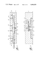
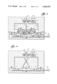
- FIG. 26 illustrates a commercial embodiment of the invention.
- transmitter 600 has a lever 602 connected to grooved valve rod 604 and adapted to move the valve rod to variably obstruct the flow of fluid from pressure conduit 606 through grooves 608 and 610, thus creating a pressure differential between lines 612 and 614.
- Differential pressure moves spool valve 618 in amplifier 620.
- Spool valve 618 is supplied with feedback grooves 622 and 624. Movement of the amplifier's spool valve creates a pressure imbalance between conduits 626 and 628. This imbalance of forces moves piston 632 in load cylinder 632 as has been described earlier. Piston 632 is connected to clevis 634 by rod 636.
- the clevis is attached to a plate 638, which is provided with a cam 640 used to actuate load feedback means 642.
- Load feedback means 642 has a body 643 in which is mounted a groove valve 644.
- the valve is attached to a wheel 646 and constrained by spring 648 to move to a position dependent on the position of inclined form 640 and thus on the position of piston 630 and clevis 634.
- lines 612 and 614 are variably vented by grooves 650 and 652 in valve rod 644 to return line 654. This venting tends to reduce the pressure imbalance acting on the amplifier's spool valve causing it to return to a neutral position and stopping movement of the load piston.
- the clevis and the load attached to it will come to rest at a position dependent on the displaced position of the transmitter's control lever 602.
- amplifier spool valve and feedback means both incorporate feedback means taught by the preferred embodiment of the invention. These feedback means are shown working in cooperation to produce a final clevis position that is a known function of the control lever's position. Also, since the load pistion has unequal areas exposed to the differential pressures from conduits 626 and 628, the load piston will come to rest at a balance of forces on its two sides rather than at a balance of pressures in lines 626 and 628.
- FIG. 27 shows an isometric view of load feedback means 642 along lines 27--27 of FIG. 26.
- Springs 648 are shown biasing roller 646, which is attached to valve rod 644, into contact with inclined form 640.
- the cam which is shown as being “T” shaped in this illustration, rests on lower roller 656, which is a guide roller.
- FIGS. 28 and 29 illustrate sectional views of the feedback valve rod and amplifier spool valve, respectively, clearly showing the feedback grooves taught by the preferred embodiment of the invention.
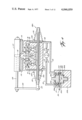
- FIG. 30 illustrates a second commercial embodiment of the invention.
- a rotary transmitter 700 and a rotary load feedback means 702 operate with an amplifier-feedback 704, which is substantially the same as amplifier 620 illustrated and described in FIG. 26, and hydraulic motor 706 to produce a rotary fluidic servo system.
- Motor 706 may be, for example, a Hydreco model 2M000B2A1 hydraulic motor suitably modified to operate with a double ended output shaft (see accompanying description thereof).
- Transmitter 700 has a rotor 701 rotatable about a head 702.
- the rotor is pivotally mounted on pin 704 and shaft 707.
- the head has two arms 706 and 706' extending radially into contact with the inner perphery of the rotor.
- the rotor is constrained by stop 703 engaging arm 706 or arm 706' to be rotatable by wheel 705 through slightly less than 180 degrees.
- the inner periphery of rotor 701 is provided with an eccentric circular groove 712.
- Bottom plate 709 is affixed to head 701 with screws 711. Seal rings 713 seal off space 710 between the rotor 701 and head 702 of the transmitter.
- Fluid under pressure is introduced from a source, not shown, to conduit 708.
- This eccentric groove which is clearly illustrated in FIG. 31, differentially pressurizes conduits 714 and 716 that extend to the ends of arms 706 and 706' and are connected to the control inputs of fluidic amplifier 704.
- the bottom of groove 712 is circular when viewed in plan, as in FIG. 31, the circle being slightly eccentric to the axis about which the rotor rotates, i.e. the axis of pin 704 and shaft 707.
- the center of this circle is slightly displaced from the rotor's axis along the line joining the rotor axis and the middle of stop 703 in a direction away from pin 703.
- Adjacent pin 703 the groove is of minimum radial depth; diametrically opposite from pin 703 the groove is of maximum depth.
- the width of the groove is uniform and of less extent than the height of the arms 706 and 706' so that fluid leaving fluid passages 714 and 716 (see FIG. 31) must travel a short distance along the groove before it can enter space 710, and in the process the fluid flow is throttled according to the groove's depth.
- conduits 714 and 716 are differentially pressurized by fluid flowing under pressure through their respective sections of groove 712
- amplifier 704 acts to control hydraulic motor 706 by establishing differential pressures in output conduits 720 and 722.
- Motor 706 has a two ended output shaft.
- End 724 is connected to a load or indicator as may be appropriate.
- End 726 is connected through coupling 728 to the rotary head 730 of load feedback means 702.
- Feedback 702 is structurally identical to transmitter 700.
- differentially pressurized conduits 714 and 718 are variably vented via eccentric groove 732 through communicating chamber 734 to conduit 713, which is connected to a fluid reservoir, not shown.
- Variable venting tends to equalize pressures in conduits 714 and 716, causing the rotation of shaft 724 of hydraulic motor 706' to cease at a position that is a known function of the rotational displacement of transmitter 700's control knob 705.
- Stop 703 is adapted to prevent the rotation of eccentric groove 712 in head 701 past its point of greatest difference in flow with respect to the conduits opening into said eccentric groove from control head 707.
- Stop 736 performs the same function with respect to venting these conduits in responder 702.
- FIG. 31 is a sectional view of transmitter 700 taken along line 31--31. It illustrates the fluid communication of conduits 714 and 716 with eccentric groove 712 and shows the differential variable obstruction provided by the groove between conduit 708 and each of conduits 714 and 716.
- the geometry of this eccentric groove may be varied in both the transmitter and the responder to obtain a desired feedback function between the transmitter and the load in the illustrated servo system.
Landscapes
- Engineering & Computer Science (AREA)
- Physics & Mathematics (AREA)
- Fluid Mechanics (AREA)
- Mechanical Engineering (AREA)
- General Engineering & Computer Science (AREA)
- Servomotors (AREA)
- Reciprocating Pumps (AREA)
- Supply Devices, Intensifiers, Converters, And Telemotors (AREA)
- Fluid-Pressure Circuits (AREA)
Priority Applications (11)
| Application Number | Priority Date | Filing Date | Title |
|---|---|---|---|
| US05/521,036 US4046059A (en) | 1974-07-18 | 1974-11-05 | Fluidic repeater |
| CA231,209A CA1045980A (en) | 1974-07-18 | 1975-07-10 | Fluidic repeater |
| GB2998475A GB1515173A (en) | 1974-07-18 | 1975-07-17 | Fluidic repeater |
| FR7522445A FR2278965A1 (fr) | 1974-07-18 | 1975-07-17 | Repeteur fluidique |
| DE19752532028 DE2532028A1 (de) | 1974-07-18 | 1975-07-17 | Fluidverstaerker |
| JP50088779A JPS6052321B2 (ja) | 1974-07-18 | 1975-07-18 | 流体作動式中継器 |
| US05/622,760 US4094229A (en) | 1974-11-05 | 1975-10-15 | Fluidic repeater |
| US05/720,420 US4152971A (en) | 1974-11-05 | 1976-09-03 | Fluidic repeater |
| US05/962,858 US4335645A (en) | 1974-07-18 | 1978-11-22 | Fluidic repeater |
| US06/027,668 US4404897A (en) | 1974-07-18 | 1979-04-06 | Fluidic repeater |
| US06/566,755 US4637474A (en) | 1974-11-05 | 1983-12-29 | Tractor and towed implement with elevation control system for implement including pressure responsive valve actuator |
Applications Claiming Priority (2)
| Application Number | Priority Date | Filing Date | Title |
|---|---|---|---|
| US05/489,829 US3988966A (en) | 1974-07-18 | 1974-07-18 | Fluidic repeater |
| US05/521,036 US4046059A (en) | 1974-07-18 | 1974-11-05 | Fluidic repeater |
Related Parent Applications (1)
| Application Number | Title | Priority Date | Filing Date |
|---|---|---|---|
| US05/489,829 Continuation-In-Part US3988966A (en) | 1974-07-18 | 1974-07-18 | Fluidic repeater |
Related Child Applications (3)
| Application Number | Title | Priority Date | Filing Date |
|---|---|---|---|
| US05/622,760 Continuation-In-Part US4094229A (en) | 1974-07-18 | 1975-10-15 | Fluidic repeater |
| US05/720,420 Division US4152971A (en) | 1974-11-05 | 1976-09-03 | Fluidic repeater |
| US06/062,964 Continuation-In-Part US4283990A (en) | 1978-01-27 | 1979-08-02 | Fluidic repeater |
Publications (1)
| Publication Number | Publication Date |
|---|---|
| US4046059A true US4046059A (en) | 1977-09-06 |
Family
ID=27049841
Family Applications (2)
| Application Number | Title | Priority Date | Filing Date |
|---|---|---|---|
| US05/521,036 Expired - Lifetime US4046059A (en) | 1974-07-18 | 1974-11-05 | Fluidic repeater |
| US06/027,668 Expired - Lifetime US4404897A (en) | 1974-07-18 | 1979-04-06 | Fluidic repeater |
Family Applications After (1)
| Application Number | Title | Priority Date | Filing Date |
|---|---|---|---|
| US06/027,668 Expired - Lifetime US4404897A (en) | 1974-07-18 | 1979-04-06 | Fluidic repeater |
Country Status (6)
| Country | Link |
|---|---|
| US (2) | US4046059A (enExample) |
| JP (1) | JPS6052321B2 (enExample) |
| CA (1) | CA1045980A (enExample) |
| DE (1) | DE2532028A1 (enExample) |
| FR (1) | FR2278965A1 (enExample) |
| GB (1) | GB1515173A (enExample) |
Cited By (6)
| Publication number | Priority date | Publication date | Assignee | Title |
|---|---|---|---|---|
| US4215844A (en) * | 1978-08-28 | 1980-08-05 | The Babcock & Wilcox Company | Valve actuator system |
| DE3024171A1 (de) * | 1980-06-27 | 1982-01-21 | Danfoss A/S, 6430 Nordborg | Hydrostatische stelleinrichtung, insbesondere lenkeinrichtung fuer fahrzeuge |
| US4355506A (en) * | 1977-08-26 | 1982-10-26 | Leonard Willie B | Pump-motor power limiter and pressure relief |
| USRE32588E (en) * | 1978-08-28 | 1988-02-02 | The Babcock & Wilcox Company | Valve actuator system |
| US20140251447A1 (en) * | 2011-10-12 | 2014-09-11 | Zodiac Hydraulics | Servovalve having two stages and a pilot stage adapted to such a servovalve |
| CN113915188A (zh) * | 2021-10-18 | 2022-01-11 | 山东泰丰智能控制股份有限公司 | 一种自适应液压控制系统 |
Families Citing this family (11)
| Publication number | Priority date | Publication date | Assignee | Title |
|---|---|---|---|---|
| US4335645A (en) | 1974-07-18 | 1982-06-22 | Leonard Willie B | Fluidic repeater |
| US4132152A (en) * | 1976-10-29 | 1979-01-02 | Hunkar Laboratories, Inc. | Closed loop electro-fluidic control system |
| JPS53157289U (enExample) * | 1977-05-16 | 1978-12-09 | ||
| DE2949657C2 (de) * | 1979-12-11 | 1982-09-09 | Danfoss A/S, 6430 Nordborg | Ventilanordnung für einen hydraulischen Servomotor |
| JPS5737103A (en) * | 1980-08-08 | 1982-03-01 | Leonard Willie Burt | Fluid pressure repeater |
| DE3106086A1 (de) * | 1981-02-19 | 1982-09-09 | Mannesmann Rexroth GmbH, 8770 Lohr | "vorrichtung zum regeln eines stellgliedes, insbesondere zum regeln des hubwerkes eines schleppers, maehdreschers o.dgl." |
| US4574687A (en) * | 1982-07-20 | 1986-03-11 | Mannesmann Rexroth Gmbh | Apparatus for positioning an adjusting member |
| US4569372A (en) * | 1984-08-28 | 1986-02-11 | Commercial Shearing, Inc. | Remote valve operators |
| JPS62184113U (enExample) * | 1986-05-16 | 1987-11-21 | ||
| CA2173380C (en) * | 1996-04-03 | 2001-07-10 | Michael G. Mancell | Power steering fluid reservoir |
| US20020179029A1 (en) * | 1998-09-09 | 2002-12-05 | Watson John P. | Hydraulically actuated, electrically controlled linear motor |
Citations (11)
| Publication number | Priority date | Publication date | Assignee | Title |
|---|---|---|---|---|
| US2709421A (en) * | 1952-07-29 | 1955-05-31 | Gen Electric | Hydraulic amplifier |
| US2841168A (en) * | 1952-11-19 | 1958-07-01 | Kleelavite Company Ltd | Hydraulic control valve apparatus |
| US2973746A (en) * | 1957-06-03 | 1961-03-07 | Edward C Jupa | Hydraulic servo valve |
| US2989950A (en) * | 1958-06-04 | 1961-06-27 | Lockman Nathan | Pneumatic control device |
| US3040715A (en) * | 1958-12-24 | 1962-06-26 | Bendix Corp | Two-stage pneumatic servo control |
| US3215044A (en) * | 1962-07-24 | 1965-11-02 | Lissau Frederic | Hydraulic positioning servo system |
| US3415163A (en) * | 1966-02-09 | 1968-12-10 | Fujitsu Ltd | Hydraulic torque amplifier system with variable preamplifier duct orifice cross section |
| US3426258A (en) * | 1965-01-18 | 1969-02-04 | Richard W Van Pelt | Control mechanism actuating motor in incremental manner |
| US3486416A (en) * | 1968-02-08 | 1969-12-30 | Bendix Corp | Fluid remote position indicator |
| US3583285A (en) * | 1969-07-17 | 1971-06-08 | Deere & Co | Pressure responsive direction control valve |
| US3665806A (en) * | 1968-09-30 | 1972-05-30 | Lucas Industries Ltd | Fluid operated servomechanism |
Family Cites Families (4)
| Publication number | Priority date | Publication date | Assignee | Title |
|---|---|---|---|---|
| US2619794A (en) * | 1945-03-12 | 1952-12-02 | Rolls Royce | Control means for variable jet nozzles of jet propulsion units |
| US3017868A (en) * | 1960-03-01 | 1962-01-23 | Raymond M Ginder | Oil motor |
| US3211182A (en) * | 1962-12-05 | 1965-10-12 | Jarry Hydraulics Ltd | Servo valve with rotary first stage |
| US3187509A (en) * | 1964-09-16 | 1965-06-08 | Sundstrand Corp | Hydrostatic transmission |
-
1974
- 1974-11-05 US US05/521,036 patent/US4046059A/en not_active Expired - Lifetime
-
1975
- 1975-07-10 CA CA231,209A patent/CA1045980A/en not_active Expired
- 1975-07-17 GB GB2998475A patent/GB1515173A/en not_active Expired
- 1975-07-17 DE DE19752532028 patent/DE2532028A1/de not_active Withdrawn
- 1975-07-17 FR FR7522445A patent/FR2278965A1/fr active Granted
- 1975-07-18 JP JP50088779A patent/JPS6052321B2/ja not_active Expired
-
1979
- 1979-04-06 US US06/027,668 patent/US4404897A/en not_active Expired - Lifetime
Patent Citations (11)
| Publication number | Priority date | Publication date | Assignee | Title |
|---|---|---|---|---|
| US2709421A (en) * | 1952-07-29 | 1955-05-31 | Gen Electric | Hydraulic amplifier |
| US2841168A (en) * | 1952-11-19 | 1958-07-01 | Kleelavite Company Ltd | Hydraulic control valve apparatus |
| US2973746A (en) * | 1957-06-03 | 1961-03-07 | Edward C Jupa | Hydraulic servo valve |
| US2989950A (en) * | 1958-06-04 | 1961-06-27 | Lockman Nathan | Pneumatic control device |
| US3040715A (en) * | 1958-12-24 | 1962-06-26 | Bendix Corp | Two-stage pneumatic servo control |
| US3215044A (en) * | 1962-07-24 | 1965-11-02 | Lissau Frederic | Hydraulic positioning servo system |
| US3426258A (en) * | 1965-01-18 | 1969-02-04 | Richard W Van Pelt | Control mechanism actuating motor in incremental manner |
| US3415163A (en) * | 1966-02-09 | 1968-12-10 | Fujitsu Ltd | Hydraulic torque amplifier system with variable preamplifier duct orifice cross section |
| US3486416A (en) * | 1968-02-08 | 1969-12-30 | Bendix Corp | Fluid remote position indicator |
| US3665806A (en) * | 1968-09-30 | 1972-05-30 | Lucas Industries Ltd | Fluid operated servomechanism |
| US3583285A (en) * | 1969-07-17 | 1971-06-08 | Deere & Co | Pressure responsive direction control valve |
Cited By (8)
| Publication number | Priority date | Publication date | Assignee | Title |
|---|---|---|---|---|
| US4355506A (en) * | 1977-08-26 | 1982-10-26 | Leonard Willie B | Pump-motor power limiter and pressure relief |
| US4215844A (en) * | 1978-08-28 | 1980-08-05 | The Babcock & Wilcox Company | Valve actuator system |
| USRE32588E (en) * | 1978-08-28 | 1988-02-02 | The Babcock & Wilcox Company | Valve actuator system |
| DE3024171A1 (de) * | 1980-06-27 | 1982-01-21 | Danfoss A/S, 6430 Nordborg | Hydrostatische stelleinrichtung, insbesondere lenkeinrichtung fuer fahrzeuge |
| US20140251447A1 (en) * | 2011-10-12 | 2014-09-11 | Zodiac Hydraulics | Servovalve having two stages and a pilot stage adapted to such a servovalve |
| US9644645B2 (en) * | 2011-10-12 | 2017-05-09 | Zodiac Hydraulics | Servovalve having two stages and a pilot stage adapted to such a servovalve |
| CN113915188A (zh) * | 2021-10-18 | 2022-01-11 | 山东泰丰智能控制股份有限公司 | 一种自适应液压控制系统 |
| CN113915188B (zh) * | 2021-10-18 | 2024-05-07 | 山东泰丰智能控制股份有限公司 | 一种自适应液压控制系统 |
Also Published As
| Publication number | Publication date |
|---|---|
| JPS5134391A (enExample) | 1976-03-24 |
| DE2532028A1 (de) | 1976-02-05 |
| US4404897A (en) | 1983-09-20 |
| GB1515173A (en) | 1978-06-21 |
| FR2278965A1 (fr) | 1976-02-13 |
| FR2278965B1 (enExample) | 1984-04-06 |
| CA1045980A (en) | 1979-01-09 |
| JPS6052321B2 (ja) | 1985-11-19 |
Similar Documents
| Publication | Publication Date | Title |
|---|---|---|
| US4046059A (en) | Fluidic repeater | |
| US4152971A (en) | Fluidic repeater | |
| EP0283053B1 (en) | Hydraulic valve arrangement | |
| US6073652A (en) | Pilot solenoid control valve with integral pressure sensing transducer | |
| US3988966A (en) | Fluidic repeater | |
| US5735122A (en) | Actuator with failfixed zero drift | |
| US3331383A (en) | Electro-hydraulic servo valves | |
| US4321941A (en) | Pilot operated pressure relief valve | |
| US4602481A (en) | Fluid actuator for binary selection of output force | |
| US3771564A (en) | Pilot control valve | |
| CA1088373A (en) | Control for a variable displacement pump or motor | |
| US4335645A (en) | Fluidic repeater | |
| US3028880A (en) | Fluid flow control valve | |
| US5156189A (en) | High flow control valve | |
| US3653409A (en) | Power assist servo control for a valve | |
| US4254689A (en) | Fluidic repeater | |
| US4212323A (en) | Power assist proportional remote controller | |
| CA1037819A (en) | Differential pressure sensing valve | |
| US4227440A (en) | Fluidic repeater | |
| EP0084213A2 (en) | Pilot control valve for load sensing hydraulic system | |
| US3587617A (en) | Fluid control apparatus | |
| US3444877A (en) | Hydraulic fluid amplifier controlled servovalve | |
| US2904055A (en) | Hydraulic amplifier valve with feedback | |
| US3862645A (en) | Pilot control valve | |
| US4510848A (en) | Shear-type fail-fixed servovalve |