US4046033A - Control apparatus for automatic transmission - Google Patents
Control apparatus for automatic transmission Download PDFInfo
- Publication number
- US4046033A US4046033A US05/614,700 US61470075A US4046033A US 4046033 A US4046033 A US 4046033A US 61470075 A US61470075 A US 61470075A US 4046033 A US4046033 A US 4046033A
- Authority
- US
- United States
- Prior art keywords
- valve
- speed
- pressure
- frictional engagement
- linkage
- Prior art date
- Legal status (The legal status is an assumption and is not a legal conclusion. Google has not performed a legal analysis and makes no representation as to the accuracy of the status listed.)
- Expired - Lifetime
Links
- 230000005540 biological transmission Effects 0.000 title claims abstract description 26
- 230000007246 mechanism Effects 0.000 claims abstract description 49
- 230000004044 response Effects 0.000 claims abstract description 16
- 239000012530 fluid Substances 0.000 claims description 156
- 238000011144 upstream manufacturing Methods 0.000 claims 2
- 230000009471 action Effects 0.000 description 13
- 230000000694 effects Effects 0.000 description 4
- 238000010586 diagram Methods 0.000 description 3
- 238000013016 damping Methods 0.000 description 2
- 239000000446 fuel Substances 0.000 description 2
- 230000009467 reduction Effects 0.000 description 2
- 230000001133 acceleration Effects 0.000 description 1
- 239000000969 carrier Substances 0.000 description 1
- 238000010276 construction Methods 0.000 description 1
- 230000006870 function Effects 0.000 description 1
- 230000004048 modification Effects 0.000 description 1
- 238000012986 modification Methods 0.000 description 1
- 230000002035 prolonged effect Effects 0.000 description 1
- 230000035807 sensation Effects 0.000 description 1
- 230000035939 shock Effects 0.000 description 1
Images
Classifications
-
- F—MECHANICAL ENGINEERING; LIGHTING; HEATING; WEAPONS; BLASTING
- F16—ENGINEERING ELEMENTS AND UNITS; GENERAL MEASURES FOR PRODUCING AND MAINTAINING EFFECTIVE FUNCTIONING OF MACHINES OR INSTALLATIONS; THERMAL INSULATION IN GENERAL
- F16H—GEARING
- F16H61/00—Control functions within control units of change-speed- or reversing-gearings for conveying rotary motion ; Control of exclusively fluid gearing, friction gearing, gearings with endless flexible members or other particular types of gearing
- F16H61/14—Control of torque converter lock-up clutches
Definitions
- This invention relates to a control apparatus for an automatic transmission in an automobile or the like, of the type having power transmitted from the engine to a speed-change gear mechanism through a fluid type torque converter, and a separate frictional engagement device disposed in parallel to the torque converter between the engine and the speed-change gear mechanism. More particularly, this invention relates to the aforesaid type of control apparatus for an automatic transmission which automatically and hydraulically controls the operation of the speed-change gear mechanism and the direct-linkage frictional engagement device in response to the engine output and vehicle speed.
- Conventional automatic transmissions include types where power from an engine is transmitted to a speed-change gear mechanism through a fluid type torque converter.
- the damping effect of the torque converter provides vehicle speed changes having reduced shock sensations, without the need to intercept the transmitting of engine power as by a clutch device.
- acceleration can be maximized during a low speed drive condition by use of the torque-increasing action.
- slippage is always occurring among the pump impeller, turbine runner and stator of a conventional torque converter in operation of an automatic transmission.
- the power transmission efficiency is therefore lower than in automatic transmissions having mechanical clutch mechanisms and results in an increase in fuel consumption and a reduction in the engine braking effect.
- Another object of this invention is to provide an improved automatic control apparatus for operating the speed-change gear mechanism and the direct-linkage frictional engagement device in response to the engine output and vehicle speed.
- Still another object of this invention is to provide a new and improved automatic control apparatus for automatic transmissions which actuates the direct-linkage frictional engagement device for mechanically transmitting the engine power during a vehicle drive condition when no torque-increasing action is performed by the torque converter, and which relieves the directlinkage frictional engagement device during a speed shift condition when the torque converter takes over.
- the control apparatus of the invention is for automatic transmissions of the type having an output shaft of an engine operatively connected to an input shaft of a speedchange gear mechanism through a torque converter, and a frictional engagement device disposed in parallel to the torque converter for directly linking the output shaft to the input shaft, the control apparatus comprising means for automatically and hydraulically controlling both the selective actuation of the speed-change gear mechanism in response to the engine output and vehicle speed, and the selective actuation of the frictional engagement device for directly linking the output shaft of the engine to the input shaft of the speed-change gear mechanism in response to a predetermined engine output and vehicle speed.
- the speed-change gear mechanism has a planetary gear train responsive to a hydraulicaly actuated speed-change frictional engagement device and the control apparatus includes (1) governor valve means designed to be responsive to the drive speed of the vehicle for generating a governor pressure corresponding to the drive speed; (2) throttle valve means for generating a throttle pressure corresponding to the opening of a throttle valve of the engine carburetor; (3) shift valve means operatively connected to the speed-changed frictional engagement device and responsive to the pressures generated by the throttle valve means and the governor valve means for hydraulically controlling the actuation of the speed-change frictional engagement device and the shifting of the speed-change gear mechanism from one gear ratio to another; (4) direct-linkage valve means operatively connected to the direct-linkage frictional engagement device and responsive to a predetermined relationship of the pressures generated by the throttle valve means and the governor valve means for hydraulically controlling the actuation of the direct-linkage frictional engagement device; (5) pressure-reducing means for controlling fluid pressure received by the speed-change frictional engagement device from the shift valve and
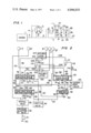
- FIG. 1 is a schematic diagram illustrating an automatic transmission employing the teachings of this invention.
- FIG. 2 is a circuit diagram showing an embodiment of the control apparatus of this invention.
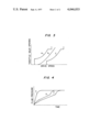
- FIG. 3 is a graph showing the relationships between the drive speed and the opening of the throttle valve of a carburetor during certain engine output and drive speed conditions of the vehicle.
- FIG. 4 is a graph showing the relationships between the lapse of time and the fluid pressure in certain segments of a control apparatus of this invention during a second-to-third shift operation.
- an automatic transmission employing the teachings of this invention, having an output shaft 2 of an engine 1 connected to an input shaft 5 of a speed-change gear mechanism through a torque converter 3 and a direct-linkage frictional engagement device such as a clutch 4 disposed in parallel to torque converter 3.
- the input shaft 5 is connected to an intermediate shaft 7 through a front clutch 6 and is also connected to another intermediate shaft 9 through a rear clutch 8.
- These intermediate shafts 7 and 9 are connected to an output shaft 10 of the speedchange gear mechanism through a planetary gear train 20 of the speed-change gear mechanism.
- This planetary gear train 20 may be a conventional one such as a Simpson type.
- Train 20 comprises sun gears 21 and 22 formed on intermediate shaft 9, pinions 23 and 24, carriers 25 and 26 rotatably pivoting pinions 23 and 24 respectively, a ring gear 27 connected to output shaft 10 and to carrier 26, and a ring gear 28 connected to intermediate shaft 7.
- a front brake 11 is mounted on drum 8a of rear clutch 8 and integrated with sun gears 21 and 22.
- a rear brake 12 is mounted on carrier 25.
- direct-linkage clutch 4 When direct-linkage clutch 4 is inoperable or relieved, the power from the engine is transmitted only through torque converter 3 to input shaft 5. When direct-linkage clutch 4 is operable or engaged, the power is transmitted through both torque converter 3 and direct-linkage clutch 4. However, since the transmission efficiency of torque converter 3 is much lower than that of direct-linkage clutch 4, the power is transmitted primarily and mechanically through direct-linkage clutch 4. The power transmitted to input shaft 5 is then transmitted to ring gear 28 of planetary gear unit 20 through intermediate shaft 7 by engagement of front clutch 6 during a forward drive condition. In this state, when carrier 25 is locked by the action of rear brake 12, a low speed rotation of the highest gear ratio of the speed-change gear mechanism is given to output shaft 10 and the first speed running condition is established.
- control apparatus comprises means for automatically and hydraulically controlling both the selective actuation of the speed-change gear mechanism in response to the engine output and vehicle speed, and the selective actuation of the direct-linkage frictional engagement device for directly linking the output shaft of the engine to the input shaft of the speed-change gear mechanism in response to a predetermined engine output and vehicle speed.
- fluid from a fluid reservoir 30 is pumped up by a pump 31 to a pressure adjustment valve 32 where the pressure of the fluid is adjusted to a prescribed level. Then, the fluid is introduced to a manual valve 33.
- a fluid passage 34 On the outlet side of manual valve 33 is a fluid passage 34 connected to a servomechanism 6' for actuating front clutch 6 and fluid passage 35 connected to a first-to-second shift valve 60.
- first-to-second valve 60 there is a fluid passage 36 connected to a servomechanism 12' for actuating rear brake 12 and a fluid passage 37 connected to a second-to-third shift valve 70.
- Fluid passages 38 and 39 from second-to-third shift valve 70 are connected to a servomechanism 11' for actuating front brake 11 and a servomechanism 8' for actuating rear clutch 8, respectively. Further, a fluid passage 40 branced from fluid passage 37 from first-to-second shift valve 60 is connected to a direct-linkage valve 80.
- a fluid passage 41 from direct-linkage valve 80 is connected to an interlock valve 90.
- a fluid passage 42 from interlock valve 90 is connected to a servomechamism 4' for actuating direct-linkage clutch 4.
- the fluid pressure from manual valve 33 is introduced to a governor valve 43 to generate a governor pressure corresponding to the vehicle drive speed and is guided to a throttle valve 44 to generate a throttle pressure corresponding to the opening of a throttle valve of a carburetor.
- the governor pressure from governor valve 43 is introduced to both shift valves 60 and 70, and direct-linkage valve 80 through the fluid passages 45 and 47, respectively.
- the throttle pressure from throttle valve 44 is introduced to both shift valves 60 to 70 and to direct-linkage valve 80 through the fluid passages 48 and 49, and 50, respectively, in such a manner that the governor pressure and the throttle pressure are fed to opposite sides of these valves.
- first-to-second shift valve 60 comprises a spool 62 urged by a spring 61 on one side, ports 63 and 67 connected to the fluid passages 45, 37 and 40, 35, 36, and 48, respectively, and drain ports 68 and 69.
- spool 62 When the governor pressure is low during a low drive speed condition of the vehicle, spool 62 is moved to the left by the force of spring 61 and the throttle pressure from throttle valve 44. Therefore, fluid passages 35 and 36 are connected by ports 65 and 66 and fluid passages 37 and 40 are connected to drain port 68 through port 64.
- the governor pressure is increased by an increase in the drive speed, spool 62 is moved to the right by action of the governor pressure from governor valve 43. Therefore, fluid passage 35 is connected to fluid passages 37 and 40 by port 64, and fluid passage 36 is connected to drain port 69 by port 66.
- direct-linkage valve 80 comprise a spool 82 urged by a spring 81 on one side, ports 83 to 86 connected to fluid passages 47, 41, 40, and 50, respectively, and a drain port 87. Similar to the situation for shift valves 60 and 70, direct-linkage valve 80 is actuated in response to the relationship between the governor pressure, corresponding to the drive speed, and the throttle pressure, corresponding to the opening of the throttle valve. Specifically, when the governor pressure is low during a low drive speed condition of the vehicle, spool 82 is moved to the right by the force of spring 81 and the throttle pressure from throttle valve 44. Therefore, passage 40 is blocked at port 85 and fluid passage 41 is connected to drain port 87 through port 84.
- fluid passage 39 extending between second-to-third shift valve 70 and servomechanism 8' for the third drive speed, there is disposed a portion of the pressure-reducing means including an orifice 105 and a check valve 106, connected in parallel to each other, and an accumulator 107.
- the fluid pressure to be fed to servomechanism 8' is reduced and controlled by the pressure-reducing means.
- Fluid passages 108 and 109 of the operation means are disposed to receive the non-reduced fluid pressure and the reduced fluid pressure on the second-to-third shift valve side and the servomechanism side, respectively, of the pressure-reducing means.
- fluid passages 103 and 108 on the second-to-third shift valve side of the pressure-reducing means and fluid passages 104 and 109 on the servomechanism side of the pressure-reducing means are connected to interlock valve 90, respectively, through direction changeover valves 110 and 111 and fluid passages 112 and 113 in such a manner that these fluid pressures act in opposite directions on the opposite sides of interlock valve 90.
- the operation means further includes orifice 114 and check valve 115, disposed in parallel to each other, and connected only to fluid passage 113 in such a manner that the reduced oil pressure in the fluid passage 104 and 109 on the servomechanism side of the pressure-reducing means is further reduced.
- interlock valve 90 comprises a spool 93 urged on its sides by springs 91 and 92 having an equal spring force, ports 94 to 97 connected to fluid passages 112, 42, 41, and 113, respectively, and a drain port 98.
- spool 93 When fluid pressures fed both from fluid passage 112 to port 94 and from fluid passage 113 to port 97 are zero or equal to each other, spool 93 is located at the center as shown in FIG. 2. Therefore, drain port 98 is closed and fluid passages 41 and 42 are connected through ports 95 and 96.
- spool 93 is moved to the right to block fluid passage 41 at port 96 and to connect fluid passage 42 to drain port 98 through port 95.
- fluid pressure is fed to servomechanism 6' through fluid passage 34 to allow front clutch 6 to make an engaging action, and also to fluid passage 35.
- the governor pressure from governor valve 43, corresponding to the drive speed, and the throttle pressure from throttle valve 44, corresponding to the opening of the throttle valve of the carburetor, are fed to both shift valves 60 and 70, and direct-linkage valve 80.
- fluid passages 35 and 36 are connected by means of first-to-second shift valve 60, and fluid pressure in fluid passage 35 is directly fed to servomechanism 12'. This causes actuation of rear brake 12 to establish the first speed in the automatic transmission.
- fluid passage 40 is connected to drain port 68 of first-to-second shift valve 60, and thus no fluid pressure is introduced to that passage. Accordingly, servomechanism 4' of front clutch 4 is not fed fluid pressure regardless of the operation of direct-linkage valve 80 or interlock valve 90, and direct-linkage clutch 4 is therefore relieved.
- the fluid pressure fed from fluid passage 38 to port 94 of interlock valve 90 through fluid passage 103, direction changeover valve 110 and fluid passage 112 is equal to the fluid pressure fed from fluid passage 38 to port 97 of interlock valve 90 through fluid passage 104, direction changeover valve 111, and fluid passage 112. Since equal pressures are acting on interlock valve 90, spool 93 is located at the center to connect fluid passages 41 and 42 to each other. Fluid pressure in passage 41 is therefore further fed to servomechanism 4' and direct-linkage clutch 4 is engaged to transmit the engine power mechanically in the automatic transmission.
- shift valve 60 and 70 are operable in a reverse manner because of the reduction of the drive speed.
- a shift from third speed to second speed causes the pressures on both ports 94 and 97 of interlock valve 90 to be exhausted.
- the fluid pressure supplied to servomechanism 11' through passage 38 by shift valve 70 is reduced and controlled by orifice 100 and accumulator 102. Since a difference occurs between the non-reduced pressure before and the reduced pressure after orifice 100 and accumulator 102, interlock valve 90 is actuated in the same manner as described above.
- direct-linkage clutch 4 is temporarily relieved.
- the direct-linkage clutch is relieved by the fluid pressure on servomechanism 4' being exhausted through drain port 87 by means of direct-linkage valve 80.
- the structure of the direct-linkage valve can be changed appropriately to actuate the direct-linkage frictional engagement device during operating conditions other than when the input-to-output speed ratio of the torque converter is constant.
Landscapes
- Engineering & Computer Science (AREA)
- General Engineering & Computer Science (AREA)
- Mechanical Engineering (AREA)
- Control Of Transmission Device (AREA)
- Control Of Fluid Gearings (AREA)
Applications Claiming Priority (2)
| Application Number | Priority Date | Filing Date | Title |
|---|---|---|---|
| JA50-45819 | 1975-04-17 | ||
| JP50045819A JPS589861B2 (ja) | 1975-04-17 | 1975-04-17 | ジドウヘンソクキノセイギヨソウチ |
Publications (1)
| Publication Number | Publication Date |
|---|---|
| US4046033A true US4046033A (en) | 1977-09-06 |
Family
ID=12729845
Family Applications (1)
| Application Number | Title | Priority Date | Filing Date |
|---|---|---|---|
| US05/614,700 Expired - Lifetime US4046033A (en) | 1975-04-17 | 1975-09-18 | Control apparatus for automatic transmission |
Country Status (2)
| Country | Link |
|---|---|
| US (1) | US4046033A (ja) |
| JP (1) | JPS589861B2 (ja) |
Cited By (20)
| Publication number | Priority date | Publication date | Assignee | Title |
|---|---|---|---|---|
| US4125038A (en) * | 1976-12-09 | 1978-11-14 | Mitsubishi Jukogyo Kabushiki Kaisha | Speed change gear in a hydraulic type automatic transmission |
| FR2436295A1 (fr) * | 1978-09-14 | 1980-04-11 | Honda Motor Co Ltd | Dispositif de commande d'une transmission de vehicule actionnee par de l'huile sous pression |
| FR2438211A1 (fr) * | 1978-10-05 | 1980-04-30 | Nissan Motor | Dispositif de prevention de blocage dans une transmission automatique de vehicule |
| US4246806A (en) * | 1978-01-16 | 1981-01-27 | Sundstrand Corporation | Multi-mode hydromechanical transmission shift system |
| US4291596A (en) * | 1978-01-10 | 1981-09-29 | Aisin-Warner Kabushiki Kaisha | Flow regulator valve in hydraulic control system for automatic transmission |
| US4313353A (en) * | 1978-10-13 | 1982-02-02 | Volkswagenwerk Aktiengesellschaft | Control system for an automatic transmission |
| US4349088A (en) * | 1978-11-07 | 1982-09-14 | Aisin-Warner Kabushiki Kaisha | Device for controlling a lock-up clutch in an automatic transmission with a lock-up clutch equipped fluid torque converter |
| DE3341160A1 (de) * | 1982-11-12 | 1984-05-17 | Honda Giken Kogyo K.K., Tokio/Tokyo | Sperre-steuereinrichtung fuer einen drehmomentwandler in einem fahrzeug-automatikgetriebe |
| US4457410A (en) * | 1980-06-10 | 1984-07-03 | Nissan Motor Co., Ltd. | Lock-up control system for a lock-up type automatic transmission of an automotive vehicle having an engine |
| US4474082A (en) * | 1981-09-11 | 1984-10-02 | Borg-Warner Corporation | Control system for power shifted transmission |
| DE3327518A1 (de) * | 1983-07-29 | 1985-02-14 | Nissan Motor Co., Ltd., Yokohama, Kanagawa | Steuerventilanordnung fuer ueberbrueckungskupplung |
| US4501173A (en) * | 1981-12-08 | 1985-02-26 | Volkswagenwerk Aktiengesellschaft | Fluid delivery control device for an automatic transmission |
| DE3435756A1 (de) * | 1983-09-28 | 1985-04-25 | Honda Giken Kogyo K.K., Tokio/Tokyo | Steuervorrichtung fuer eine direkt kuppelnde hydraulische kupplung in einem hydraulischen drehmomentwandler |
| US4539869A (en) * | 1980-07-07 | 1985-09-10 | Nissan Motor Co., Ltd. | Lock-up control system for lock-up type automatic transmission |
| US4561528A (en) * | 1982-05-20 | 1985-12-31 | Nissan Motor Co., Ltd. | Lock-up clutch control valve assembly |
| DE3522106A1 (de) * | 1984-06-20 | 1986-01-02 | Mazda Motor Corp., Hiroshima | Hydraulische steuerung fuer eine automatische kraftuebertragung |
| US4596322A (en) * | 1982-02-04 | 1986-06-24 | Honda Giken Kogyo Kabushiki Kaisha | Torque converter clutch control device for vehicle |
| US4602529A (en) * | 1982-06-25 | 1986-07-29 | Nissan Motor Co., Ltd. | Hydraulic control system for automatic transmission |
| US5507700A (en) * | 1992-12-15 | 1996-04-16 | Honda Giken Kogyo Kabushiki Kaisha | Hydraulic control unit for a vehicle automatic transmission |
| US5637053A (en) * | 1996-02-20 | 1997-06-10 | Ford Motor Company | Torque converter clutch lockout hydraulic system |
Citations (4)
| Publication number | Priority date | Publication date | Assignee | Title |
|---|---|---|---|---|
| US2903910A (en) * | 1953-02-05 | 1959-09-15 | Gen Motors Corp | Transmission and control system |
| US3053116A (en) * | 1958-04-25 | 1962-09-11 | Gen Motors Corp | Transmission |
| US3691872A (en) * | 1971-04-29 | 1972-09-19 | Gen Motors Corp | Transmission and controls |
| US3818783A (en) * | 1972-12-04 | 1974-06-25 | Gen Motors Corp | Manual and automatic shift controls for transmissions |
Family Cites Families (1)
| Publication number | Priority date | Publication date | Assignee | Title |
|---|---|---|---|---|
| US3857302A (en) * | 1973-06-25 | 1974-12-31 | Caterpillar Tractor Co | Transmission and speed controlled lock-up clutch |
-
1975
- 1975-04-17 JP JP50045819A patent/JPS589861B2/ja not_active Expired
- 1975-09-18 US US05/614,700 patent/US4046033A/en not_active Expired - Lifetime
Patent Citations (4)
| Publication number | Priority date | Publication date | Assignee | Title |
|---|---|---|---|---|
| US2903910A (en) * | 1953-02-05 | 1959-09-15 | Gen Motors Corp | Transmission and control system |
| US3053116A (en) * | 1958-04-25 | 1962-09-11 | Gen Motors Corp | Transmission |
| US3691872A (en) * | 1971-04-29 | 1972-09-19 | Gen Motors Corp | Transmission and controls |
| US3818783A (en) * | 1972-12-04 | 1974-06-25 | Gen Motors Corp | Manual and automatic shift controls for transmissions |
Cited By (22)
| Publication number | Priority date | Publication date | Assignee | Title |
|---|---|---|---|---|
| US4125038A (en) * | 1976-12-09 | 1978-11-14 | Mitsubishi Jukogyo Kabushiki Kaisha | Speed change gear in a hydraulic type automatic transmission |
| US4291596A (en) * | 1978-01-10 | 1981-09-29 | Aisin-Warner Kabushiki Kaisha | Flow regulator valve in hydraulic control system for automatic transmission |
| US4246806A (en) * | 1978-01-16 | 1981-01-27 | Sundstrand Corporation | Multi-mode hydromechanical transmission shift system |
| FR2436295A1 (fr) * | 1978-09-14 | 1980-04-11 | Honda Motor Co Ltd | Dispositif de commande d'une transmission de vehicule actionnee par de l'huile sous pression |
| US4253553A (en) * | 1978-09-14 | 1981-03-03 | Honda Giken Kogyo Kabushiki Kaisha | Control apparatus for an oil pressure operated transmission in automotive vehicle |
| FR2438211A1 (fr) * | 1978-10-05 | 1980-04-30 | Nissan Motor | Dispositif de prevention de blocage dans une transmission automatique de vehicule |
| US4307631A (en) * | 1978-10-05 | 1981-12-29 | Nissan Motor Company, Limited | Interlock preventive device for automatic power transmission |
| US4313353A (en) * | 1978-10-13 | 1982-02-02 | Volkswagenwerk Aktiengesellschaft | Control system for an automatic transmission |
| US4349088A (en) * | 1978-11-07 | 1982-09-14 | Aisin-Warner Kabushiki Kaisha | Device for controlling a lock-up clutch in an automatic transmission with a lock-up clutch equipped fluid torque converter |
| US4457410A (en) * | 1980-06-10 | 1984-07-03 | Nissan Motor Co., Ltd. | Lock-up control system for a lock-up type automatic transmission of an automotive vehicle having an engine |
| US4539869A (en) * | 1980-07-07 | 1985-09-10 | Nissan Motor Co., Ltd. | Lock-up control system for lock-up type automatic transmission |
| US4474082A (en) * | 1981-09-11 | 1984-10-02 | Borg-Warner Corporation | Control system for power shifted transmission |
| US4501173A (en) * | 1981-12-08 | 1985-02-26 | Volkswagenwerk Aktiengesellschaft | Fluid delivery control device for an automatic transmission |
| US4596322A (en) * | 1982-02-04 | 1986-06-24 | Honda Giken Kogyo Kabushiki Kaisha | Torque converter clutch control device for vehicle |
| US4561528A (en) * | 1982-05-20 | 1985-12-31 | Nissan Motor Co., Ltd. | Lock-up clutch control valve assembly |
| US4602529A (en) * | 1982-06-25 | 1986-07-29 | Nissan Motor Co., Ltd. | Hydraulic control system for automatic transmission |
| DE3341160A1 (de) * | 1982-11-12 | 1984-05-17 | Honda Giken Kogyo K.K., Tokio/Tokyo | Sperre-steuereinrichtung fuer einen drehmomentwandler in einem fahrzeug-automatikgetriebe |
| DE3327518A1 (de) * | 1983-07-29 | 1985-02-14 | Nissan Motor Co., Ltd., Yokohama, Kanagawa | Steuerventilanordnung fuer ueberbrueckungskupplung |
| DE3435756A1 (de) * | 1983-09-28 | 1985-04-25 | Honda Giken Kogyo K.K., Tokio/Tokyo | Steuervorrichtung fuer eine direkt kuppelnde hydraulische kupplung in einem hydraulischen drehmomentwandler |
| DE3522106A1 (de) * | 1984-06-20 | 1986-01-02 | Mazda Motor Corp., Hiroshima | Hydraulische steuerung fuer eine automatische kraftuebertragung |
| US5507700A (en) * | 1992-12-15 | 1996-04-16 | Honda Giken Kogyo Kabushiki Kaisha | Hydraulic control unit for a vehicle automatic transmission |
| US5637053A (en) * | 1996-02-20 | 1997-06-10 | Ford Motor Company | Torque converter clutch lockout hydraulic system |
Also Published As
| Publication number | Publication date |
|---|---|
| JPS51121659A (en) | 1976-10-25 |
| JPS589861B2 (ja) | 1983-02-23 |
Similar Documents
| Publication | Publication Date | Title |
|---|---|---|
| US4046033A (en) | Control apparatus for automatic transmission | |
| US4270636A (en) | Lock-up control system for a torque converter including a timing arrangement | |
| US3890856A (en) | Creep preventing hydraulic control circuit for vehicle automatic transmission | |
| US4095486A (en) | Device for controlling a lock-up clutch in an automatic transmission | |
| US4369865A (en) | Lock-up control system for a torque converter | |
| US3881372A (en) | Pressure reducing control device for the hydraulic control circuit of an automatic transmission | |
| EP0367551B1 (en) | Control system for torque converter of automatic transmission | |
| US3895542A (en) | Shift point stabilizing hydraulic control circuit for automatic transmission | |
| US3747439A (en) | Hydraulic control system for automatic transmissions | |
| US4955260A (en) | Hydraulic control system for transmission | |
| EP0779454A2 (en) | Continuously variable transmission | |
| US3651714A (en) | Hydraulic control system for an automatic transmission | |
| US4043227A (en) | Hydromechanical transmission | |
| US3908485A (en) | Automatic power transmission control system for reducing shocks when shifting from neutral to reverse drive conditions | |
| GB2031078A (en) | Line presure booster valve for an automatic power transmission | |
| US3593599A (en) | Hydraulic gear-shift control for automotive transmission systems | |
| US4108022A (en) | Device for controlling the speed shift operation of an automatic transmission | |
| US3525275A (en) | Braking downshift control valve system for an automatic power transmission mechanism | |
| US3703110A (en) | Hydraulic control system for an automatic transmission | |
| JPS6363783B2 (ja) | ||
| US3400613A (en) | Automatic transmission | |
| KR100222820B1 (ko) | 차량용 자동 변속기의 변속제어 시스템 | |
| US3731558A (en) | Line pressure regulating system for automatic power transmission | |
| JPS621141B2 (ja) | ||
| US5086671A (en) | Quick downshift control in hybrid continuously variable transmission |