US4045803A - Photocomposing apparatus - Google Patents
Photocomposing apparatus Download PDFInfo
- Publication number
- US4045803A US4045803A US05/600,960 US60096075A US4045803A US 4045803 A US4045803 A US 4045803A US 60096075 A US60096075 A US 60096075A US 4045803 A US4045803 A US 4045803A
- Authority
- US
- United States
- Prior art keywords
- mirror
- axis
- wide
- image
- angle lens
- Prior art date
- Legal status (The legal status is an assumption and is not a legal conclusion. Google has not performed a legal analysis and makes no representation as to the accuracy of the status listed.)
- Expired - Lifetime
Links
- 230000003287 optical effect Effects 0.000 claims abstract description 17
- 239000011159 matrix material Substances 0.000 claims abstract description 6
- 230000009471 action Effects 0.000 claims abstract description 3
- 238000006073 displacement reaction Methods 0.000 description 14
- 230000004048 modification Effects 0.000 description 4
- 238000012986 modification Methods 0.000 description 4
- 230000006872 improvement Effects 0.000 description 3
- 238000000034 method Methods 0.000 description 3
- 239000000835 fiber Substances 0.000 description 2
- 230000008569 process Effects 0.000 description 2
- 238000000926 separation method Methods 0.000 description 2
- 230000008859 change Effects 0.000 description 1
- 230000007423 decrease Effects 0.000 description 1
- 230000003247 decreasing effect Effects 0.000 description 1
- 230000001419 dependent effect Effects 0.000 description 1
- 230000000694 effects Effects 0.000 description 1
- 230000007246 mechanism Effects 0.000 description 1
Images
Classifications
-
- B—PERFORMING OPERATIONS; TRANSPORTING
- B41—PRINTING; LINING MACHINES; TYPEWRITERS; STAMPS
- B41B—MACHINES OR ACCESSORIES FOR MAKING, SETTING, OR DISTRIBUTING TYPE; TYPE; PHOTOGRAPHIC OR PHOTOELECTRIC COMPOSING DEVICES
- B41B21/00—Common details of photographic composing machines of the kinds covered in groups B41B17/00 and B41B19/00
- B41B21/16—Optical systems
- B41B21/24—Optical systems defining multiple optical paths
Definitions
- This invention relates to photocomposing apparatus for projecting selectable character images onto a photosensitive recording member.
- an optical projecting system for projecting optical images formed by illuminating selected characters on an adjustable character matrix, or font, to successive positions in an image line at the position of the recording member.
- the recording member is usually a roll of photosensitive film which is made to move intermittently past the image line, between the exposure of the film to successive rows of characters.
- a rotatable mirror may be used to reflect a beam in a swinging arc onto the surface of a film, but here the image plane is arcuate, having a centre of curvature on the axis of rotation of the mirror, and the image-receiving portion of the film must consequently be maintained with the correct curvature to prevent distortion at the edges of the film. This can be especially inconvenient when the image arc is across the width of a roll of sensitized film as is the usual practice, as mentioned above.
- Optical flatteners have been developed such as the fibre optic faceplate which is the subject of our copending U.S. Patent application Ser. No. 400826.
- This device is a plate made from optic fibres, and has a curved surface onto which character images are projected, and a plane surface against which the film is held.
- the fibres are arranged to counteract focal distortion and preferably also spacial distortion. These are, however, expensive to make and call for high precision in the arrangement of the optic fibres to ensure accurate positioning of the character image on the flat output face of the fibre optic plate.
- the object of the present invention is to use standard optical elements to achieve a substantially flat image field.
- photocomposing apparatus comprising a projection system for projecting optical images selected from a character matrix onto a photosensitive recording member by way of a mirror which is rotatable to displace projected images with respect to the recording member, and including a wide-angle lens for focussing the optical images onto a substantially flat image plane coincident with the recording member, means being provided for producing a first fixed image which provides, by the action of said rotatable mirror, an object for the wide angle lens which is selectively positionable in a substantially flat object plane.
- wide angle lens is meant one which will accept rays of light diverging considerably from its axis, so that an image may be formed where a normal lens would not have an acceptance angle large enough to form an image.
- Means for rotating the rotatable mirror preferably comprise a stepwise operable motor, by which, after each exposure of the film to a selected character, the mirror is rotated by a fine, adjustable step, so as to project the next succeeding character to a position on the film adjacent the previous character.
- the size of the steps may be adjusted so as to alter the spacing of the characters.
- the projection system may include a zoom lens system by which the selected illuminated characters are focussed to produce the first fixed image at a position on or near to the optical axis of the wide angle lens, and so that, in its mean central position, the mirror is perpendicular to the beam incident thereon as measured in a plane normal to the axis of rotation of the rotatable mirror.
- the first fixed image may be positioned by means of a mirror fixed obliquely to the optical axis of the zoom lens and tilted relative to the rotatable mirror so that the beam reflected by the rotatable mirror into the wide-angle lens is not obstructed by the fixed mirror.
- the rotatable mirror may be arranged so that in its central mean position, that is its position when a character is being projected to the middle of a character line, it is not perpendicular to the beam from the first fixed image as measured in a plane normal to the axis of rotation of the mirror.
- a fixed mirror for separating the zoom lens and the wide-angle lens systems is then unnecessary.
- the rotatable mirror may be arranged to reflect light from the first fixed image into the lens, such that rotation of the mirror causes movement of a second, movable, virtual image produced by the rotatable mirror, in a substantially flat object plane transverse to the axis of the lens.
- the wide-angle lens thereby produces images in a flat image plane coincident with the surface of the film.
- the axis of rotation of the mirror may be at the mirror, or may be in front of the mirror. In the latter case, as will be explained hereinafter, an improvement in the overall flatness of the plane of the movable virtual image may be achieved.
- Adjustment of the zoom lens system alters the size of the images projected onto the film.
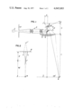
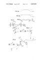
- FIG. 1 is a plan view of the optical system of a photocomposing apparatus in accordance with the invention
- FIG. 2 illustrates a modification of the system illustrated in FIG. 1;
- FIGS. 3a to 3c illustrate the shape of an image plane obtained in the systems of FIGS. 1 and 2;
- FIG. 4 illustrates a mechanical system for controlling the rotatable mirror of the optical systems of FIGS. 1 and 2;
- FIG. 5 illustrates a further modification of the system illustrated in FIG. 1;
- FIG. 6 illustrates a modification of the system illustrated by FIG. 5, and the shape of an image plane obtained thereby.
- a light source 1 illuminates a selected character in a fixed size array of characters 2 in a font array, or character matrix by any known method.
- a zoom lens system 3 creates an image I of the character at a suitable size of the line of type being composed.
- a mirror 4 arranged at an oblique angle to the axis of the zoom lens system, places the image I on the axis of a wide-angle lens 5 so that the light travels away from the lens.
- a mirror 6 is mounted on a rotating member such as a stepping motor (not shown) and is shown rotated by an angle ⁇ from the normal to the axis of lens 5.
- a virtual image of the character image I is created behind the mirror 6 at I 1 , such that its displacement 1 from the axis of lens 5 is a function of the separation d of image I from the mirror and the angle ⁇ of orientation of the mirror.
- the mirrors 4 and 6 are relatively tilted with reference to a normal to the plane of the figure so that light from the virtual image I 1 passes over the top of mirror 4 and into the lens 5 at an angle dependent on the degree of tilt of mirror 6 to form a real image 8 at the plane of a surface of a light sensitive element 7.
- the property of a wide angle lens is to produce a nominally flat field even under heterochromatic light conditions.
- the light source is monochromatic (such as laser light) then the lens may produce a substantially flatter field.
- the axis of rotation 9 is at the mirror, and substantially (taking into account the aforementioned relative tilt between mirrors 4 and 6) in the plane thereof the focus of the virtual image I 1 is a circle of radius d.
- the angle of turn of the mirror is necessarily relatively small in order to maintain the plane of image I 1 as flat as possible.
- FIG. 2 An improvement is achieved by moving the axis of rotation in front of the mirror.
- This arrangement is illustrated generally in FIG. 2, in which the distance from the rotational axis to the mirror is (1+k)d. It can be shown that as the axis 9 begins to move away from the mirror, the image field becomes flatter.
- the image I 1 displaces from its central position, in a sense away from the mirror as the mirror tilts away from its central mean position, but as the mirror swings further the displacement decreases, and drops to zero at points 10. Further tilting of the mirror displaces the image towards the mirror, as shown in FIG. 3c.
- the ratio of maximum image deviation E (see FIG. 3c) to the line length, i.e. the distance between the two points 10 in FIG. 3c is (1-Cos ⁇ 1 ) 2 /8Sin ⁇ 1 , where ⁇ 1 is the maximum mirror tilt.
- the wide angle lens system will generally have a depth of field which will be greater than this, so that the images 8 will be in sharp focus in the plane of element 7.
- a further improvement over the above-described embodiment and modifications thereof, is to avoid the necessity of providing the mirror 4, which serves to separate the zoom lens system and the wide-angle lens, but which necessitates the aforementioned tilting of the mirror 6 to project the beam reflected therefrom over the mirror 4, causing distortion of the character shape and placement.
- This is achieved, as shown in FIG. 5, by disposing the mirror 6 to be oblique to the beam from image I in its central mean position when the axis of rotation 9 is in the plane of the mirror, as in FIG. 5, the image I 1 lies in an arcuate image field as in the arrangement of FIG. 1.
- a flatter image field may be produced by a suitable choice of the axis of rotation in front of the mirror.
- the maximum deviation E, for a line length of 2 inches is 0.010 inch.
- the stepping motor is operated such that the mirror 6 rotates through angles of displacement which do not vary as the separation 1 of the image I 1 from the axis of lens 5 varies, the spacing of the characters is greater at the edges of the film 7 than in the centre zone, since the value of 1 is proportional to tan ⁇ .
- the displacement and the final image displacement ml may thus be made to change by equal steps only when the stepping motor operates in accordance with a tangent function. This may be achieved by applying a correction as the displacement 1 increases, when operating the motor in stepwise fashion in accord with our British Pat. No. 1,178,834.
- a computer used in the type setting process may be programmed to make decreasing angular increments of the mirror as the displacement 1 increases.
- a linearly movable rack 11 has a toothed end portion which engages a rotatable pinion 12 coupled to a stepping motor whose spindle rotates in a succession of equal incremental steps.
- the rack 11 is thus displaced longitudinally in corresponding equal linear steps.
- a pin 13 attached to the rack slides in an elongate slot in a mirror lever 14 which is arranged to rotate about an axis 15 remote from the slot.
- the mirror 6 is mounted on the lever 14 normal to the longitudinal axis thereof at the appropriate point in accordance with the selected value for k.
- h is the perpendicular distance from the axis 15 to the lever 14
- s is the variable distance between the pin 13 and the line normal to the lever 14 and passage through the axis 15
- ⁇ is the angle of tilt of the mirror about axis 15
- tan ⁇ is proportional to s.
- the displacement 1 of image I 1 is proportional to tan ⁇ , and so 1 is proportional to s; that is to say when this mechanical arrangement is employed to rotate the mirror 6, displacement of the image I and of image 8, is proportional to the displacement of the rack 11, and the uniform rotational stepping of the pinion 12 will produce uniform linear displacements in the final character image position.
- the functional relationship between the mirror rotation and the character displacement will not, in the general case be a simple tangential one, and would have to be evaluated for each particular arrangement, and stored, preferably by a computer.
- the virtual image I 1 is not normal to the axis of the lens for all displacements ⁇ of the mirror, but rather is inclined to the normal thereto at an angle of 2 ⁇ . If the real width of the character is W, then its apparent width will be WCos2 ⁇ , and the twist relative to the normal to the lens axis will necessitate and additional depth of field of the wide angle lens of WSin2 ⁇ . However, in practice, the image is of small finite size and any blurring at the edges of the character and variation in the character sizes along the character line is of no great significance.
Landscapes
- Projection-Type Copiers In General (AREA)
- Lenses (AREA)
Applications Claiming Priority (2)
| Application Number | Priority Date | Filing Date | Title |
|---|---|---|---|
| GB3465674 | 1974-08-06 | ||
| UK34656/74 | 1974-08-06 |
Publications (1)
| Publication Number | Publication Date |
|---|---|
| US4045803A true US4045803A (en) | 1977-08-30 |
Family
ID=10368355
Family Applications (1)
| Application Number | Title | Priority Date | Filing Date |
|---|---|---|---|
| US05/600,960 Expired - Lifetime US4045803A (en) | 1974-08-06 | 1975-08-01 | Photocomposing apparatus |
Country Status (3)
| Country | Link |
|---|---|
| US (1) | US4045803A (OSRAM) |
| DE (1) | DE2534883A1 (OSRAM) |
| FR (1) | FR2281220A1 (OSRAM) |
Cited By (3)
| Publication number | Priority date | Publication date | Assignee | Title |
|---|---|---|---|---|
| US5204485A (en) * | 1991-10-28 | 1993-04-20 | Lombardi Donald G | Multi-axle drum beater and pedal apparatus |
| US20080156967A1 (en) * | 2006-12-29 | 2008-07-03 | Samsung Electro-Mechanics Co., Ltd. | Optical movement sensing system |
| CN112419826A (zh) * | 2020-12-16 | 2021-02-26 | 上海索验智能科技有限公司 | 虚拟仿真腹腔镜手术内窥镜操作训练方法及系统 |
Citations (3)
| Publication number | Priority date | Publication date | Assignee | Title |
|---|---|---|---|---|
| US3687025A (en) * | 1970-05-04 | 1972-08-29 | Harris Intertype Corp | Image spacing system |
| US3733979A (en) * | 1970-07-14 | 1973-05-22 | Monotype Corp Ltd | Photocomposing apparatus |
| US3881801A (en) * | 1973-09-19 | 1975-05-06 | Eltra Corp | Optical scanning system |
Family Cites Families (2)
| Publication number | Priority date | Publication date | Assignee | Title |
|---|---|---|---|---|
| FR1497986A (fr) * | 1966-10-28 | 1967-10-13 | Dispositif pour la transmission optique de signes d'écriture | |
| FR1499754A (fr) * | 1966-11-15 | 1967-10-27 | Linotype Gmbh | Dispositif de composition héliographique |
-
1975
- 1975-08-01 US US05/600,960 patent/US4045803A/en not_active Expired - Lifetime
- 1975-08-05 DE DE19752534883 patent/DE2534883A1/de active Pending
- 1975-08-05 FR FR7524332A patent/FR2281220A1/fr active Granted
Patent Citations (3)
| Publication number | Priority date | Publication date | Assignee | Title |
|---|---|---|---|---|
| US3687025A (en) * | 1970-05-04 | 1972-08-29 | Harris Intertype Corp | Image spacing system |
| US3733979A (en) * | 1970-07-14 | 1973-05-22 | Monotype Corp Ltd | Photocomposing apparatus |
| US3881801A (en) * | 1973-09-19 | 1975-05-06 | Eltra Corp | Optical scanning system |
Cited By (6)
| Publication number | Priority date | Publication date | Assignee | Title |
|---|---|---|---|---|
| US5204485A (en) * | 1991-10-28 | 1993-04-20 | Lombardi Donald G | Multi-axle drum beater and pedal apparatus |
| US5421235A (en) * | 1991-10-28 | 1995-06-06 | Drum Workshop, Inc. | Multi-axle drum beater and pedal apparatus |
| US20080156967A1 (en) * | 2006-12-29 | 2008-07-03 | Samsung Electro-Mechanics Co., Ltd. | Optical movement sensing system |
| US7723669B2 (en) * | 2006-12-29 | 2010-05-25 | Samsung Electro-Mechanics Co., Ltd. | Optical movement sensing system |
| CN112419826A (zh) * | 2020-12-16 | 2021-02-26 | 上海索验智能科技有限公司 | 虚拟仿真腹腔镜手术内窥镜操作训练方法及系统 |
| CN112419826B (zh) * | 2020-12-16 | 2023-05-23 | 上海索验智能科技有限公司 | 虚拟仿真腹腔镜手术内窥镜操作训练方法及系统 |
Also Published As
| Publication number | Publication date |
|---|---|
| FR2281220A1 (fr) | 1976-03-05 |
| FR2281220B1 (OSRAM) | 1979-05-11 |
| DE2534883A1 (de) | 1976-02-19 |
Similar Documents
| Publication | Publication Date | Title |
|---|---|---|
| US4475787A (en) | Single facet wobble free scanner | |
| JPS63136017A (ja) | 光ビ−ム走査装置 | |
| US4127777A (en) | Method for automatic adjustment | |
| JPS62125646A (ja) | 光ビ−ム位置ぎめ装置 | |
| US3687025A (en) | Image spacing system | |
| US5475523A (en) | Disk for light beam recording device and light beam recording device | |
| US4045803A (en) | Photocomposing apparatus | |
| US3801180A (en) | Optical deflection systems | |
| US3733979A (en) | Photocomposing apparatus | |
| US3873180A (en) | Light beam scanning system with scan angle demagnification | |
| US3881801A (en) | Optical scanning system | |
| US4573758A (en) | Beam deflection mechanism | |
| US3827063A (en) | Multilens photocomposing mechanism | |
| JP2696364B2 (ja) | 走査式光学装置のモニター機構 | |
| US5438613A (en) | X-ray analysis apparatus and scanning unit suitable for use in such an apparatus | |
| US3450464A (en) | Optical anamorphic systems for justification of printed text lines | |
| CA1297713C (en) | Scanning apparatus and support | |
| JPS5815767B2 (ja) | ヒカリビ−ムソウサホセイコウガクケイ | |
| US4027312A (en) | Optical scanning apparatus and method for manufacturing cathode ray tubes | |
| JPH06331913A (ja) | 2ビーム光走査装置 | |
| JP2659137B2 (ja) | レーザ光走査装置 | |
| US4571065A (en) | Scale factor changing mechanism for copying machine | |
| US3556647A (en) | Continuous film movement motion picture camera | |
| GB2091900A (en) | Device for applying radiation at adjustable angles, monochromators | |
| JP2756681B2 (ja) | 光軸微調装置 |
Legal Events
| Date | Code | Title | Description |
|---|---|---|---|
| AS | Assignment |
Owner name: MONOTYPE CORPORATION PUBLIC LIMITED COMPANY THE Free format text: CHANGE OF NAME;ASSIGNOR:MONOTYPE CORPORATION LIMITED THE;REEL/FRAME:004609/0136 Effective date: 19860213 |