US4045687A - Circuit arrangement for evaluating the electrical output signals of a detector for thickness changes in a fuel injection line - Google Patents
Circuit arrangement for evaluating the electrical output signals of a detector for thickness changes in a fuel injection line Download PDFInfo
- Publication number
- US4045687A US4045687A US05/716,220 US71622076A US4045687A US 4045687 A US4045687 A US 4045687A US 71622076 A US71622076 A US 71622076A US 4045687 A US4045687 A US 4045687A
- Authority
- US
- United States
- Prior art keywords
- output
- detector
- schmitt trigger
- rectifier
- evaluating
- Prior art date
- Legal status (The legal status is an assumption and is not a legal conclusion. Google has not performed a legal analysis and makes no representation as to the accuracy of the status listed.)
- Expired - Lifetime
Links
- 238000002347 injection Methods 0.000 title claims abstract description 30
- 239000007924 injection Substances 0.000 title claims abstract description 30
- 239000000446 fuel Substances 0.000 title claims abstract description 9
- 238000000034 method Methods 0.000 claims abstract description 14
- 230000002238 attenuated effect Effects 0.000 description 1
- 238000002485 combustion reaction Methods 0.000 description 1
- 230000003247 decreasing effect Effects 0.000 description 1
- 238000010586 diagram Methods 0.000 description 1
- 238000011835 investigation Methods 0.000 description 1
- 238000005259 measurement Methods 0.000 description 1
- 230000035939 shock Effects 0.000 description 1
- 230000001960 triggered effect Effects 0.000 description 1
- XLYOFNOQVPJJNP-UHFFFAOYSA-N water Substances O XLYOFNOQVPJJNP-UHFFFAOYSA-N 0.000 description 1
Images
Classifications
-
- F—MECHANICAL ENGINEERING; LIGHTING; HEATING; WEAPONS; BLASTING
- F02—COMBUSTION ENGINES; HOT-GAS OR COMBUSTION-PRODUCT ENGINE PLANTS
- F02M—SUPPLYING COMBUSTION ENGINES IN GENERAL WITH COMBUSTIBLE MIXTURES OR CONSTITUENTS THEREOF
- F02M65/00—Testing fuel-injection apparatus, e.g. testing injection timing ; Cleaning of fuel-injection apparatus
- F02M65/003—Measuring variation of fuel pressure in high pressure line
-
- F—MECHANICAL ENGINEERING; LIGHTING; HEATING; WEAPONS; BLASTING
- F02—COMBUSTION ENGINES; HOT-GAS OR COMBUSTION-PRODUCT ENGINE PLANTS
- F02D—CONTROLLING COMBUSTION ENGINES
- F02D41/00—Electrical control of supply of combustible mixture or its constituents
- F02D41/30—Controlling fuel injection
- F02D41/3005—Details not otherwise provided for
-
- G—PHYSICS
- G01—MEASURING; TESTING
- G01L—MEASURING FORCE, STRESS, TORQUE, WORK, MECHANICAL POWER, MECHANICAL EFFICIENCY, OR FLUID PRESSURE
- G01L9/00—Measuring steady of quasi-steady pressure of fluid or fluent solid material by electric or magnetic pressure-sensitive elements; Transmitting or indicating the displacement of mechanical pressure-sensitive elements, used to measure the steady or quasi-steady pressure of a fluid or fluent solid material, by electric or magnetic means
- G01L9/08—Measuring steady of quasi-steady pressure of fluid or fluent solid material by electric or magnetic pressure-sensitive elements; Transmitting or indicating the displacement of mechanical pressure-sensitive elements, used to measure the steady or quasi-steady pressure of a fluid or fluent solid material, by electric or magnetic means by making use of piezoelectric devices, i.e. electric circuits therefor
-
- F—MECHANICAL ENGINEERING; LIGHTING; HEATING; WEAPONS; BLASTING
- F02—COMBUSTION ENGINES; HOT-GAS OR COMBUSTION-PRODUCT ENGINE PLANTS
- F02D—CONTROLLING COMBUSTION ENGINES
- F02D41/00—Electrical control of supply of combustible mixture or its constituents
- F02D41/20—Output circuits, e.g. for controlling currents in command coils
- F02D2041/202—Output circuits, e.g. for controlling currents in command coils characterised by the control of the circuit
- F02D2041/2055—Output circuits, e.g. for controlling currents in command coils characterised by the control of the circuit with means for determining actual opening or closing time
-
- F—MECHANICAL ENGINEERING; LIGHTING; HEATING; WEAPONS; BLASTING
- F02—COMBUSTION ENGINES; HOT-GAS OR COMBUSTION-PRODUCT ENGINE PLANTS
- F02D—CONTROLLING COMBUSTION ENGINES
- F02D2200/00—Input parameters for engine control
- F02D2200/02—Input parameters for engine control the parameters being related to the engine
- F02D2200/06—Fuel or fuel supply system parameters
- F02D2200/0602—Fuel pressure
-
- F—MECHANICAL ENGINEERING; LIGHTING; HEATING; WEAPONS; BLASTING
- F02—COMBUSTION ENGINES; HOT-GAS OR COMBUSTION-PRODUCT ENGINE PLANTS
- F02D—CONTROLLING COMBUSTION ENGINES
- F02D41/00—Electrical control of supply of combustible mixture or its constituents
- F02D41/20—Output circuits, e.g. for controlling currents in command coils
- F02D41/2096—Output circuits, e.g. for controlling currents in command coils for controlling piezoelectric injectors
-
- F—MECHANICAL ENGINEERING; LIGHTING; HEATING; WEAPONS; BLASTING
- F02—COMBUSTION ENGINES; HOT-GAS OR COMBUSTION-PRODUCT ENGINE PLANTS
- F02M—SUPPLYING COMBUSTION ENGINES IN GENERAL WITH COMBUSTIBLE MIXTURES OR CONSTITUENTS THEREOF
- F02M2200/00—Details of fuel-injection apparatus, not otherwise provided for
- F02M2200/21—Fuel-injection apparatus with piezoelectric or magnetostrictive elements
Definitions
- This invention relates to a circuit arrangement for evaluating the electrical output signals of a detector for thickness changes in a fuel injection line under the influence of an injection process in general, and more particularly to such a circuit for evaluating the rapid pressure variations generated when an injection valve is closed.
- An injection time detector for internal combustion engines having fuel injection which comprises a transducer attached to the outside of the fuel injection line for picking up the elastic changes of the outside diameter of the line caused by the injection process and converting them into an electrical signal is disclosed in copending application Ser. No. 715,850.
- the injection process lasts a certain time. It is therefore important to select from the electrical signal representing the entire injection process a part which always appears, within the overall process, at the same point in the injection process, regardless of the duration of the injection.
- One possibility for this purpose is the beginning of the injection process.
- the relatively flat slope of the injection pressure at the beginning of the injection process is, however, disadvantageous and makes such a choice questionable.
- a further problem in measuring is that, even if the detector is attached only to the injection line of one cylinder, signals above the general noise level from the injection lines of the other cylinders are also transmitted to the detector, even if attenuated.
- the waveform is a sequence of relatively high frequency (>500 Hz) pressure waves with, first, a high and then rapidly decreasing amplitude.
- Another object is to discriminate the signal of one cylinder from the signals of the other cylinders.
- these objects are achieved by connecting an a-c voltage amplifier, a highpass filter and a rectifier in series, with a peak value storage device and a Schmitt trigger connected in parallel and each connected to the output of the rectifier, the output of the peak value storage device being connected as a reference input to the Schmitt trigger and a one shot multivibrator being connected to the output of the Schmitt trigger.
- the a-c voltage amplifier amplifies the pressure waves caused by the closing of the injection valve in the fuel column, i.e., the electrical output signal of the detector representing these pressure waves.
- the highpass filter which has a cut off frequency of about 500 Hz, the characteristic vibrations are filtered out and the output signal of the highpass filter is finally rectified in rectifiers for further homogenizing the signal.
- This signal is fed on the one hand to the peak value storage device and, on the other hand, to a Schmitt trigger, the reference input of which is connected to the output of the peak value storage device.
- This arrangement prevents triggering by interference waves from other injection lines of the engine below an adjustable reference level.
- the one shot is triggered by the output of the Schmitt trigger and delivers an output signal which exactly marks the end of the injection process.
- the detector having its output signal evaluated is a piezoelectric detector, it must also be possible to measure the base voltage which is caused by the clamping force of the piezoelectric element.
- the a-c voltage amplifier is preceded by a differential amplifier, at the output of which this base voltage can be measured.
- the clamping force of the piezoelectric element Prior to each measurement, should be set so that there is a uniform base voltage.
- the lower cut off frequency of the highpass filter is advantageously chosen at approximately 500 Hz.
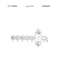
- the single FIGURE is a block diagram of the circuit arrangement of the present invention.
- the output leads of a piezoelectric detector 1 are connected to the two inputs of a differential amplifier 2.
- the base voltage of the piezo detector can be measured at the output of the differential amplifier 2 for adjusting the clamping force of the piezoelectric element.
- the output of the differential amplifier 2 is connected to the input of an a-c voltage amplifier 3, which further amplifies only the a-c component of the output voltage of the differential amplifier.
- the output of the a-c voltage amplifier 3 is connected to the input of a highpass filter 4, which passes all frequencies of the a-c voltage signal above about 500 Hz and heavily attenuates the portion of the signal below this frequency.
- the output of the highpass filter 4 is fed to the input of a rectifier 5, which rectifies the amplified waves to homogenize the signal further.
- the output of the rectifier 5 is connected on the one hand to the input of a peak value storage device 6 and, on the other hand, to the input of a Schmitt trigger 7.
- the output of the peak value storage device 6 is connected to a reference input of the Schmitt trigger 7. It is ensured in this manner that the Schmitt trigger 7 can respond only if its input voltage corresponds to a reference level which is a preset ratio derived from the same signal.
- the output of the Schmitt trigger is connected to the input of a one shot multivibrator, at the output of which a signal exactly marking the end of the injection process can be taken off.
Landscapes
- Engineering & Computer Science (AREA)
- Chemical & Material Sciences (AREA)
- Combustion & Propulsion (AREA)
- Mechanical Engineering (AREA)
- General Engineering & Computer Science (AREA)
- Physics & Mathematics (AREA)
- General Physics & Mathematics (AREA)
- Measuring Fluid Pressure (AREA)
- Measurement Of Length, Angles, Or The Like Using Electric Or Magnetic Means (AREA)
- Length Measuring Devices With Unspecified Measuring Means (AREA)
Abstract
A circuit arrangement for evaluating the electrical output signals of a detector for thickness changes in a fuel injection line under the influence of an injection process comprising a series circuit connected to output terminals of the detector and including a differential amplifier, an a-c voltage amplifier, a highpass filter and a rectifier with a peak value storage device and a Schmitt trigger each connected in parallel to the output of the rectifier, the output of the peak value storage device being connected as a reference input of the Schmitt trigger, and a one shot multivibrator connected to the output of the Schmitt trigger.
Description
This invention relates to a circuit arrangement for evaluating the electrical output signals of a detector for thickness changes in a fuel injection line under the influence of an injection process in general, and more particularly to such a circuit for evaluating the rapid pressure variations generated when an injection valve is closed.
An injection time detector for internal combustion engines having fuel injection which comprises a transducer attached to the outside of the fuel injection line for picking up the elastic changes of the outside diameter of the line caused by the injection process and converting them into an electrical signal is disclosed in copending application Ser. No. 715,850. The injection process lasts a certain time. It is therefore important to select from the electrical signal representing the entire injection process a part which always appears, within the overall process, at the same point in the injection process, regardless of the duration of the injection. One possibility for this purpose is the beginning of the injection process. The relatively flat slope of the injection pressure at the beginning of the injection process is, however, disadvantageous and makes such a choice questionable. A further problem in measuring is that, even if the detector is attached only to the injection line of one cylinder, signals above the general noise level from the injection lines of the other cylinders are also transmitted to the detector, even if attenuated.
Investigations of the entire injection process have shown that a pressure waveform similar to a water shock ("hammer") caused by the rapid closing of the injection valves, occurs in the fuel. This waveform is also transmitted to the walls of the fuel injection line. The waveform is a sequence of relatively high frequency (>500 Hz) pressure waves with, first, a high and then rapidly decreasing amplitude.
It is an object of the present invention to evaluate an electrical signal that corresponds to the pressure waves at the end of the injection process described above.
Another object is to discriminate the signal of one cylinder from the signals of the other cylinders.
According to the invention, these objects are achieved by connecting an a-c voltage amplifier, a highpass filter and a rectifier in series, with a peak value storage device and a Schmitt trigger connected in parallel and each connected to the output of the rectifier, the output of the peak value storage device being connected as a reference input to the Schmitt trigger and a one shot multivibrator being connected to the output of the Schmitt trigger.
The a-c voltage amplifier amplifies the pressure waves caused by the closing of the injection valve in the fuel column, i.e., the electrical output signal of the detector representing these pressure waves. In the highpass filter, which has a cut off frequency of about 500 Hz, the characteristic vibrations are filtered out and the output signal of the highpass filter is finally rectified in rectifiers for further homogenizing the signal. This signal is fed on the one hand to the peak value storage device and, on the other hand, to a Schmitt trigger, the reference input of which is connected to the output of the peak value storage device. This arrangement prevents triggering by interference waves from other injection lines of the engine below an adjustable reference level. The one shot is triggered by the output of the Schmitt trigger and delivers an output signal which exactly marks the end of the injection process.
If the detector having its output signal evaluated is a piezoelectric detector, it must also be possible to measure the base voltage which is caused by the clamping force of the piezoelectric element. For this purpose the a-c voltage amplifier is preceded by a differential amplifier, at the output of which this base voltage can be measured. Prior to each measurement, the clamping force of the piezoelectric element should be set so that there is a uniform base voltage. The lower cut off frequency of the highpass filter is advantageously chosen at approximately 500 Hz.
The single FIGURE is a block diagram of the circuit arrangement of the present invention.
As illustrated, the output leads of a piezoelectric detector 1 are connected to the two inputs of a differential amplifier 2. By means of an instrument, not shown for the sake of simplicity, the base voltage of the piezo detector can be measured at the output of the differential amplifier 2 for adjusting the clamping force of the piezoelectric element. The output of the differential amplifier 2 is connected to the input of an a-c voltage amplifier 3, which further amplifies only the a-c component of the output voltage of the differential amplifier. The output of the a-c voltage amplifier 3 is connected to the input of a highpass filter 4, which passes all frequencies of the a-c voltage signal above about 500 Hz and heavily attenuates the portion of the signal below this frequency. The output of the highpass filter 4 is fed to the input of a rectifier 5, which rectifies the amplified waves to homogenize the signal further. The output of the rectifier 5 is connected on the one hand to the input of a peak value storage device 6 and, on the other hand, to the input of a Schmitt trigger 7. The output of the peak value storage device 6 is connected to a reference input of the Schmitt trigger 7. It is ensured in this manner that the Schmitt trigger 7 can respond only if its input voltage corresponds to a reference level which is a preset ratio derived from the same signal. The output of the Schmitt trigger is connected to the input of a one shot multivibrator, at the output of which a signal exactly marking the end of the injection process can be taken off.
Claims (4)
1. Apparatus for evaluating the electrical output signals of a detector for thickness changes in a fuel injection line due to the influence of the injection process, such as the rapid pressure variations generated when an injection valve is closed, comprising:
a. the series connection of an a-c voltage amplifier responsive to said detected signals at its input, a highpass filter and a rectifier responsive to said a-c voltage output;
b. a peak value storage device having the output of said rectifier as its input;
c. a Schmitt trigger, also having as its input the output of said rectifier, the output of said peak value storage device being connected as a reference input to the Schmitt trigger; and
d. a one shot multivibrator connected to the output of said Schmitt trigger.
2. Apparatus according to claim 1, and further including a differential amplifier coupled between the detector and said a-c voltage amplifier.
3. Apparatus according to claim 2, wherein said highpass filter has a lower cut off frequency of about 500 Hz.
4. Apparatus according to claim 1, wherein said highpass filter has a lower cut off frequency of about 500 Hz.
Applications Claiming Priority (2)
| Application Number | Priority Date | Filing Date | Title |
|---|---|---|---|
| DE19752539194 DE2539194A1 (en) | 1975-09-03 | 1975-09-03 | CIRCUIT ARRANGEMENT FOR EVALUATION OF ELECTRICAL OUTPUT SIGNALS OF A DETECTOR FOR THICKNESS OF A FUEL INJECTION LINE |
| DT2539194 | 1975-09-03 |
Publications (1)
| Publication Number | Publication Date |
|---|---|
| US4045687A true US4045687A (en) | 1977-08-30 |
Family
ID=5955507
Family Applications (1)
| Application Number | Title | Priority Date | Filing Date |
|---|---|---|---|
| US05/716,220 Expired - Lifetime US4045687A (en) | 1975-09-03 | 1976-08-20 | Circuit arrangement for evaluating the electrical output signals of a detector for thickness changes in a fuel injection line |
Country Status (6)
| Country | Link |
|---|---|
| US (1) | US4045687A (en) |
| JP (1) | JPS5232357A (en) |
| DE (1) | DE2539194A1 (en) |
| FR (1) | FR2323182A1 (en) |
| IT (1) | IT1067838B (en) |
| SE (1) | SE7609368L (en) |
Cited By (3)
| Publication number | Priority date | Publication date | Assignee | Title |
|---|---|---|---|---|
| US4562362A (en) * | 1982-10-18 | 1985-12-31 | Tektronix, Inc. | Automatic trigger sensitivity adjustment circuit |
| US5128973A (en) * | 1989-10-27 | 1992-07-07 | Stanley Electric Co., Ltd. | Circuit system for preventing measuring device from being erroneously operated |
| WO2001073282A1 (en) * | 2000-03-24 | 2001-10-04 | Robert Bosch Gmbh | Method for determining the rail pressure of an injection valve having an piezoelectric actuator |
Families Citing this family (5)
| Publication number | Priority date | Publication date | Assignee | Title |
|---|---|---|---|---|
| US4187720A (en) * | 1978-11-06 | 1980-02-12 | Deere & Company | Fuel line injection sensor |
| US4421088A (en) * | 1980-07-03 | 1983-12-20 | Lucas Industries Limited | Fuel system for compression ignition engine |
| DE3118425A1 (en) * | 1981-05-09 | 1982-12-09 | Robert Bosch Gmbh, 7000 Stuttgart | DEVICE FOR DETECTING THE AMOUNT OF FUEL SUPPLIED TO THE COMBUSTION SPACES OF A DIESEL ENGINE |
| DE3612808A1 (en) * | 1986-04-16 | 1987-10-22 | Bosch Gmbh Robert | ARRANGEMENT FOR DETECTING THE START OF SPRAYING IN A DIESEL INTERNAL COMBUSTION ENGINE |
| FR2919025A1 (en) * | 2007-07-20 | 2009-01-23 | Rene Girard | Electric voltage peak selecting method for combustion engine, involves preventing access to new voltage stored in memory after determined value during delay time, if new voltage is supplied, and resetting memory to zero at end of delay time |
Citations (4)
| Publication number | Priority date | Publication date | Assignee | Title |
|---|---|---|---|---|
| US2952811A (en) * | 1956-06-14 | 1960-09-13 | Itt | Modulation synchronizing pulse generator |
| US3800164A (en) * | 1969-01-02 | 1974-03-26 | Us Navy | Redundant logic circuit |
| US3968447A (en) * | 1972-12-29 | 1976-07-06 | Commissariat A L'energie Atomique | Method of amplitude-frequency conversion and a converter which operates in accordance with said method |
| US4004239A (en) * | 1974-07-20 | 1977-01-18 | Ferranti, Limited | Discrimination circuit for isolating disturbance signals which are superimposed on D.C. pedestals |
-
1975
- 1975-09-03 DE DE19752539194 patent/DE2539194A1/en not_active Ceased
-
1976
- 1976-08-20 US US05/716,220 patent/US4045687A/en not_active Expired - Lifetime
- 1976-08-24 SE SE7609368A patent/SE7609368L/en unknown
- 1976-08-31 IT IT26684/76A patent/IT1067838B/en active
- 1976-09-02 FR FR7626492A patent/FR2323182A1/en active Granted
- 1976-09-03 JP JP51105650A patent/JPS5232357A/en active Pending
Patent Citations (4)
| Publication number | Priority date | Publication date | Assignee | Title |
|---|---|---|---|---|
| US2952811A (en) * | 1956-06-14 | 1960-09-13 | Itt | Modulation synchronizing pulse generator |
| US3800164A (en) * | 1969-01-02 | 1974-03-26 | Us Navy | Redundant logic circuit |
| US3968447A (en) * | 1972-12-29 | 1976-07-06 | Commissariat A L'energie Atomique | Method of amplitude-frequency conversion and a converter which operates in accordance with said method |
| US4004239A (en) * | 1974-07-20 | 1977-01-18 | Ferranti, Limited | Discrimination circuit for isolating disturbance signals which are superimposed on D.C. pedestals |
Cited By (4)
| Publication number | Priority date | Publication date | Assignee | Title |
|---|---|---|---|---|
| US4562362A (en) * | 1982-10-18 | 1985-12-31 | Tektronix, Inc. | Automatic trigger sensitivity adjustment circuit |
| US5128973A (en) * | 1989-10-27 | 1992-07-07 | Stanley Electric Co., Ltd. | Circuit system for preventing measuring device from being erroneously operated |
| WO2001073282A1 (en) * | 2000-03-24 | 2001-10-04 | Robert Bosch Gmbh | Method for determining the rail pressure of an injection valve having an piezoelectric actuator |
| US6712047B2 (en) | 2000-03-24 | 2004-03-30 | Robert Bosch Gmbh | Method for determining the rail pressure of an injector having a piezoelectrical actuator |
Also Published As
| Publication number | Publication date |
|---|---|
| FR2323182A1 (en) | 1977-04-01 |
| SE7609368L (en) | 1977-03-04 |
| JPS5232357A (en) | 1977-03-11 |
| FR2323182B3 (en) | 1979-05-25 |
| DE2539194A1 (en) | 1977-03-10 |
| IT1067838B (en) | 1985-03-21 |
Similar Documents
| Publication | Publication Date | Title |
|---|---|---|
| US4061116A (en) | Knock level control apparatus for an internal combustion engine | |
| US2340714A (en) | Method and apparatus for sound analysis | |
| US8312760B2 (en) | Knock detection device for a cobustion engine and a method for a combustion knock detection | |
| US3731527A (en) | Fuel injection transducer and timing system | |
| US4045687A (en) | Circuit arrangement for evaluating the electrical output signals of a detector for thickness changes in a fuel injection line | |
| GB1408385A (en) | Engine test equipment | |
| US3238765A (en) | Apparatus for determining the combustion quality of a fuel | |
| GB1589913A (en) | Methods and devices for detecting the commencement of injection by injection valves | |
| GB2189885A (en) | Turbulent flow monitoring | |
| CA1069178A (en) | Testing compression in engines from starter motor current waveform | |
| US4423621A (en) | Knocking detector | |
| US4444042A (en) | Engine-knock detection method and apparatus | |
| GB2089986A (en) | Detecting fuel injector opening | |
| US3576526A (en) | Detection of knock in internal combustion engines | |
| GB2035560A (en) | Apparatus for detecting and analysing acoustic and ultrasonic signals in hollow bodies | |
| US4420968A (en) | Undesirable combustion characteristic detection apparatus | |
| US4329871A (en) | Undesirable combustion characteristic detection apparatus | |
| US4523458A (en) | Injector tester | |
| US3183708A (en) | Method and apparatus for metering pressure phenomena in internal combustion engines | |
| US3540262A (en) | Knock and rumble detector for internal combustion engines | |
| US3430136A (en) | Test equipment for identification and location of electrical faults in fluid-filled electric apparatus | |
| US3389599A (en) | Engine-cylinder pressure indicators | |
| DE4132096A1 (en) | Knocking detector for IC engine - has comparator for signals generated b vibration detector and arithmetic processor providing reference | |
| US3201972A (en) | Knock detection instrument | |
| JPS6127582B2 (en) |