US4045110A - Electrical connector housings - Google Patents
Electrical connector housings Download PDFInfo
- Publication number
- US4045110A US4045110A US05/727,550 US72755076A US4045110A US 4045110 A US4045110 A US 4045110A US 72755076 A US72755076 A US 72755076A US 4045110 A US4045110 A US 4045110A
- Authority
- US
- United States
- Prior art keywords
- housing
- strip
- passageways
- housing part
- extending
- Prior art date
- Legal status (The legal status is an assumption and is not a legal conclusion. Google has not performed a legal analysis and makes no representation as to the accuracy of the status listed.)
- Expired - Lifetime
Links
- 239000011810 insulating material Substances 0.000 claims 3
- 230000013011 mating Effects 0.000 claims 1
- 239000012777 electrically insulating material Substances 0.000 abstract description 3
- 239000000463 material Substances 0.000 description 2
- 238000010276 construction Methods 0.000 description 1
- 230000000694 effects Effects 0.000 description 1
- 238000005192 partition Methods 0.000 description 1
- 229920003023 plastic Polymers 0.000 description 1
- 239000004033 plastic Substances 0.000 description 1
Images

Classifications
-
- H—ELECTRICITY
- H01—ELECTRIC ELEMENTS
- H01R—ELECTRICALLY-CONDUCTIVE CONNECTIONS; STRUCTURAL ASSOCIATIONS OF A PLURALITY OF MUTUALLY-INSULATED ELECTRICAL CONNECTING ELEMENTS; COUPLING DEVICES; CURRENT COLLECTORS
- H01R13/00—Details of coupling devices of the kinds covered by groups H01R12/70 or H01R24/00 - H01R33/00
- H01R13/40—Securing contact members in or to a base or case; Insulating of contact members
- H01R13/42—Securing in a demountable manner
- H01R13/436—Securing a plurality of contact members by one locking piece or operation
-
- H—ELECTRICITY
- H01—ELECTRIC ELEMENTS
- H01R—ELECTRICALLY-CONDUCTIVE CONNECTIONS; STRUCTURAL ASSOCIATIONS OF A PLURALITY OF MUTUALLY-INSULATED ELECTRICAL CONNECTING ELEMENTS; COUPLING DEVICES; CURRENT COLLECTORS
- H01R13/00—Details of coupling devices of the kinds covered by groups H01R12/70 or H01R24/00 - H01R33/00
- H01R13/40—Securing contact members in or to a base or case; Insulating of contact members
- H01R13/42—Securing in a demountable manner
- H01R13/422—Securing in resilient one-piece base or case, e.g. by friction; One-piece base or case formed with resilient locking means
- H01R13/4223—Securing in resilient one-piece base or case, e.g. by friction; One-piece base or case formed with resilient locking means comprising integral flexible contact retaining fingers
Abstract
An electrical connector housing includes two housing parts of electrically insulating material and a strip carrying a plurality of locking lances. The strip is assembled in one of the housing parts so that an individual locking lance extends into a cavity defined by aligned passageways in the two housing parts for resiliently engaging an electrical contact when received in the cavity.
Description
The present invention relates to electrical connector housings.
It is known, for example, from U.S. Pat. No. 3,648,213 for an electrical connector housing of electrically insulating material to have a passageway extending between opposed faces of the connector housing for receiving an electrical contact. A stiffly flexible locking lance extends into the passageway from one wall of the passageway which lance locks the electrical connector in the passageway. The lance is moulded integrally with the connector housing.
The mould tool required for producing a connector housing having a passageway extending between opposed faces and a locking lance extending from one wall of the passageway can be complicated and expensive to manufacure. This particular difficulty is accentuated where the electrical connector housing is intended to house a plurality of electrical contacts each in an individual passage-way and locked in the passageway by an individual locking lance.
According to the present invention, an electrical connector housing for a plurality of electrical contacts is chacterised by first and second housing parts of electrically insulated material and a strip carrying a plurality of locking lances. Each housing part includes cooperating means for latching the first and second housing parts together and each housing part has a row of spaced, parallel passageways. The passageways of the housing parts are aligned to define a row of cavities extending between opposed faces of the connector housing for receiving electrical contacts. The strip is assembled in the first housing part so that an individual locking lance extends into each cavity defined by the passageways of the first and second housing parts for resiliently engaging an electrical contact when received in the cavity.
Since the locking lances and the strip are manufactured separately of the housing parts, the mould tools required for the housing part are simple in construction. Furthermore, the strip and locking lances are easily assembled to the first housing part and require no special skills on the part of an assembler.
In a preferred embodiment, the strip and the locking lances are moulded as an integral one-piece item. In electrical connector housings where many electrical contacts are received in rows and columns of cavities the provision of locking lances carried by strips each strip being associated with a row, simplifies mould design with consequence economic advantages.
An embodiment of the invention will now be described, by way of example, reference being made to the Figures of the accompanying diagrammatic drawings in which:
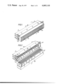
FIG. 1 is a perspective view of an electrical connector housing;
FIG. 2 is a perspective view similar to FIG. 1 but with two housing parts separated to reveal the interior of one housing part;
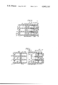
FIG. 3 is a cross-section on the line III--III of FIG. 1;
FIG. 4 is a cross-section similar to FIG. 3 but showing the two housing parts separated;
FIG. 5 is a cross-section on the line V--V of FIG. 3;
FIG. 6 is a cross-sectional detail of the electrical connector housing of FIG. 1;
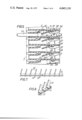
FIG. 7 is a plan view of a strip carrying a plurality of locking lances; and
FIG. 8 is a perspective view of a portion of the strip of FIG. 7.
As shown, an electrical connector housing 1 for a plurality of electrical contacts 13 (only one shown in FIG. 5), comprises first and second housing parts 2, 3 of electrically insulating material and a strip 11 carrying a plurality of locking lances 10.
The first housing part 2 includes a body portion 20 through which pass a plurality of spaced, parallel passageways 22 forwardly from a rear face 8. The passageways 22 are arranged in three rows. Each passageway 22 is separated from adjacent passageways 22 by side walls 24 and adjacent rows are separated by partitions 26. A member 28 extends from each side wall 24 into an associated passageway 22. The member 28 is formed with a forwardly facing recess 30. A forward portion of each side wall 24 is of reduced height and, in effect, the forward portions of each side wall of each row define a channel 32 communicating with each of the passageways 22 of the row.
Contact stablilizing ribs 34 extend along the length of each passageway 22 adjacent a side wall 24.
A hood 36 extends forwardly from the body portion 20 and has upper and lower (as shown) forwardly facing shoudlers 38. Polarising ribs 39,40 extend forwardly along each corner of the hood 36, the ribs being profiled and extending outwardly a short distance from the hood 36. The hood has two sets of four through holes 5 along its upper and lower (as shown) sides. The forward face of the hood 36 is open to permit entry of a rear portion of the second housing part 3 as will be explained.
The second housing part 3 has a body through which pass a plurality of spaced, parallel passageways 50 rearwardly from a forward surface 7. The upper and lower (as shown in FIGS. 1, 3 and 4) sides of the housing part 3 have polarising channels 41,42 which cooperate respecting with the ribs 39,40 on the hood 36 of the housing part 2. The upper and lower sides also have rearwardly facing shoulders 44,46 and detents 4 arranged in two sets of four for cooperation with the holes 5.
The passageways 50 are arranged in three rows and when the housing parts 2,3 are releasably latched together as will be explained, each passageway 50 is aligned with a passageway 22 to define a cavity 6.
Referring in particular to FIGS. 7 and 8, a plurality of equi-spaced, generally parallel, resilient locking lances 10 are carried by an elongate strip 11. The strip 11 and the locking lances 10 are moulded as an integral one-piece item of plastics material. Each locking lance 10 extends from one surface of the substantially flat strip 11 and a major portion of each lance 10 extends laterally outwardly from one side of the strip 11. However, a minor portion 12 of each lance 10 extends laterally outwardly from the opposite side of the strip 11. The minor portion 12 of each lance 10 is stepped to define a protuberance 13.
On assembling the electrical connector housing 1, a strip 11 is inserted into each channel 32 communicating with a row of passageway 22 via the open forward face of the hood 36 so that each protuberance 13 is received in a recess 30. Next, the rear portion of the housing part 3 is inserted into the housing part 2 via the open forward face of the hood 36 and is releasably latched to the housing part 2 by means of the cooperating detents 4 and holes 5 so that an individual locking lance 10 extends into each cavity 6 defined by the aligned passageways 22,50. The cooperating polarising ribs 39,40 and channels 41,42 prevent incorrect assembly of the housing parts 2 and 3 together. When the housing parts 2,3 are correctly assembled, the shoulder 44 on the housing part 3 engages the shoulder 38 of the housing part 2 and the shoulder 46 engages the free end face of the hood 36. It can be seen that the rear end of the housing part 3 prevents the strips 11 from being accidentally moved from their respective channels 32.
Referring especially to FIG. 5, there is shown an electrical contact 13 received in a cavity 6 and maintained in the cavity 6 by a resilient locking lance 10. The contact 13 is positioned in the cavity 6 via the rear face 8 of the electrical connector housing 1.
An advantage of the electrical connector housing described above is that the use of a strip of locking lances which can be easily and rapidly assembled to the housing part 2 eliminates the need for a complicated mould design for the connector housing where each cavity has its own individual locking lance moulded in one-piece with the wall of the cavity.
Although detents 4 and holes 5 have been described for releasably latching the housing parts 2,3 together other cooperating means can be used including means for permanently maintaining the housing parts together.
Claims (4)
1. An electrical connector housing for a plurality of electrical contacts comprising:
a. first and second housing parts of electrical insulating material and being adapted for mating one with the other, each housing part having at least one row of spaced parallel passageways, the passageways of the housing parts being aligned to define at least one row of cavities extending between opposed faces of the housings when mated for receiving electrical contacts;
b. a channel in the first housing part extending across the passageways;
c. an elongated strip of insulating material having a plurality of spaced apart lances projecting outward form one edge, said strip positioned in the channel with individual lances extending into the cavities in the row for resiliently engaging and retaining electrical contacts which may be inserted into the cavities.
2. An electrical connector housing comprising first and second housing parts of insulating material and a strip carrying a plurality of locking lances extending from one surface of the strip, a major portion of each lance extending laterally outwardly from one side of the strip, but a minor portion of each lance extending laterally outwardly from the opposite side of the strip, the locking lances being generally parallel and equi-spaced along the length of the strip, and each minor portion being stepped to define a protuberance, each housing part including cooperating means for latching the first and second housing parts together, each housing part having a row of spaced, parallel passageways, the passageways of the housing parts being aligned to define a row of cavities extending between opposed faces of the connector housing for receiving electrical contacts, the strip being assembled in the first housing part so that an individual locking lance extends into each cavity defined by the passageways of the first and second housing parts for resiliently engaging an electrical contact when received in the cavity.
3. An electrical connector housing as claimed in claim 2, in which the strip is received in a channel in the first housing part, the channel communicating with each passageway of the row of passageways in the first housing part, the protuberance on each locking lance being received in a recess in the respective pasageway of the first housing part to locate the locking lance in the cavity.
4. An electrical connector housing as claimed in claim 3, in which the first housing part has a body portion through which the spaced, parallel passageways pass forwardly from a rear surface and a hood extending forwardly from the body portion, the hood receiving a rear portion of the second housing, the hood and the rear portion having co-operating detents and holes for latching releasably the housing parts together.
Applications Claiming Priority (2)
| Application Number | Priority Date | Filing Date | Title |
|---|---|---|---|
| UK40727/75 | 1975-10-04 | ||
| GB40727/75A GB1490907A (en) | 1975-10-04 | 1975-10-04 | Electrical connector housings |
Publications (1)
| Publication Number | Publication Date |
|---|---|
| US4045110A true US4045110A (en) | 1977-08-30 |
Family
ID=10416323
Family Applications (1)
| Application Number | Title | Priority Date | Filing Date |
|---|---|---|---|
| US05/727,550 Expired - Lifetime US4045110A (en) | 1975-10-04 | 1976-09-28 | Electrical connector housings |
Country Status (14)
| Country | Link |
|---|---|
| US (1) | US4045110A (en) |
| JP (1) | JPS60748B2 (en) |
| AR (1) | AR208256A1 (en) |
| AU (1) | AU503528B2 (en) |
| CA (1) | CA1056939A (en) |
| CH (1) | CH607364A5 (en) |
| DE (2) | DE7631033U1 (en) |
| ES (1) | ES451842A1 (en) |
| FI (1) | FI762789A (en) |
| FR (1) | FR2326791A1 (en) |
| GB (1) | GB1490907A (en) |
| IT (1) | IT1068459B (en) |
| NL (1) | NL7610258A (en) |
| SE (1) | SE411819B (en) |
Cited By (19)
| Publication number | Priority date | Publication date | Assignee | Title |
|---|---|---|---|---|
| US4147400A (en) * | 1978-02-21 | 1979-04-03 | Amp Incorporated | Contact retention device |
| US4580341A (en) * | 1982-12-30 | 1986-04-08 | Precision Mecanique Labinal | Electrical connector |
| US4602839A (en) * | 1985-01-28 | 1986-07-29 | General Motors Corporation | Electrical connector with multifunction lock means |
| US4740177A (en) * | 1987-02-09 | 1988-04-26 | Standex International Corporation | Cluster assembly with locking tabs |
| US4832616A (en) * | 1982-07-06 | 1989-05-23 | General Motors Corporation | Electrical connector with conductor seal lock |
| US4898548A (en) * | 1985-09-20 | 1990-02-06 | Molex Incorporated | Connector assembly |
| US4921448A (en) * | 1988-05-06 | 1990-05-01 | Yazaki Corporation | Connector terminal retainer construction |
| DE4105470A1 (en) * | 1990-02-21 | 1991-08-22 | Yazaki Corp | ELECTRICAL CONNECTOR WITH A CONNECTION POINT CONNECTOR WITH A STABILIZER |
| US5108319A (en) * | 1990-10-12 | 1992-04-28 | Yazaki Corporation | Connector with a terminal locking device |
| US5186662A (en) * | 1990-05-30 | 1993-02-16 | Amp Incorporated | Double locking-type electrical connector |
| US5292261A (en) * | 1988-08-30 | 1994-03-08 | Yazaki Corporation | Terminal retainer for connector |
| EP0723316A2 (en) * | 1995-01-20 | 1996-07-24 | Sumitomo Wiring Systems, Ltd. | Plate connector |
| US5643009A (en) * | 1996-02-26 | 1997-07-01 | The Whitaker Corporation | Electrical connector having a pivot lock |
| US20060148331A1 (en) * | 2003-07-19 | 2006-07-06 | Leopold Kostal Gmbh & Co., Kg | Chamber housing for forming an electrical plug-in connection part |
| ES2297985A1 (en) * | 2005-08-10 | 2008-05-01 | Bsh Electrodomesticos España, S.A. | Electrical connector for rotary switch, has one axis for operation of some electrical contacts on both sides of plane that passes through shaft where group of electrical cable is connected |
| US20140378005A1 (en) * | 2012-03-09 | 2014-12-25 | Yazaki Corporation | Connector |
| US20160141788A1 (en) * | 2014-11-13 | 2016-05-19 | Tyco Electronics Corporation | Electrical connector |
| US10276964B2 (en) * | 2015-08-31 | 2019-04-30 | Harting Electric Gmbh & Co. Kg | Contact carrier |
| US11283209B2 (en) * | 2017-08-09 | 2022-03-22 | Te Connectivity Germany Gmbh | Connector housing for an electrical connector |
Families Citing this family (12)
| Publication number | Priority date | Publication date | Assignee | Title |
|---|---|---|---|---|
| US4283100A (en) * | 1979-12-27 | 1981-08-11 | Western Electric Company, Inc. | Jumper plug |
| IT1154773B (en) * | 1980-04-15 | 1987-01-21 | Ca Ma Sas | MODULAR MULTIPLE CONNECTOR FOR SUPPORTING CONTACT HOLDER PLINES TO BE APPLIED TO CONNECTOR HOLDER STRIPS IN ELECTRONIC SYSTEMS |
| DE3020903A1 (en) * | 1980-06-02 | 1981-12-17 | Robert Bosch Gmbh, 7000 Stuttgart | MULTIPOLE CONNECTOR |
| US4548461A (en) * | 1983-12-19 | 1985-10-22 | Amp Incorporated | Connector having improved contact retainers |
| DE3103455C2 (en) * | 1981-02-02 | 1984-03-22 | Siemens AG, 1000 Berlin und 8000 München | Electrical connector, in particular for data technology |
| JPS603103U (en) * | 1983-06-22 | 1985-01-11 | 住友ゴム工業株式会社 | Pneumatic radial tire that prevents bead damage |
| JPH0659766B2 (en) * | 1983-09-14 | 1994-08-10 | 住友ゴム工業株式会社 | Radial tires for heavy loads |
| DE4008721C1 (en) * | 1990-03-19 | 1991-09-05 | Deutsche Forschungsanstalt Fuer Luft- Und Raumfahrt Ev, 5300 Bonn, De | |
| JPH07114131B2 (en) * | 1990-05-16 | 1995-12-06 | 矢崎総業株式会社 | connector |
| JPH0434875A (en) * | 1990-05-30 | 1992-02-05 | Amp Japan Ltd | Double lock type electrical connector |
| US5044991A (en) * | 1990-11-05 | 1991-09-03 | Molex Incorporated | Electrical connector with terminal position assurance component |
| FR2923090A1 (en) | 2007-10-31 | 2009-05-01 | C & K Components Soc Par Actio | MINIATURE ELECTRICAL CONNECTOR WITH EXTRACTIBLE CONTACT ELEMENTS AND ASSOCIATED TOOL FOR UNLOCKING AND EXTRACTING CONTACTS |
Citations (1)
| Publication number | Priority date | Publication date | Assignee | Title |
|---|---|---|---|---|
| US3165369A (en) * | 1962-08-13 | 1965-01-12 | Itt | Retention system for electrical contacts |
-
1975
- 1975-10-04 GB GB40727/75A patent/GB1490907A/en not_active Expired
-
1976
- 1976-01-01 AR AR264882A patent/AR208256A1/en active
- 1976-09-13 AU AU17698/76A patent/AU503528B2/en not_active Expired
- 1976-09-15 NL NL7610258A patent/NL7610258A/en not_active Application Discontinuation
- 1976-09-16 IT IT27269/76A patent/IT1068459B/en active
- 1976-09-22 JP JP51113202A patent/JPS60748B2/en not_active Expired
- 1976-09-24 ES ES451842A patent/ES451842A1/en not_active Expired
- 1976-09-28 US US05/727,550 patent/US4045110A/en not_active Expired - Lifetime
- 1976-09-28 CH CH1223576A patent/CH607364A5/xx not_active IP Right Cessation
- 1976-09-30 FI FI762789A patent/FI762789A/fi not_active Application Discontinuation
- 1976-10-01 FR FR7629661A patent/FR2326791A1/en active Granted
- 1976-10-01 SE SE7610924A patent/SE411819B/en unknown
- 1976-10-01 CA CA262,562A patent/CA1056939A/en not_active Expired
- 1976-10-04 DE DE7631033U patent/DE7631033U1/en not_active Expired
- 1976-10-04 DE DE19762644779 patent/DE2644779A1/en not_active Withdrawn
Patent Citations (1)
| Publication number | Priority date | Publication date | Assignee | Title |
|---|---|---|---|---|
| US3165369A (en) * | 1962-08-13 | 1965-01-12 | Itt | Retention system for electrical contacts |
Cited By (23)
| Publication number | Priority date | Publication date | Assignee | Title |
|---|---|---|---|---|
| US4147400A (en) * | 1978-02-21 | 1979-04-03 | Amp Incorporated | Contact retention device |
| US4832616A (en) * | 1982-07-06 | 1989-05-23 | General Motors Corporation | Electrical connector with conductor seal lock |
| US4580341A (en) * | 1982-12-30 | 1986-04-08 | Precision Mecanique Labinal | Electrical connector |
| US4602839A (en) * | 1985-01-28 | 1986-07-29 | General Motors Corporation | Electrical connector with multifunction lock means |
| US4898548A (en) * | 1985-09-20 | 1990-02-06 | Molex Incorporated | Connector assembly |
| US4740177A (en) * | 1987-02-09 | 1988-04-26 | Standex International Corporation | Cluster assembly with locking tabs |
| US4921448A (en) * | 1988-05-06 | 1990-05-01 | Yazaki Corporation | Connector terminal retainer construction |
| US5292261A (en) * | 1988-08-30 | 1994-03-08 | Yazaki Corporation | Terminal retainer for connector |
| DE4105470A1 (en) * | 1990-02-21 | 1991-08-22 | Yazaki Corp | ELECTRICAL CONNECTOR WITH A CONNECTION POINT CONNECTOR WITH A STABILIZER |
| US5186662A (en) * | 1990-05-30 | 1993-02-16 | Amp Incorporated | Double locking-type electrical connector |
| US5108319A (en) * | 1990-10-12 | 1992-04-28 | Yazaki Corporation | Connector with a terminal locking device |
| EP0723316A2 (en) * | 1995-01-20 | 1996-07-24 | Sumitomo Wiring Systems, Ltd. | Plate connector |
| EP0723316A3 (en) * | 1995-01-20 | 1997-12-17 | Sumitomo Wiring Systems, Ltd. | Plate connector |
| US5643009A (en) * | 1996-02-26 | 1997-07-01 | The Whitaker Corporation | Electrical connector having a pivot lock |
| US20060148331A1 (en) * | 2003-07-19 | 2006-07-06 | Leopold Kostal Gmbh & Co., Kg | Chamber housing for forming an electrical plug-in connection part |
| US7390228B2 (en) | 2003-07-19 | 2008-06-24 | Leopold Kostal Gmbh & Co. Kg | Chamber housing for forming an electrical plug-in connection part |
| ES2297985A1 (en) * | 2005-08-10 | 2008-05-01 | Bsh Electrodomesticos España, S.A. | Electrical connector for rotary switch, has one axis for operation of some electrical contacts on both sides of plane that passes through shaft where group of electrical cable is connected |
| US20140378005A1 (en) * | 2012-03-09 | 2014-12-25 | Yazaki Corporation | Connector |
| US9385460B2 (en) * | 2012-03-09 | 2016-07-05 | Yazaki Corporation | Connector |
| US20160141788A1 (en) * | 2014-11-13 | 2016-05-19 | Tyco Electronics Corporation | Electrical connector |
| US9484660B2 (en) * | 2014-11-13 | 2016-11-01 | Tyco Electronics Corporation | Electrical connector |
| US10276964B2 (en) * | 2015-08-31 | 2019-04-30 | Harting Electric Gmbh & Co. Kg | Contact carrier |
| US11283209B2 (en) * | 2017-08-09 | 2022-03-22 | Te Connectivity Germany Gmbh | Connector housing for an electrical connector |
Also Published As
| Publication number | Publication date |
|---|---|
| JPS5245083A (en) | 1977-04-08 |
| AR208256A1 (en) | 1976-12-09 |
| AU1769876A (en) | 1978-03-23 |
| FR2326791A1 (en) | 1977-04-29 |
| NL7610258A (en) | 1977-04-06 |
| FR2326791B1 (en) | 1981-10-09 |
| SE411819B (en) | 1980-02-04 |
| FI762789A (en) | 1977-04-05 |
| SE7610924L (en) | 1977-04-05 |
| AU503528B2 (en) | 1979-09-06 |
| JPS60748B2 (en) | 1985-01-10 |
| DE7631033U1 (en) | 1977-04-21 |
| ES451842A1 (en) | 1977-12-16 |
| CH607364A5 (en) | 1978-12-15 |
| CA1056939A (en) | 1979-06-19 |
| GB1490907A (en) | 1977-11-02 |
| DE2644779A1 (en) | 1977-04-14 |
| IT1068459B (en) | 1985-03-21 |
Similar Documents
| Publication | Publication Date | Title |
|---|---|---|
| US4045110A (en) | Electrical connector housings | |
| US4368939A (en) | Modular connector housing | |
| US5122080A (en) | Electrical connector | |
| US4695112A (en) | Printed circuit board, edgeboard connector therefor | |
| US4319799A (en) | Electrical connector with group terminal lock | |
| US5066252A (en) | Retainer for metal terminal of electric connector | |
| KR970001616B1 (en) | Solder post alignment and retention system | |
| US4959023A (en) | Electrical connector | |
| US3325771A (en) | Electrical connector module with adjustable polarization | |
| US5358427A (en) | Connector having a dual terminal-fastening structure | |
| US5443403A (en) | Composite electrical connector assembly with snap-in housing | |
| US6106340A (en) | Electrical connector with deflectable secondary | |
| EP0644619B1 (en) | Method and apparatus for double securing a terminal within a connector | |
| GB2104735A (en) | Electrical connector | |
| US3905673A (en) | Header block | |
| US9257773B2 (en) | Connector | |
| US5033980A (en) | Electrical connector with a double locking structure for terminals | |
| US4066325A (en) | Electrical connector for printed circuit board | |
| US3486159A (en) | Connectors for use with flexible printed circuits | |
| CN109167201B (en) | Electrical connector | |
| US6386904B2 (en) | Electrical connector having terminal incomplete insertion recognizing structure | |
| US4530561A (en) | Edge connector | |
| GB1443288A (en) | Female connector | |
| US4168874A (en) | Connector having improved panel mounting means | |
| US5468162A (en) | Locking connector |