US4044997A - Seat ring notch for gate valve guide rail - Google Patents
Seat ring notch for gate valve guide rail Download PDFInfo
- Publication number
- US4044997A US4044997A US05/721,947 US72194776A US4044997A US 4044997 A US4044997 A US 4044997A US 72194776 A US72194776 A US 72194776A US 4044997 A US4044997 A US 4044997A
- Authority
- US
- United States
- Prior art keywords
- seat member
- valve seat
- gate
- valve
- seat
- Prior art date
- Legal status (The legal status is an assumption and is not a legal conclusion. Google has not performed a legal analysis and makes no representation as to the accuracy of the status listed.)
- Expired - Lifetime
Links
Images
Classifications
-
- F—MECHANICAL ENGINEERING; LIGHTING; HEATING; WEAPONS; BLASTING
- F16—ENGINEERING ELEMENTS AND UNITS; GENERAL MEASURES FOR PRODUCING AND MAINTAINING EFFECTIVE FUNCTIONING OF MACHINES OR INSTALLATIONS; THERMAL INSULATION IN GENERAL
- F16K—VALVES; TAPS; COCKS; ACTUATING-FLOATS; DEVICES FOR VENTING OR AERATING
- F16K3/00—Gate valves or sliding valves, i.e. cut-off apparatus with closing members having a sliding movement along the seat for opening and closing
- F16K3/02—Gate valves or sliding valves, i.e. cut-off apparatus with closing members having a sliding movement along the seat for opening and closing with flat sealing faces; Packings therefor
- F16K3/12—Gate valves or sliding valves, i.e. cut-off apparatus with closing members having a sliding movement along the seat for opening and closing with flat sealing faces; Packings therefor with wedge-shaped arrangements of sealing faces
-
- F—MECHANICAL ENGINEERING; LIGHTING; HEATING; WEAPONS; BLASTING
- F16—ENGINEERING ELEMENTS AND UNITS; GENERAL MEASURES FOR PRODUCING AND MAINTAINING EFFECTIVE FUNCTIONING OF MACHINES OR INSTALLATIONS; THERMAL INSULATION IN GENERAL
- F16K—VALVES; TAPS; COCKS; ACTUATING-FLOATS; DEVICES FOR VENTING OR AERATING
- F16K27/00—Construction of housing; Use of materials therefor
- F16K27/04—Construction of housing; Use of materials therefor of sliding valves
- F16K27/044—Construction of housing; Use of materials therefor of sliding valves slide valves with flat obturating members
- F16K27/047—Construction of housing; Use of materials therefor of sliding valves slide valves with flat obturating members with wedge-shaped obturating members
Definitions
- the present invention relates to gate valves and, in particular, a seat ring mounting for a tapered gate valve.
- the seat rings because of the tapered seating surface, have a minor height section at their top, a major height section at their diametrically opposed base, and median height sections as measured in a horizontal plane.
- the seat rings also have an outer diameter related to the diameter of the seating interface.
- the lateral spacing between the pairs of guide rails is greater than the outer diameter of the seat rings such that the same can be directly lowered into the valve cavity and axially shifted into alignment with and seating position within the counterbores.
- the same dimensional relationships can be maintained, however, the same is done only with a corresponding increase in the size of the pressure seal components.
- the body size and the wall thickness necessary to contain the fluid increases thereby resulting in an unnecessarily larger, more costly construction.
- the present invention overcomes the above-noted deficiencies by providing a seat ring mounting wherein larger seat rings can be accommodated without increasing body size.
- the lateral spacing between the pairs of guide rails is less than the outer diameter of the seat ring to maintain optimum body size and wall thickness. Normally, this relationship would cause interference in lowering the seat ring into the cavity. In other words, the projected continuation of the seat ring in assembly would interfere with the guide rails.
- the grooves herein between the pairs of guide rails are only slightly wider than the minor height section of the seat ring.
- crescent shaped spaced notches are formed in the guide rails coaxially with the flow passage and the seat ring counterbores.
- the notches have a diameter slightly larger than the diameter of the seat rings.
- the ring In this position, the ring is laterally radially shifted into coaxial alignment with the notches and the counterbore, rotated 90° to its assembly orientation, and axially shifted to its operative position in the counterbore. The ring is thereafter welded into place.
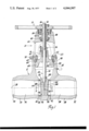
- FIG. 1 is a cross sectional view of a gate valve incorporating the present invention
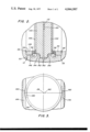
- FIG. 2 is an enlarged fragmentary cross sectional view taken along line 2--2 of FIG. 1 showing details of contruction of the present invention.
- FIG. 3 is a fragmentary axial cross sectional view showing the seat ring aligned with the notches in the guide rails.
- FIG. 1 there is shown a gate valve 10 in accordance with the present invention of the general type shown and described in the aforementioned Anders application Ser. No. 605,277 and reference may be made thereto for additional details of construction.
- the gate valve 10 comprises a valve body 12, a bonnet assembly 14, a yoke assembly 20 and a hand wheel assembly 22. Rotation of the hand wheel assembly 22 raises and lowers an internal stem assembly 24 and a double disc gate 26 to open and close a fluid passage extending through the valve body 12 along an axis 28 between a left hand outlet 30 and a right hand outlet 32.
- the valve body 12 is a generally T-shaped cast carbon steel construction and includes outlet sections 33 and 34 and a control section 35 mutually intersecting a valving chamber occupied by the gate 26.
- the section 33 includes the aforementioned outlet 30 and a flow passage 36.
- the section 34 includes the aforementioned outlet 32 and a flow passage 38.
- the passages 36 and 38 are coaxially disposed along the flow axis 28.
- the inner ends of the passages 36 and 38 are formed with counterbores 50 and 52 which receive tapered cylindrical seat rings 54.
- the seat rings 54 are provided with annular seats 56 formed in planes inclined with respect to an operational axis 42 perpendicularly intersecting the flow axis 28.
- the planes of the seats 56 are symmetrically disposed with respect to the axes 42, 48.
- the seat rings 54 are fixed to the inner surface of the valve body at continuous circumferential welds 58 (FIG. 2).
- the bonnet assembly 14 is retained at the upper end of the section 35 by means of the split retainer ring 60.
- Bolts 62 clamp the ring 60 to draw the outer flange 63 of the bonnet 64 upwardly against the retainer ring 60 which is retained in a peripheral circumferential channel section 65.
- the bonnet 64 is centrally apertured and receives the stem 70 of assembly 24.
- the hand wheel assembly 22 is attached to the upper end of the stem 70.
- the gate 26 is attached to the lower end of the stem 70 at enlarged T-slot connection 130, 148.
- a packing gland 76 seals the periphery of the stem 70.
- the yoke assembly 20 is retained at the top of section 35 by means of a split yoke lock ring 78.
- a pair of roller bearings 80, 82 have their outer races received in counterbores at the upper end of the yoke 20 and their inner races fixedly carried at opposite ends of a rotatable bushing 84 which has an internal thread engaging the threaded end 86 of the stem.
- the bushing 84 is keyed to the hand wheel such that the rotation of the latter rotates the bushing 84 to raise and lower the stem 70 through the packing gland 76. This in turn raises and lowers the gate 26 between the illustrated lowered closed position and a raised open position wherein the gate 26 is housed within a generally hemispherical depression 90 in the lower surface of the bonnet 64.
- the gate 26 comprises two identically formed gate discs 102 and 100, each of which has a hardened surface 104 engaging the hardened seats 56 of the seat rings 54.
- the surfaces 104 are similarly inclined with respect to the seats 56.
- the gate discs 100 and 102 are separated by spacer ring 120 and interlocking interiorly disposed hub.
- the individual discs 100 and 120 are provided with laterally projecting vertically extending tongues 140 which ride in the grooves 142 defined between pairs of inwardly projecting, vertically extending axially spaced guide rails 144, which pairs are laterally spaced on opposite sides of the axis 28.
- the inner guide surfaces of the guide rails 144 slidably engage the outer side surfaces of the tongues 140 to guide the gate 26 in its movement between positions.
- the seat rings 54 have outer cylindrical surface 146, an annular axial end face 147, an annular inclined seating face 148, and an inner cylindrical surface 149.
- the surface 146 has a larger diameter than the spacing laterally between the inner edges of the guide rails 144.
- the height in the horizontal plane of seat ring 54 as well as height in the lower half of the seat ring is greater than the axial spacing between the facing surfaces of the guide rails 144.
- crescent-shaped circular notches 160 are formed in the sides of the guide rails 144.
- the notches 160 have an axis coaxial with the flow axis 28 and the axis of the counterbores.
- the diameter of the notches 160 is slightly larger than the cylindrical surface 146 of the seat ring 54. Accordingly, with the seat ring 54 coaxially disposed within the notches 160, it is possible to axially shift the seat ring 54 into the associated counterbore.
- the grooves 142 can be made slightly wider than the height of the seat ring 54 as measured in the horizontal plane in which case the seat ring 54 may be directly lowered to a coaxial position with the notches 160 and axially shifted into seating relationship within the counterbores.
- a further savings in valve size and weight can be obtained by keeping the guide rails 144 as close together as possible, both laterally and axially, with the groove 142 being only slightly wider than the minor height of the seat ring 54 as measured in the cross section in the vertical plane.
- the groove 142 has a depth such that, when the ring is rotated 90° and inserted therewithin as shown by the dashed line 178 at the right hand side of FIG.
- the major height of the seat ring diametrically opposite therefrom and having a height greater than the groove width, as shown by the dashed lines 180 in FIG. 3, is located inwardly of the inner edge of the rails 144.
- the ring 54 may be vertically lowered into the valving chamber with the ring translating downwardly in the groove.
- the axis 182 of the seat ring 54 during this translation will be radially spaced to the right of the axis 28.
- the ring 54 is horizontally shifted into coaxial alignment with the axis 28.
- notched relief in combination with the relative dimensions between the height of the seat and the width of the groove, permits the guide rails 144 to be spaced considerably more compactly than would otherwise be the case, thereby resulting in a pressure vessel of reduced size and weight with a consequential cost savings. While this invention has been disclosed with reference to a tapered gate, it will be apparent that other gate constructions including parallel seating surfaces will accommodate the insertion of seat rings having outside diameters larger than the lateral spacing between the guide rails.
Landscapes
- Engineering & Computer Science (AREA)
- General Engineering & Computer Science (AREA)
- Mechanical Engineering (AREA)
- Sliding Valves (AREA)
- Lift Valve (AREA)
Priority Applications (11)
| Application Number | Priority Date | Filing Date | Title |
|---|---|---|---|
| US05/721,947 US4044997A (en) | 1976-09-10 | 1976-09-10 | Seat ring notch for gate valve guide rail |
| CA283,947A CA1057271A (en) | 1976-09-10 | 1977-08-03 | Seat ring notch for gate valve guide rail |
| AU27617/77A AU512896B2 (en) | 1976-09-10 | 1977-08-04 | Split-disc gate valve |
| GB32870/77A GB1582472A (en) | 1976-09-10 | 1977-08-05 | Gate valve |
| SE7710100A SE7710100L (sv) | 1976-09-10 | 1977-09-08 | Slussventil |
| NL7709932A NL7709932A (nl) | 1976-09-10 | 1977-09-09 | Zittingring inkeping voor een geleidingsrail van een schuifafsluiter. |
| ES462253A ES462253A1 (es) | 1976-09-10 | 1977-09-09 | Perfeccionamientos en valvulas de compuerta. |
| FR7727292A FR2364390A1 (fr) | 1976-09-10 | 1977-09-09 | Vanne perfectionnee a rails de guidage de l'obturateur |
| DE19772740782 DE2740782A1 (de) | 1976-09-10 | 1977-09-09 | Absperrschieber |
| JP10801477A JPS5334135A (en) | 1976-09-10 | 1977-09-09 | Gate valve |
| BR7705998A BR7705998A (pt) | 1976-09-10 | 1977-09-09 | Valvula de gaveta |
Applications Claiming Priority (1)
| Application Number | Priority Date | Filing Date | Title |
|---|---|---|---|
| US05/721,947 US4044997A (en) | 1976-09-10 | 1976-09-10 | Seat ring notch for gate valve guide rail |
Publications (1)
| Publication Number | Publication Date |
|---|---|
| US4044997A true US4044997A (en) | 1977-08-30 |
Family
ID=24899918
Family Applications (1)
| Application Number | Title | Priority Date | Filing Date |
|---|---|---|---|
| US05/721,947 Expired - Lifetime US4044997A (en) | 1976-09-10 | 1976-09-10 | Seat ring notch for gate valve guide rail |
Country Status (11)
| Country | Link |
|---|---|
| US (1) | US4044997A (sv) |
| JP (1) | JPS5334135A (sv) |
| AU (1) | AU512896B2 (sv) |
| BR (1) | BR7705998A (sv) |
| CA (1) | CA1057271A (sv) |
| DE (1) | DE2740782A1 (sv) |
| ES (1) | ES462253A1 (sv) |
| FR (1) | FR2364390A1 (sv) |
| GB (1) | GB1582472A (sv) |
| NL (1) | NL7709932A (sv) |
| SE (1) | SE7710100L (sv) |
Cited By (6)
| Publication number | Priority date | Publication date | Assignee | Title |
|---|---|---|---|---|
| US5211373A (en) * | 1990-11-14 | 1993-05-18 | Dwight Baker | Gate valve having expanding gate and floating seats |
| CN103717919A (zh) * | 2011-08-08 | 2014-04-09 | 费斯托股份有限两合公司 | 环状的锚固元件和以此装备的流体技术组件 |
| US8973897B2 (en) | 2012-01-03 | 2015-03-10 | Forum Us, Inc. | Valve seat retention pin |
| WO2016172347A1 (en) * | 2015-04-24 | 2016-10-27 | Flowserve Management Company | Parallel slide gate valves and related methods |
| WO2020132392A1 (en) * | 2018-12-21 | 2020-06-25 | Perimeter Solutions Lp | Gate valve sealing ring flow guide |
| EP3879153A4 (en) * | 2018-12-14 | 2022-08-24 | Kitz Corporation | GATE VALVE |
Families Citing this family (1)
| Publication number | Priority date | Publication date | Assignee | Title |
|---|---|---|---|---|
| NL182018C (nl) * | 1978-06-19 | 1987-12-16 | Midland Industries Ltd | Afsluiter. |
Citations (2)
| Publication number | Priority date | Publication date | Assignee | Title |
|---|---|---|---|---|
| US880463A (en) * | 1898-05-19 | 1908-02-25 | Pakin Company | Gate-valve. |
| US1765717A (en) * | 1927-04-23 | 1930-06-24 | Ericsson Gunnar | High-duty-valve structure |
Family Cites Families (3)
| Publication number | Priority date | Publication date | Assignee | Title |
|---|---|---|---|---|
| US2787439A (en) * | 1952-02-20 | 1957-04-02 | Crane Co | Valve construction |
| US3078871A (en) * | 1960-01-13 | 1963-02-26 | Crane Co | Gate closure guide |
| GB1543939A (en) * | 1975-08-18 | 1979-04-11 | Rockwell International Corp | Gate valve |
-
1976
- 1976-09-10 US US05/721,947 patent/US4044997A/en not_active Expired - Lifetime
-
1977
- 1977-08-03 CA CA283,947A patent/CA1057271A/en not_active Expired
- 1977-08-04 AU AU27617/77A patent/AU512896B2/en not_active Expired
- 1977-08-05 GB GB32870/77A patent/GB1582472A/en not_active Expired
- 1977-09-08 SE SE7710100A patent/SE7710100L/sv unknown
- 1977-09-09 ES ES462253A patent/ES462253A1/es not_active Expired
- 1977-09-09 FR FR7727292A patent/FR2364390A1/fr not_active Withdrawn
- 1977-09-09 NL NL7709932A patent/NL7709932A/xx not_active Application Discontinuation
- 1977-09-09 BR BR7705998A patent/BR7705998A/pt unknown
- 1977-09-09 JP JP10801477A patent/JPS5334135A/ja active Pending
- 1977-09-09 DE DE19772740782 patent/DE2740782A1/de not_active Withdrawn
Patent Citations (2)
| Publication number | Priority date | Publication date | Assignee | Title |
|---|---|---|---|---|
| US880463A (en) * | 1898-05-19 | 1908-02-25 | Pakin Company | Gate-valve. |
| US1765717A (en) * | 1927-04-23 | 1930-06-24 | Ericsson Gunnar | High-duty-valve structure |
Cited By (11)
| Publication number | Priority date | Publication date | Assignee | Title |
|---|---|---|---|---|
| US5211373A (en) * | 1990-11-14 | 1993-05-18 | Dwight Baker | Gate valve having expanding gate and floating seats |
| CN103717919A (zh) * | 2011-08-08 | 2014-04-09 | 费斯托股份有限两合公司 | 环状的锚固元件和以此装备的流体技术组件 |
| CN103717919B (zh) * | 2011-08-08 | 2016-10-19 | 费斯托股份有限两合公司 | 环状的锚固元件和以此装备的流体技术组件 |
| US8973897B2 (en) | 2012-01-03 | 2015-03-10 | Forum Us, Inc. | Valve seat retention pin |
| WO2016172347A1 (en) * | 2015-04-24 | 2016-10-27 | Flowserve Management Company | Parallel slide gate valves and related methods |
| US10100936B2 (en) | 2015-04-24 | 2018-10-16 | Flowserve Management Company | Parallel slide gate valves and related methods |
| EP3879153A4 (en) * | 2018-12-14 | 2022-08-24 | Kitz Corporation | GATE VALVE |
| US11486499B2 (en) * | 2018-12-14 | 2022-11-01 | Kitz Corporation | Gate valve |
| JP7361719B2 (ja) | 2018-12-14 | 2023-10-16 | 株式会社キッツ | 仕切弁 |
| WO2020132392A1 (en) * | 2018-12-21 | 2020-06-25 | Perimeter Solutions Lp | Gate valve sealing ring flow guide |
| US10962121B2 (en) | 2018-12-21 | 2021-03-30 | Perimeter Solutions Lp | Gate valve sealing ring flow guide |
Also Published As
| Publication number | Publication date |
|---|---|
| AU512896B2 (en) | 1980-11-06 |
| SE7710100L (sv) | 1978-03-11 |
| GB1582472A (en) | 1981-01-07 |
| NL7709932A (nl) | 1978-03-14 |
| DE2740782A1 (de) | 1978-03-16 |
| FR2364390A1 (fr) | 1978-04-07 |
| CA1057271A (en) | 1979-06-26 |
| AU2761777A (en) | 1979-02-08 |
| ES462253A1 (es) | 1978-05-16 |
| BR7705998A (pt) | 1978-06-20 |
| JPS5334135A (en) | 1978-03-30 |
Similar Documents
| Publication | Publication Date | Title |
|---|---|---|
| US4113268A (en) | Extended temperature range valve seal | |
| US4519412A (en) | Valve and seal therefor | |
| US3993285A (en) | Double disc gate valve with entrapped stem connection | |
| US3955591A (en) | Insert type sliding gate valve | |
| US4044997A (en) | Seat ring notch for gate valve guide rail | |
| US3742976A (en) | Valves | |
| US5908046A (en) | Back seat rising stem gate valve | |
| CA2969903A1 (en) | Valve body and seat with tongue and groove connection | |
| US3069129A (en) | Valve construction having fluid pressure and spring bias seals | |
| US2970805A (en) | Valves having resilient seals | |
| US4542878A (en) | Ball valve | |
| US4389037A (en) | Double disc gate vale with replaceable spacer ring | |
| GB1571875A (en) | Extendend temperature range valve seal | |
| US3814380A (en) | Adjustable body seat for butterfly valves | |
| US4077604A (en) | Cylindrical gate valve body | |
| US4320777A (en) | Actuator mechanism for lift-turn valves | |
| US4971098A (en) | Valve and improved seat seal therefor | |
| US3593960A (en) | Disc valve with upstream and downstream seats | |
| US4098489A (en) | Segmented hub for retaining the spacer ring of a two piece gate valve | |
| US4621790A (en) | Butterfly valve | |
| US3884268A (en) | Valve construction and method of making the same | |
| US4482128A (en) | High pressure cam seal valve | |
| CA1066259A (en) | Double disc gate valve with replaceable spacer ring | |
| US4081174A (en) | Gate valve | |
| US4376524A (en) | Low stress stem connection structure for a non-rising stem type gate valve |
Legal Events
| Date | Code | Title | Description |
|---|---|---|---|
| AS | Assignment |
Owner name: M&FC HOLDING COMPANY, INC., A DE. CORP. Free format text: ASSIGNMENT OF ASSIGNORS INTEREST.;ASSIGNOR:ROCKWELL INTERNATIONAL CORPORATION, A DE. CORP.;REEL/FRAME:005156/0851 Effective date: 19890310 |