US4044839A - Soil cultivating machines - Google Patents
Soil cultivating machines Download PDFInfo
- Publication number
- US4044839A US4044839A US05/613,903 US61390375A US4044839A US 4044839 A US4044839 A US 4044839A US 61390375 A US61390375 A US 61390375A US 4044839 A US4044839 A US 4044839A
- Authority
- US
- United States
- Prior art keywords
- shaft
- soil
- soil cultivating
- cultivating machine
- axis
- Prior art date
- Legal status (The legal status is an assumption and is not a legal conclusion. Google has not performed a legal analysis and makes no representation as to the accuracy of the status listed.)
- Expired - Lifetime
Links
Images

Classifications
-
- A—HUMAN NECESSITIES
- A01—AGRICULTURE; FORESTRY; ANIMAL HUSBANDRY; HUNTING; TRAPPING; FISHING
- A01B—SOIL WORKING IN AGRICULTURE OR FORESTRY; PARTS, DETAILS, OR ACCESSORIES OF AGRICULTURAL MACHINES OR IMPLEMENTS, IN GENERAL
- A01B33/00—Tilling implements with rotary driven tools, e.g. in combination with fertiliser distributors or seeders, with grubbing chains, with sloping axles, with driven discs
- A01B33/06—Tilling implements with rotary driven tools, e.g. in combination with fertiliser distributors or seeders, with grubbing chains, with sloping axles, with driven discs with tools on vertical or steeply-inclined shaft
- A01B33/065—Tilling implements with rotary driven tools, e.g. in combination with fertiliser distributors or seeders, with grubbing chains, with sloping axles, with driven discs with tools on vertical or steeply-inclined shaft comprising a plurality of rotors carried by an elongate, substantially closed transmission casing, transversely connectable to a tractor
Definitions
- a soil cultivating machine comprising at least one working member arranged to be rotatably driven about an upwardly extending axis and provided with at least one soil cultivating means arranged on the working member and adapted to rotate about an axis at an angle to the rotary axis of the working member.
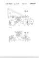
- FIG. 1 is a schematic plan view of a soil cultivating machine shown hitched to a tractor
- FIG. 2 is an enlarged elevational view taken in the direction of the arrow II in FIG. 1,
- FIG. 3 is an elevational view in the direction of the arrow III in FIG. 2,
- FIG. 4 is part of an elevational view in the direction of the arrow II in FIG. 1 but illustrating a second embodiment.
- the soil cultivating machine or implement shown in FIGS. 1 to 3 has a frame having two horizontal frame beams 1 spaced apart one behind the other and extending transversely of the intended direction of operative travel A of the machine.
- the frame beams 1 are parallel to one another and interconnected at equal distances from the center by means of tie beams 2 extending in the direction of travel A.
- the ends of the frame beams 1 are coupled with one another by means of strips 3, extending in the direction of travel A.
- Gear boxes 4 are carried by the outermost lateral faces of the tie beams 2.
- a substantially upright shaft 5 In each of the gear boxes 4 is journalled a substantially upright shaft 5, the longitudinal centre line a of which constitutes the rotary axis of a working member 6. From FIG. 2 it will be apparent that the gear boxes 4 are arranged so that the shafts 5 are slightly inclined to the front from bottom to top. Below the gear boxes 4 and the shafts 5 are held in sleeves 7 by means of two spaced ball bearings 8 lying one above the other.
- each shaft 5 carries a support 9 having four straight crosswise arranged arms 10 extending radially from the shaft 5 and tapering towards their outer ends. Viewed in a direction at right angles to the shaft 5, the arms 10 are slightly inclined downwards towards their free ends (see FIG. 4).
- the end of each arm 10 is provided with a stub shaft 11, the longitudinal center line b of which crosses substantially at right angles the longitudinal center line a of the corresponding shaft 5.
- the longitudinal center line b of each shaft 11 is at an angle to the longitudinal center line c of the corresponding arm 10 so that away from the fastening points on the respective arms the stub shafts 11 extend to the rear, viewed with respect to the intended direction of operative rotation of the working member (see FIG. 1).
- Each stub shaft 11 is provided by means of a ball bearing 12A with a soil cultivating means formed by a hollow disc 12.
- the hollow side of the disc 12 faces the shaft 5.
- the discs 12 have at their circumferences equally spaced recesses 13 and the portions 14 located between these recesses 13 have a cutting edge.
- each arms 15 can be set and fixed in any selected one of a plurality of positions by means of a bolt 16 passed through a hole in strip 3 and a selected one of a plurality of holes in a sector-shaped portion 17 of the arms 15.
- the free ends of the arms 15 have bearings 18 in which the ends of a substantially horizontal, rotatable working member 19, extending transversely of the direction of travel A, are freely rotatable.
- the working member 19 is provided at its circumference with elongated elements 20, extending in the direction of the rotary axis of the member 19.
- the elongated elements 20, preferably formed by circular-section bars, are supported from equally spaced plates 22, arranged on a central, tubular support 21.
- the foremost frame beam 1 is provided at the level of the tie beams 2 with forwardly converging supports 23 holding a trestle 24 with the aid of which the machine can be attached, as illustrated, to the three-point lifting device of a tractor.
- the top of the trestle 24 is connected with the rearmost frame beam 1 by means of supports 25 diverging rearwardly away from the trestle.
- Each shaft 5 is drivably connected in its gear box 4 by means of a bevel gear wheel 26 with a bevel gear wheel 27 on a shaft 28 which extends transversely of the direction of travel A and thus parallel to the frame beams 1.
- the shaft 28 is disposed in a tube 29 having a gear box 30 near its mid-point.
- the shaft 28 is drivably connected by means of a bevel gear wheel 31 with a bevel gear wheel 32 on a shaft 33, which projects from the front of the gear box 30 and extends substantially in the direction of travel A.
- the shaft 33 can be connected via an auxiliary shaft 34 and as illustrated with the power take-off shaft of the tractor.
- the discs Since with respect to the direction of rotation of the working members the discs are arranged so that their leading edge portions are farther remote from the rotary axis of their working member than their trailing edge portions, these discs exert a propelling effect on the machine during their rearward movement so that the tractive force required for moving the machine is reduced. Since the shafts 5 are slightly inclined forwardly in the direction of travel A, the discs 12 when near the front of the working members are, in operation, at a greater depth in the soil than when near the rear. In this way the lower layer of the strip of soil cultivated is crumbled up more coarsely than the upper layer.
- the machine can be extremely useful on fields still having remains of crop or much weed, since the discs not only cut up these remains but also cover the so cut-up remains.
- the inclined position of the discs with respect to the path described by them ensures an effective drive of the discs and, in addition, an effective turning-up of the soil, while the discs have a propelling effect on the machine.
- the ends of the arms 10 of the working members are provided with groups of tines 35 forming the soil cultivating means.
- the groups of tines 35 are adapted to rotate about an upright shaft 36, which is at an acute angle to the rotary shaft of the corresponding working member 6, viewed at right angles to the working member rotary axis a.
- the top end of the shaft 36 of each group of tines 35 is further remote from the rotary axis a of the corresponding working member than the lower end.
- Each shaft 36 is rotatably supported by means of two ball bearings 37 spaced apart in overlying position in a sleeve 38 fastened to the end of a corresponding arm 10 and at the lower end the shaft 36 carries a support 39 having three arms 40.
- the arms 40 extend radially of the shaft 36 and are at circumferential angles of about 120° to one another. Viewed in a direction at right angles to the shaft 36, the arms 40 are slightly inclined downwards from the shaft towards their free ends. At its outer end each arm 40 is provided with a holder 41 receiving a fastening portion 42 of a tine 35, which portion terminates in a downwardly extending operative portion 43.
- the operative portion 43 is substantially straight and tapers inwardly towards its free end. From FIG. 4 it will be seen that the operative portions 43 of the respective tines 35 are substantially parallel to their rotary shaft 36.
- the longitudinal center line of each tine fastening portion 42 is at an angle of preferably 8° to the longitudinal center line of the operative portion 43.
- the working members 6 of this embodiment are driven about the vertical shafts 5 and during their rotation, which corresponds with that of the working members 6 of the first embodiment, the groups of tines 35 are driven in clockwise direction so that they work overlapping strips of soil. Since the rotary shafts 36 of the soil cultivating means formed by the groups of tines 35, freely rotating viewed in a direction at right angles to the rotary axis a of each working member 6, are at an angle to this rotary axis a so that the top end of such shaft 36 is further remote from the rotary axis a than the lower end, the free ends of the tines 35 are passed across the soil along the paths inclined to the horizontal.
- the rotary movement of the group of tines is such that the tines can readily dig up weeds and roots from the subsoil, which is extremely important on fields strongly contaminated by weeds such as grasses.
- the strip of soil worked by the working members 6 of both emobdiments described is subsequently treated by the elongated elements 20 of the rotatable working member 19 so that the worked soil is engaged and distributed so that a most advantageous seed bed is obtained.
- the working member 19 can be set and fixed in any selected one of a plurality of positions so that this working member can be used to adjust the effective depth of the soil cultivating means of the respective working members 6.
Landscapes
- Life Sciences & Earth Sciences (AREA)
- Engineering & Computer Science (AREA)
- Mechanical Engineering (AREA)
- Soil Sciences (AREA)
- Environmental Sciences (AREA)
- Soil Working Implements (AREA)
Applications Claiming Priority (2)
| Application Number | Priority Date | Filing Date | Title |
|---|---|---|---|
| NL7412331A NL7412331A (nl) | 1974-09-18 | 1974-09-18 | Grondbewerkingsmachine. |
| NL7412331 | 1974-09-18 |
Publications (1)
| Publication Number | Publication Date |
|---|---|
| US4044839A true US4044839A (en) | 1977-08-30 |
Family
ID=19822120
Family Applications (1)
| Application Number | Title | Priority Date | Filing Date |
|---|---|---|---|
| US05/613,903 Expired - Lifetime US4044839A (en) | 1974-09-18 | 1975-09-16 | Soil cultivating machines |
Country Status (6)
| Country | Link |
|---|---|
| US (1) | US4044839A (enExample) |
| DE (1) | DE2541287A1 (enExample) |
| FR (1) | FR2285057A1 (enExample) |
| GB (1) | GB1523905A (enExample) |
| IT (1) | IT1042674B (enExample) |
| NL (1) | NL7412331A (enExample) |
Cited By (16)
| Publication number | Priority date | Publication date | Assignee | Title |
|---|---|---|---|---|
| US4109731A (en) * | 1975-07-24 | 1978-08-29 | Lely Cornelis V D | Soil cultivating implements |
| US4113025A (en) * | 1975-08-25 | 1978-09-12 | Lely Cornelis V D | Soil cultivating implements |
| US4224999A (en) * | 1977-03-02 | 1980-09-30 | Lely Cornelis V D | Soil cultivating implements |
| US4287955A (en) * | 1979-06-07 | 1981-09-08 | Anderson Jack F | Rotary tiller device |
| US4491183A (en) * | 1981-03-03 | 1985-01-01 | Jack F. Anderson | Retractable in-row tiller device |
| US4936390A (en) * | 1986-12-05 | 1990-06-26 | Town & Country Research & Development, Inc. | Tool apparatus with tool attached to end of outrigger arm |
| US5287932A (en) * | 1990-11-29 | 1994-02-22 | Maschinenfabrik Bermatingen Gmbh & Co. | Soil tilling device |
| WO1996015655A1 (en) * | 1994-11-24 | 1996-05-30 | Ro-Tree Corporation Australia Pty. Limited | Cultivator |
| US6662880B2 (en) * | 2000-06-09 | 2003-12-16 | Gedalyahu Manor | Traveling rolling digger for sequential hole drilling and for producing sequential cultivated spots in soil |
| US6763895B1 (en) * | 1999-09-06 | 2004-07-20 | Wilkinsons Pty Ltd | Cultivating apparatus |
| US20070074645A1 (en) * | 2005-09-30 | 2007-04-05 | Turfco Manufacturing, Inc. | Turf overseeding apparatus and methods |
| US20080008542A1 (en) * | 2003-08-06 | 2008-01-10 | Roger Arnold Stromsoe | Impact Compactor |
| CN103782677A (zh) * | 2014-02-17 | 2014-05-14 | 衢州市煜鑫农产品加工技术开发有限公司 | 一种牵引式松土机具 |
| US9943021B2 (en) * | 2016-08-24 | 2018-04-17 | Blake Berbereia | Row digger |
| US10212871B2 (en) * | 2016-08-24 | 2019-02-26 | Blake Berbereia | Row digger |
| RU2686621C1 (ru) * | 2018-10-15 | 2019-04-29 | Виктор Михайлович Островерх | Культиватор редукционно-роторный секционный с комплектом вращающихся внутрипочвенных лопастей "ВИКОСТ" |
Citations (11)
| Publication number | Priority date | Publication date | Assignee | Title |
|---|---|---|---|---|
| DE69803C (de) * | A.BERG in Raversbeuren, Post Irmenach, R.-B. Coblenz | Acker- und Wiesenegge | ||
| US75310A (en) * | 1868-03-10 | Improvement in steam-plough and cultivator | ||
| US534638A (en) * | 1895-02-26 | Harrow attachment for wheel-cu ltivators | ||
| US661307A (en) * | 1899-12-21 | 1900-11-06 | Thomas C Darby | Implement for cultivating land. |
| US1113241A (en) * | 1910-08-11 | 1914-10-13 | Frank B Niesz | Double disk harrow. |
| US2429298A (en) * | 1945-10-08 | 1947-10-21 | John O Savage | Pulverizing disc plow |
| US2619017A (en) * | 1947-01-20 | 1952-11-25 | Orley R Stephenson | Rotary disk plow |
| GB847413A (en) * | 1957-01-08 | 1960-09-07 | Natale Porta | A tillage implement |
| US3130794A (en) * | 1961-07-05 | 1964-04-28 | Ford D Lovell | Earth shaping implement |
| US3199607A (en) * | 1964-01-13 | 1965-08-10 | Emil J Granius | Attachment for garden tractor |
| US3899030A (en) * | 1970-12-18 | 1975-08-12 | Der Lely Ary Van | Soil compressing members |
-
1974
- 1974-09-18 NL NL7412331A patent/NL7412331A/xx active Search and Examination
-
1975
- 1975-09-15 GB GB37896/75A patent/GB1523905A/en not_active Expired
- 1975-09-16 DE DE19752541287 patent/DE2541287A1/de not_active Withdrawn
- 1975-09-16 FR FR7528300A patent/FR2285057A1/fr active Granted
- 1975-09-16 US US05/613,903 patent/US4044839A/en not_active Expired - Lifetime
- 1975-09-18 IT IT27392/75A patent/IT1042674B/it active
Patent Citations (11)
| Publication number | Priority date | Publication date | Assignee | Title |
|---|---|---|---|---|
| DE69803C (de) * | A.BERG in Raversbeuren, Post Irmenach, R.-B. Coblenz | Acker- und Wiesenegge | ||
| US75310A (en) * | 1868-03-10 | Improvement in steam-plough and cultivator | ||
| US534638A (en) * | 1895-02-26 | Harrow attachment for wheel-cu ltivators | ||
| US661307A (en) * | 1899-12-21 | 1900-11-06 | Thomas C Darby | Implement for cultivating land. |
| US1113241A (en) * | 1910-08-11 | 1914-10-13 | Frank B Niesz | Double disk harrow. |
| US2429298A (en) * | 1945-10-08 | 1947-10-21 | John O Savage | Pulverizing disc plow |
| US2619017A (en) * | 1947-01-20 | 1952-11-25 | Orley R Stephenson | Rotary disk plow |
| GB847413A (en) * | 1957-01-08 | 1960-09-07 | Natale Porta | A tillage implement |
| US3130794A (en) * | 1961-07-05 | 1964-04-28 | Ford D Lovell | Earth shaping implement |
| US3199607A (en) * | 1964-01-13 | 1965-08-10 | Emil J Granius | Attachment for garden tractor |
| US3899030A (en) * | 1970-12-18 | 1975-08-12 | Der Lely Ary Van | Soil compressing members |
Cited By (19)
| Publication number | Priority date | Publication date | Assignee | Title |
|---|---|---|---|---|
| US4109731A (en) * | 1975-07-24 | 1978-08-29 | Lely Cornelis V D | Soil cultivating implements |
| US4113025A (en) * | 1975-08-25 | 1978-09-12 | Lely Cornelis V D | Soil cultivating implements |
| US4224999A (en) * | 1977-03-02 | 1980-09-30 | Lely Cornelis V D | Soil cultivating implements |
| US4287955A (en) * | 1979-06-07 | 1981-09-08 | Anderson Jack F | Rotary tiller device |
| US4491183A (en) * | 1981-03-03 | 1985-01-01 | Jack F. Anderson | Retractable in-row tiller device |
| US4936390A (en) * | 1986-12-05 | 1990-06-26 | Town & Country Research & Development, Inc. | Tool apparatus with tool attached to end of outrigger arm |
| US5287932A (en) * | 1990-11-29 | 1994-02-22 | Maschinenfabrik Bermatingen Gmbh & Co. | Soil tilling device |
| US5944115A (en) * | 1994-11-24 | 1999-08-31 | Padgett; Kenneth John | Cultivator |
| WO1996015655A1 (en) * | 1994-11-24 | 1996-05-30 | Ro-Tree Corporation Australia Pty. Limited | Cultivator |
| US6763895B1 (en) * | 1999-09-06 | 2004-07-20 | Wilkinsons Pty Ltd | Cultivating apparatus |
| US6662880B2 (en) * | 2000-06-09 | 2003-12-16 | Gedalyahu Manor | Traveling rolling digger for sequential hole drilling and for producing sequential cultivated spots in soil |
| US20080008542A1 (en) * | 2003-08-06 | 2008-01-10 | Roger Arnold Stromsoe | Impact Compactor |
| US7614821B2 (en) * | 2003-08-06 | 2009-11-10 | Impact Compaction (Proprietary) Limited | Impact compactor |
| US20070074645A1 (en) * | 2005-09-30 | 2007-04-05 | Turfco Manufacturing, Inc. | Turf overseeding apparatus and methods |
| US7448333B2 (en) | 2005-09-30 | 2008-11-11 | Turfco Manufacturing, Inc. | Turf overseeding apparatus and methods |
| CN103782677A (zh) * | 2014-02-17 | 2014-05-14 | 衢州市煜鑫农产品加工技术开发有限公司 | 一种牵引式松土机具 |
| US9943021B2 (en) * | 2016-08-24 | 2018-04-17 | Blake Berbereia | Row digger |
| US10212871B2 (en) * | 2016-08-24 | 2019-02-26 | Blake Berbereia | Row digger |
| RU2686621C1 (ru) * | 2018-10-15 | 2019-04-29 | Виктор Михайлович Островерх | Культиватор редукционно-роторный секционный с комплектом вращающихся внутрипочвенных лопастей "ВИКОСТ" |
Also Published As
| Publication number | Publication date |
|---|---|
| IT1042674B (it) | 1980-01-30 |
| NL7412331A (nl) | 1976-03-22 |
| FR2285057B1 (enExample) | 1982-01-29 |
| FR2285057A1 (fr) | 1976-04-16 |
| DE2541287A1 (de) | 1976-04-08 |
| GB1523905A (en) | 1978-09-06 |
Similar Documents
| Publication | Publication Date | Title |
|---|---|---|
| US3945441A (en) | Soil cultivating implements | |
| US4537262A (en) | Soil cultivation | |
| US3821989A (en) | Rotary harrows | |
| US4267891A (en) | Soil cultivating machines | |
| US4051903A (en) | Soil cultivating machines | |
| US4148363A (en) | Soil cultivating implements | |
| US4071089A (en) | Soil cultivating implements | |
| GB2142513A (en) | Soil cultivating implements | |
| US4641713A (en) | Soil cultivating machines | |
| GB1587289A (en) | Soil cultivating implements | |
| US4077477A (en) | Soil cultivating implements | |
| US4090571A (en) | Soil cultivating implements | |
| US4088196A (en) | Soil cultivating implements | |
| US4050519A (en) | Soil cultivating machines | |
| GB1595126A (en) | Soil cultivating implements | |
| US4884640A (en) | Soil cultivating implements | |
| GB2127262A (en) | A soil cultivating machine | |
| US4042042A (en) | Soil cultivating machines | |
| GB2130862A (en) | Soil cultivating implements | |
| US4063596A (en) | Soil cultivating machines | |
| US4060134A (en) | Soil cultivating implements | |
| GB2090712A (en) | Soil cultivating equipment | |
| GB1594286A (en) | Soil cultivating implements | |
| GB2151443A (en) | Soil cultivating implements | |
| US4127177A (en) | Soil cultivating implements |