US4040203A - Rotating core rods - Google Patents
Rotating core rods Download PDFInfo
- Publication number
- US4040203A US4040203A US05/684,668 US68466876A US4040203A US 4040203 A US4040203 A US 4040203A US 68466876 A US68466876 A US 68466876A US 4040203 A US4040203 A US 4040203A
- Authority
- US
- United States
- Prior art keywords
- core rods
- gear
- rotate
- chamber
- core
- Prior art date
- Legal status (The legal status is an assumption and is not a legal conclusion. Google has not performed a legal analysis and makes no representation as to the accuracy of the status listed.)
- Expired - Lifetime
Links
Images

Classifications
-
- B—PERFORMING OPERATIONS; TRANSPORTING
- B29—WORKING OF PLASTICS; WORKING OF SUBSTANCES IN A PLASTIC STATE IN GENERAL
- B29C—SHAPING OR JOINING OF PLASTICS; SHAPING OF MATERIAL IN A PLASTIC STATE, NOT OTHERWISE PROVIDED FOR; AFTER-TREATMENT OF THE SHAPED PRODUCTS, e.g. REPAIRING
- B29C49/00—Blow-moulding, i.e. blowing a preform or parison to a desired shape within a mould; Apparatus therefor
- B29C49/42—Component parts, details or accessories; Auxiliary operations
- B29C49/64—Heating or cooling preforms, parisons or blown articles
- B29C49/6409—Thermal conditioning of preforms
- B29C49/6418—Heating of preforms
-
- B—PERFORMING OPERATIONS; TRANSPORTING
- B29—WORKING OF PLASTICS; WORKING OF SUBSTANCES IN A PLASTIC STATE IN GENERAL
- B29C—SHAPING OR JOINING OF PLASTICS; SHAPING OF MATERIAL IN A PLASTIC STATE, NOT OTHERWISE PROVIDED FOR; AFTER-TREATMENT OF THE SHAPED PRODUCTS, e.g. REPAIRING
- B29C49/00—Blow-moulding, i.e. blowing a preform or parison to a desired shape within a mould; Apparatus therefor
- B29C49/42—Component parts, details or accessories; Auxiliary operations
- B29C49/4236—Drive means
-
- B—PERFORMING OPERATIONS; TRANSPORTING
- B29—WORKING OF PLASTICS; WORKING OF SUBSTANCES IN A PLASTIC STATE IN GENERAL
- B29C—SHAPING OR JOINING OF PLASTICS; SHAPING OF MATERIAL IN A PLASTIC STATE, NOT OTHERWISE PROVIDED FOR; AFTER-TREATMENT OF THE SHAPED PRODUCTS, e.g. REPAIRING
- B29C2949/00—Indexing scheme relating to blow-moulding
- B29C2949/07—Preforms or parisons characterised by their configuration
- B29C2949/0715—Preforms or parisons characterised by their configuration the preform having one end closed
-
- B—PERFORMING OPERATIONS; TRANSPORTING
- B29—WORKING OF PLASTICS; WORKING OF SUBSTANCES IN A PLASTIC STATE IN GENERAL
- B29C—SHAPING OR JOINING OF PLASTICS; SHAPING OF MATERIAL IN A PLASTIC STATE, NOT OTHERWISE PROVIDED FOR; AFTER-TREATMENT OF THE SHAPED PRODUCTS, e.g. REPAIRING
- B29C49/00—Blow-moulding, i.e. blowing a preform or parison to a desired shape within a mould; Apparatus therefor
- B29C49/02—Combined blow-moulding and manufacture of the preform or the parison
- B29C49/06—Injection blow-moulding
Definitions
- This invention relates to temperature conditioning a plurality of parisons. Specifically, this invention relates to rotating a plurality of core rods with parisons thereon in a temperature conditioned chamber to effect even temperature distribution throughout the parisons.
- Such prior art devices required the separate handling and conditioning of each parison, and further required the parison to be removed from the machine on which it was formed and placed in such devices for heating and then subsequent mounted on a blow molding apparatus.
- an apparatus which permits simultaneous rotation of a plurality of parisons mounted on their respective core rods to effect even temperature distribution with the core rods positioned in a temperature conditioning chamber.
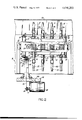
- FIG. 1 is a partial sectional elevational view of the apparatus of the invention with three pluralities of core rods in the temperature conditioning chambers, at an operation station, and a fourth plurality of core rods being depicted at the changeover station; and
- FIG. 2 is a sectional view taken along line 2--2 of FIG. 1.
- the apparatus of the invention is generally designated as 10.
- Core rods 11a-11d having injection molded parisons 12 thereon are rotatably mounted in bushings 13 to each side of square block 14.
- Block 14 in turn is vertically rotatably mounted about its horizontally disposed axis 15, to indexing head 16 which is horizontally rotatable.
- Head 16 is mounted to a spline shaft (not shown) and is rotatably indexed at a plurality of injection blow molding stations, in the well known manner.
- one plurality of core rods 11a is horizontally outwardly disposed, whereas each of the other pluralities of core rods namely 11b, 11c and 11d are disposed in temperature conditioning chambers 17b, 17c and 17d, respectively.
- the core rods at a horizontally outwardly disposed station may be undergoing one of several operations such as injection molding, blow molding or stripping (not shown) all in the well known manner.
- the core rods in chambers 17b, 17c and 17d undergo temperature conditioning to effect even temperature distribution of the parisons prior to blow molding so that the parisons are assuredly at the desired blow molding temperature. This is particularly so in orientation blow molding wherein the parisons must be conditioned within the molecular orientation temperature range.
- the core rods are cycled at the changeover station 17a, as block 14 being supportably rotatably mounted on bearings 22, undergoes rotation by the action of apparatus 20 engaging block pin 21 (typical), and with an upward vertical drive of 20 effects this rotation.
- this core rod cycling apparatus at the changeover station is the subject matter of another, copending application.
- each core rod moves successively from a 17a position to 17b to 17c to 17d and back to a 17a position with the parison fully temperature conditioned for blow molding, as shown in copending commonly-owned application, U.S. Ser. No. 635,898, filed Nov. 28, 1975, now U.S. Pat. No. 3,985,485, granted Oct. 17, 1976.
- the pluralities of core rods 11a and 11b of stations 17b and 17d undergo simultaneous rotation whereas the pluralities of core rods 17a and 17c do not rotate, as will be more fully explained hereinafter.
- Each core rod 11a-11d is mounted within a sprocket 25, and is affixedly held to core rod by mounting members 26, so that the sprocket 25 and core rod will rotate together in bushing 13.
- Members 26 reside in recess 27 of each core rod.
- the bushing 13 is mounted in housing 28 which in turn is mounted to block 14.
- a first gear assembly 29 is mounted through block 14 so that shaft 30 is parallel to the axes of core rods 11b and 11d
- a second gear assembly 31 is mounted through block 14 so that its shaft 32 is parallel to the axes of core rods 11a and 11c.
- the axes of shafts 30 and 32 are perpendicularly disposed and in accurate spaced relationship for purposes hereinafter appearing.
- Gear assembly 29 comprises shaft 30 mounted in bushings 30a and 30b and bevel gears 35 and 36, are mounted on the opposite ends of shaft 30.
- Sprockets 37 and 38 are concentrically mounted and fixedly held to respective bevel gears 35 and 36.
- Sprockets 37 and 38 engage chains 40 and 41 respectively which chains engage the sprockets of core rods 11b and 11d, respectively in an over and under manner so that adjacent core rods rotate simultaneously but in opposite directions.
- Support sprockets 42 and 43 are rotatably mounted on shaft 44 which transverses block 14 so that shafts 44 and 30 are in parallel disposition.
- Chain 40 engages sprocket 42 whereas chain 41 engages sprocket 43.
- Gear assembly 31 is similar in construction to gear assembly 29.
- a drive motor 50 is mounted by flange 50a to frame 54.
- Said motor 50 is provided with shaft 51, and drive sprocket 52 mounted thereon.
- An endless chain 53 engages drive sprocket 52 and also engages sprocket 60.
- Sprocket 60 is part of gear assembly 55 which is supportably mounted by flange portions 56 and 57, which flange portions are in turn mounted to frame 54.
- Gear assembly 55 comprises a double bevel gear 58 and 59 disposed on opposite sides of sprocket 60 and bevel gears 58, 59 as well as sprocket 60 are mounted in bearings 61 and 62 of flange portion 56 and 57, respectively.
- motor 50 drives shaft 51 and sprocket 52 to in turn drive chain 53 which in turn causes rotation of sprocket 60 and bevel gears 58 and 59.
- bevel gear 58 enmeshes with bevel gear 36 so as to cause rotation of shaft 30.
- sprocket 37 is rotated driving chain 40, sprocket 42, and rotating core rods 11b simultaneously with core rods 11d.
- Bevel gear 36 engages bevel gear 58 when the core rods are indexed, and in the next indexing cycle with block rotation then at the changeover station 17a, as depicted by arrow A, bevel gear 70 of shaft 32 will engage bevel gear 59 so that core rods 11a and 11c will then undergo rotations in a manner similar to that of core rods 11b and 11d heretofore described.
- the distances between bevel gears 58 and 59, and shafts 30 and 32, are accurately provided for, to effect this alternate drive from the single drive source 50.
- core rods 11b and 11d undergo rotation in temperature conditioning chambers 17b and 17d, respectively, whereas core rods 11a and 11c are not rotated.
- core rods 11a may be undergoing an injection blow molding operation (not shown) as aforesaid, and therefore must be non-rotating.
- Temperature conditioning chambers 17b, 17c and 17d are housed within plenum 80 which extends around the entire periphery of the turntable. Internal members 81a, 81b, 81c and 81d provide support for the chamber construction. Each chamber 17b, 17c and 17d is provided with inlet and outlet ports 82a, 82b, 83a, 83b; and 84a, 84b. Referring specifically to 82a and 82b, although similar construction is provided for the other temperature conditioning chambers, inlet port 82a opens through the top wall 80a of plenum 80.
- Fluid for temperature control is supplied to port 82a from fluid temperature control means 148 which has a temperature control adjustment 150, and a blower 152 for forcing air through the fluid temperature control means 148 and through inlet port 82a.
- fluid temperature control means 148 which has a temperature control adjustment 150, and a blower 152 for forcing air through the fluid temperature control means 148 and through inlet port 82a.
- Separate fluid temperature means can be provided for each inlet port, so that the temperature can be different in different chambers and at different locations around the plenum.
- the outlet port 82a is shown connected with an exhaust blower 160.
- the blowers 152 and 150 are preferably drive by motors 164 having speed controllers 166 for regulating the rate of flow of the temperature control fluid to and from the chambers.
- a drive assembly comprising basically, the drive motor assembly, drive chain, and double bevel gear assembly, may be provided at each indexing station around the periphery of the indexing head, so that there is some rotation of the vertically disposed core rods at each station, except of course the changeover station.
Landscapes
- Engineering & Computer Science (AREA)
- Manufacturing & Machinery (AREA)
- Mechanical Engineering (AREA)
- Physics & Mathematics (AREA)
- Thermal Sciences (AREA)
- Blow-Moulding Or Thermoforming Of Plastics Or The Like (AREA)
- Processing And Handling Of Plastics And Other Materials For Molding In General (AREA)
Abstract
Description
Claims (10)
Priority Applications (1)
| Application Number | Priority Date | Filing Date | Title |
|---|---|---|---|
| US05/684,668 US4040203A (en) | 1976-05-10 | 1976-05-10 | Rotating core rods |
Applications Claiming Priority (1)
| Application Number | Priority Date | Filing Date | Title |
|---|---|---|---|
| US05/684,668 US4040203A (en) | 1976-05-10 | 1976-05-10 | Rotating core rods |
Publications (1)
| Publication Number | Publication Date |
|---|---|
| US4040203A true US4040203A (en) | 1977-08-09 |
Family
ID=24749049
Family Applications (1)
| Application Number | Title | Priority Date | Filing Date |
|---|---|---|---|
| US05/684,668 Expired - Lifetime US4040203A (en) | 1976-05-10 | 1976-05-10 | Rotating core rods |
Country Status (1)
| Country | Link |
|---|---|
| US (1) | US4040203A (en) |
Citations (4)
| Publication number | Priority date | Publication date | Assignee | Title |
|---|---|---|---|---|
| US3840999A (en) * | 1973-05-16 | 1974-10-15 | Sun Chemical Corp | Apparatus for radiation-curing of coating on multi-sided object |
| US3883295A (en) * | 1972-10-16 | 1975-05-13 | Armco Steel Corp | Rotary hearth furnace |
| US3930788A (en) * | 1974-05-24 | 1976-01-06 | Beloit Corporation | Parison oven |
| US3935647A (en) * | 1974-07-16 | 1976-02-03 | Continental Can Company, Inc. | Ultraviolet curing oven |
-
1976
- 1976-05-10 US US05/684,668 patent/US4040203A/en not_active Expired - Lifetime
Patent Citations (4)
| Publication number | Priority date | Publication date | Assignee | Title |
|---|---|---|---|---|
| US3883295A (en) * | 1972-10-16 | 1975-05-13 | Armco Steel Corp | Rotary hearth furnace |
| US3840999A (en) * | 1973-05-16 | 1974-10-15 | Sun Chemical Corp | Apparatus for radiation-curing of coating on multi-sided object |
| US3930788A (en) * | 1974-05-24 | 1976-01-06 | Beloit Corporation | Parison oven |
| US3935647A (en) * | 1974-07-16 | 1976-02-03 | Continental Can Company, Inc. | Ultraviolet curing oven |
Similar Documents
| Publication | Publication Date | Title |
|---|---|---|
| US4224263A (en) | Method for blow molding | |
| CN205980667U (en) | Belt transport formula hair products microwave drying device | |
| US4234297A (en) | Apparatus for blow molding | |
| US3935647A (en) | Ultraviolet curing oven | |
| CN113787671B (en) | Plastic housing injection molding equipment for processing electric vehicle controller | |
| CN209358838U (en) | A louver vertical flap cooler for circuit board processing | |
| CN115503272B (en) | Production device of rubber tire | |
| CN210850775U (en) | A ceramic rolling drying production line | |
| JP4097319B2 (en) | Method and apparatus for automatic setting of drawing rod position | |
| US1985697A (en) | Drying machine | |
| JPH0645940U (en) | Carry-in machine | |
| CN221217862U (en) | Uniform blowing device of tempering furnace | |
| US6338623B1 (en) | Rotational molding oven | |
| US4180379A (en) | Blow molding machine with rotating core rods | |
| TWM585777U (en) | Oven with swaying type conveyor device | |
| CN214842306U (en) | A vertical plate dryer | |
| CN223973337U (en) | Stoving heat preservation conveyer | |
| CN221657059U (en) | Online heating and curing device for vehicle wheel after paint spraying | |
| CN222715247U (en) | Glass bottle annealing cooling device | |
| CN212764719U (en) | Bottleneck positioning device of numerical control plastic bottle blowing machine | |
| CN215524112U (en) | A lithium battery cell oven | |
| CN221744639U (en) | Hot air drying device for workpiece | |
| CN221505513U (en) | A drying device for biscuit production | |
| US2748537A (en) | Vertical annealing lehr | |
| CN222313210U (en) | Heat treatment cooling device for screw production |
Legal Events
| Date | Code | Title | Description |
|---|---|---|---|
| AS | Assignment |
Owner name: WEDCO TECHNOLOGY, INC., P.O. BOX 397, BLOOMSBURY, Free format text: ASSIGNMENT OF ASSIGNORS INTEREST.;ASSIGNOR:FARRELL PATENT COMPANY;REEL/FRAME:004852/0403 Effective date: 19880329 Owner name: WEDCO TECHNOLOGY, INC., NEW JERSEY Free format text: ASSIGNMENT OF ASSIGNORS INTEREST;ASSIGNOR:FARRELL PATENT COMPANY;REEL/FRAME:004852/0403 Effective date: 19880329 |
|
| AS | Assignment |
Owner name: WEDCO TECHNOLOGY, INC., P.O. BOX 397, BLOOMSBURY, Free format text: ASSIGNMENT OF ASSIGNORS INTEREST.;ASSIGNOR:FARRELL PATENT COMPANY;REEL/FRAME:005036/0828 Effective date: 19881123 |
|
| AS | Assignment |
Owner name: TDT, INC., 208 COUGAR COURT, A CORP. OF NJ., NEW J Free format text: ASSIGNMENT OF ASSIGNORS INTEREST.;ASSIGNOR:WEDCO TECHNOLOGY, INC., P.O. BOX 397, BLOOMSBURY, NJ., ACORP. OF NJ.;REEL/FRAME:005237/0072 Effective date: 19890424 |
|
| AS | Assignment |
Owner name: BM, INC., A CORP. OF NJ Free format text: ASSIGNMENT OF ASSIGNORS INTEREST.;ASSIGNOR:TDT, INC., A CORP. OF NJ;REEL/FRAME:005113/0035 Effective date: 19760203 |