US4035461A - Method of making an extravertable-wall container - Google Patents
Method of making an extravertable-wall container Download PDFInfo
- Publication number
- US4035461A US4035461A US05/549,000 US54900075A US4035461A US 4035461 A US4035461 A US 4035461A US 54900075 A US54900075 A US 54900075A US 4035461 A US4035461 A US 4035461A
- Authority
- US
- United States
- Prior art keywords
- container
- cup
- cavity
- mandrel
- cup portion
- Prior art date
- Legal status (The legal status is an assumption and is not a legal conclusion. Google has not performed a legal analysis and makes no representation as to the accuracy of the status listed.)
- Expired - Lifetime
Links
Images


Classifications
-
- B—PERFORMING OPERATIONS; TRANSPORTING
- B65—CONVEYING; PACKING; STORING; HANDLING THIN OR FILAMENTARY MATERIAL
- B65D—CONTAINERS FOR STORAGE OR TRANSPORT OF ARTICLES OR MATERIALS, e.g. BAGS, BARRELS, BOTTLES, BOXES, CANS, CARTONS, CRATES, DRUMS, JARS, TANKS, HOPPERS, FORWARDING CONTAINERS; ACCESSORIES, CLOSURES, OR FITTINGS THEREFOR; PACKAGING ELEMENTS; PACKAGES
- B65D21/00—Nestable, stackable or joinable containers; Containers of variable capacity
- B65D21/02—Containers specially shaped, or provided with fittings or attachments, to facilitate nesting, stacking, or joining together
- B65D21/0233—Nestable containers
-
- B—PERFORMING OPERATIONS; TRANSPORTING
- B29—WORKING OF PLASTICS; WORKING OF SUBSTANCES IN A PLASTIC STATE IN GENERAL
- B29C—SHAPING OR JOINING OF PLASTICS; SHAPING OF MATERIAL IN A PLASTIC STATE, NOT OTHERWISE PROVIDED FOR; AFTER-TREATMENT OF THE SHAPED PRODUCTS, e.g. REPAIRING
- B29C49/00—Blow-moulding, i.e. blowing a preform or parison to a desired shape within a mould; Apparatus therefor
- B29C49/0031—Making articles having hollow walls
-
- B—PERFORMING OPERATIONS; TRANSPORTING
- B29—WORKING OF PLASTICS; WORKING OF SUBSTANCES IN A PLASTIC STATE IN GENERAL
- B29C—SHAPING OR JOINING OF PLASTICS; SHAPING OF MATERIAL IN A PLASTIC STATE, NOT OTHERWISE PROVIDED FOR; AFTER-TREATMENT OF THE SHAPED PRODUCTS, e.g. REPAIRING
- B29C49/00—Blow-moulding, i.e. blowing a preform or parison to a desired shape within a mould; Apparatus therefor
- B29C49/02—Combined blow-moulding and manufacture of the preform or the parison
- B29C49/06—Injection blow-moulding
-
- B—PERFORMING OPERATIONS; TRANSPORTING
- B29—WORKING OF PLASTICS; WORKING OF SUBSTANCES IN A PLASTIC STATE IN GENERAL
- B29C—SHAPING OR JOINING OF PLASTICS; SHAPING OF MATERIAL IN A PLASTIC STATE, NOT OTHERWISE PROVIDED FOR; AFTER-TREATMENT OF THE SHAPED PRODUCTS, e.g. REPAIRING
- B29C49/00—Blow-moulding, i.e. blowing a preform or parison to a desired shape within a mould; Apparatus therefor
- B29C49/42—Component parts, details or accessories; Auxiliary operations
- B29C49/48—Moulds
- B29C49/54—Moulds for undercut articles
- B29C49/541—Moulds for undercut articles having a recessed undersurface
-
- B—PERFORMING OPERATIONS; TRANSPORTING
- B29—WORKING OF PLASTICS; WORKING OF SUBSTANCES IN A PLASTIC STATE IN GENERAL
- B29C—SHAPING OR JOINING OF PLASTICS; SHAPING OF MATERIAL IN A PLASTIC STATE, NOT OTHERWISE PROVIDED FOR; AFTER-TREATMENT OF THE SHAPED PRODUCTS, e.g. REPAIRING
- B29C67/00—Shaping techniques not covered by groups B29C39/00 - B29C65/00, B29C70/00 or B29C73/00
-
- B—PERFORMING OPERATIONS; TRANSPORTING
- B29—WORKING OF PLASTICS; WORKING OF SUBSTANCES IN A PLASTIC STATE IN GENERAL
- B29C—SHAPING OR JOINING OF PLASTICS; SHAPING OF MATERIAL IN A PLASTIC STATE, NOT OTHERWISE PROVIDED FOR; AFTER-TREATMENT OF THE SHAPED PRODUCTS, e.g. REPAIRING
- B29C69/00—Combinations of shaping techniques not provided for in a single one of main groups B29C39/00 - B29C67/00, e.g. associations of moulding and joining techniques; Apparatus therefore
- B29C69/02—Combinations of shaping techniques not provided for in a single one of main groups B29C39/00 - B29C67/00, e.g. associations of moulding and joining techniques; Apparatus therefore of moulding techniques only
- B29C69/025—Deforming articles in a simpler intermediate shape without internal stresses for packaging transporting or storage and reshaping and fixing the original configuration on the place of use
-
- B—PERFORMING OPERATIONS; TRANSPORTING
- B65—CONVEYING; PACKING; STORING; HANDLING THIN OR FILAMENTARY MATERIAL
- B65D—CONTAINERS FOR STORAGE OR TRANSPORT OF ARTICLES OR MATERIALS, e.g. BAGS, BARRELS, BOTTLES, BOXES, CANS, CARTONS, CRATES, DRUMS, JARS, TANKS, HOPPERS, FORWARDING CONTAINERS; ACCESSORIES, CLOSURES, OR FITTINGS THEREFOR; PACKAGING ELEMENTS; PACKAGES
- B65D1/00—Containers having bodies formed in one piece, e.g. by casting metallic material, by moulding plastics, by blowing vitreous material, by throwing ceramic material, by moulding pulped fibrous material, by deep-drawing operations performed on sheet material
- B65D1/02—Bottles or similar containers with necks or like restricted apertures, designed for pouring contents
- B65D1/0223—Bottles or similar containers with necks or like restricted apertures, designed for pouring contents characterised by shape
- B65D1/0292—Foldable bottles
-
- B—PERFORMING OPERATIONS; TRANSPORTING
- B65—CONVEYING; PACKING; STORING; HANDLING THIN OR FILAMENTARY MATERIAL
- B65D—CONTAINERS FOR STORAGE OR TRANSPORT OF ARTICLES OR MATERIALS, e.g. BAGS, BARRELS, BOTTLES, BOXES, CANS, CARTONS, CRATES, DRUMS, JARS, TANKS, HOPPERS, FORWARDING CONTAINERS; ACCESSORIES, CLOSURES, OR FITTINGS THEREFOR; PACKAGING ELEMENTS; PACKAGES
- B65D1/00—Containers having bodies formed in one piece, e.g. by casting metallic material, by moulding plastics, by blowing vitreous material, by throwing ceramic material, by moulding pulped fibrous material, by deep-drawing operations performed on sheet material
- B65D1/22—Boxes or like containers with side walls of substantial depth for enclosing contents
- B65D1/26—Thin-walled containers, e.g. formed by deep-drawing operations
- B65D1/265—Drinking cups
-
- B—PERFORMING OPERATIONS; TRANSPORTING
- B29—WORKING OF PLASTICS; WORKING OF SUBSTANCES IN A PLASTIC STATE IN GENERAL
- B29C—SHAPING OR JOINING OF PLASTICS; SHAPING OF MATERIAL IN A PLASTIC STATE, NOT OTHERWISE PROVIDED FOR; AFTER-TREATMENT OF THE SHAPED PRODUCTS, e.g. REPAIRING
- B29C49/00—Blow-moulding, i.e. blowing a preform or parison to a desired shape within a mould; Apparatus therefor
- B29C49/02—Combined blow-moulding and manufacture of the preform or the parison
- B29C2049/023—Combined blow-moulding and manufacture of the preform or the parison using inherent heat of the preform, i.e. 1 step blow moulding
-
- B—PERFORMING OPERATIONS; TRANSPORTING
- B29—WORKING OF PLASTICS; WORKING OF SUBSTANCES IN A PLASTIC STATE IN GENERAL
- B29C—SHAPING OR JOINING OF PLASTICS; SHAPING OF MATERIAL IN A PLASTIC STATE, NOT OTHERWISE PROVIDED FOR; AFTER-TREATMENT OF THE SHAPED PRODUCTS, e.g. REPAIRING
- B29C49/00—Blow-moulding, i.e. blowing a preform or parison to a desired shape within a mould; Apparatus therefor
- B29C49/42—Component parts, details or accessories; Auxiliary operations
- B29C49/48—Moulds
- B29C2049/4856—Mounting, exchanging or centering moulds or parts thereof
- B29C2049/4858—Exchanging mould parts, e.g. for changing the mould size or geometry for making different products in the same mould
-
- B—PERFORMING OPERATIONS; TRANSPORTING
- B29—WORKING OF PLASTICS; WORKING OF SUBSTANCES IN A PLASTIC STATE IN GENERAL
- B29C—SHAPING OR JOINING OF PLASTICS; SHAPING OF MATERIAL IN A PLASTIC STATE, NOT OTHERWISE PROVIDED FOR; AFTER-TREATMENT OF THE SHAPED PRODUCTS, e.g. REPAIRING
- B29C49/00—Blow-moulding, i.e. blowing a preform or parison to a desired shape within a mould; Apparatus therefor
- B29C49/42—Component parts, details or accessories; Auxiliary operations
- B29C49/48—Moulds
- B29C49/54—Moulds for undercut articles
- B29C2049/542—Moulds for undercut articles having means to facilitate the removal of the blow moulded articles
- B29C2049/548—Moulds for undercut articles having means to facilitate the removal of the blow moulded articles the movement of the mould parts during opening of the mould are interlinked
-
- B—PERFORMING OPERATIONS; TRANSPORTING
- B29—WORKING OF PLASTICS; WORKING OF SUBSTANCES IN A PLASTIC STATE IN GENERAL
- B29C—SHAPING OR JOINING OF PLASTICS; SHAPING OF MATERIAL IN A PLASTIC STATE, NOT OTHERWISE PROVIDED FOR; AFTER-TREATMENT OF THE SHAPED PRODUCTS, e.g. REPAIRING
- B29C49/00—Blow-moulding, i.e. blowing a preform or parison to a desired shape within a mould; Apparatus therefor
- B29C49/02—Combined blow-moulding and manufacture of the preform or the parison
- B29C49/04—Extrusion blow-moulding
-
- B—PERFORMING OPERATIONS; TRANSPORTING
- B29—WORKING OF PLASTICS; WORKING OF SUBSTANCES IN A PLASTIC STATE IN GENERAL
- B29C—SHAPING OR JOINING OF PLASTICS; SHAPING OF MATERIAL IN A PLASTIC STATE, NOT OTHERWISE PROVIDED FOR; AFTER-TREATMENT OF THE SHAPED PRODUCTS, e.g. REPAIRING
- B29C49/00—Blow-moulding, i.e. blowing a preform or parison to a desired shape within a mould; Apparatus therefor
- B29C49/02—Combined blow-moulding and manufacture of the preform or the parison
- B29C49/06—Injection blow-moulding
- B29C49/0665—Injection blow-moulding the injection mould cavity and the blow-mould cavity being displaceable to the geometrically fixed injection core mould
-
- B—PERFORMING OPERATIONS; TRANSPORTING
- B29—WORKING OF PLASTICS; WORKING OF SUBSTANCES IN A PLASTIC STATE IN GENERAL
- B29C—SHAPING OR JOINING OF PLASTICS; SHAPING OF MATERIAL IN A PLASTIC STATE, NOT OTHERWISE PROVIDED FOR; AFTER-TREATMENT OF THE SHAPED PRODUCTS, e.g. REPAIRING
- B29C49/00—Blow-moulding, i.e. blowing a preform or parison to a desired shape within a mould; Apparatus therefor
- B29C49/42—Component parts, details or accessories; Auxiliary operations
- B29C49/4273—Auxiliary operations after the blow-moulding operation not otherwise provided for
- B29C49/4283—Deforming the finished article
Definitions
- the present invention relates to a method of making a container structure which is versatile, stackable and compact.
- containers with thin thermoplastic walls from thermoplastic synthetic resins such as polyethylene and vinyl polymers have found increasing acceptance in recent years.
- Such containers may be made by a blow-molding process in which a hollow thermoplastic parison is injected or extruded into a cavity which is expanded to form a blow mold. Fluid is introduced into the interior of the parison while the latter is still in a plastically deformable state to expand the parison into contact with the walls of the mold, thereby producing a receptacle of small wall thickness and complex or simple design as may be desired.
- Another object is to provide a method of making an improved low-cost multiple-use receptacle or container, e.g. bottle, of thermoplastic synthetic resin which can be conveniently handled, manufactured, filled and stored.
- containers of this type are fabricated from thermoplastic synthetic resin by injection molding a parison into a cavity, engaging a part of the parison (e.g. a portion corresponding to the neck of the vessel to be made), and blowing the parison after withdrawal of the walls of the original cavity, to conform to a blow mold cavity, whereupon one end of the blow molded container is pressed into the other end of the latter so that the pressed-in part can be expanded outwardly again for the extraverting action mentioned previously.
- a part of the parison e.g. a portion corresponding to the neck of the vessel to be made
- the collapse is effected while part of the parison (e.g. the neck) remains fixed in a gripper portion of the mold structure so that this part is not blown, expanded or reduced in thickness.
- part of the parison e.g. the neck
- the apparatus for producing the container according to the invention comprises a blow-molding and injection-molding apparatus, the injection-molding apparatus including a blowing mandrel and a mold-forming head which cooperates with this mandrel to define the mold cavity for the preform or parison.
- Means is provided for injecting through this latter member the thermoplastic synthetic resin material and for withdrawing this nozzle from the blow mold cavity to permit expansion of the parison into contact with the walls thereof.
- An essential feature of this aspect of the invention resides in providing this nozzle as the means for inwardly collapsing the collapsible half of the container or as part of the collapsing tool.
- the injection-molding and collapsing tool is thus movably disposed in the blow-mold cavity and cooperates with a mandrel which cooperates with transversely movable slide members to form the neck of the container.
- the collapsing tool can be withdrawn through an opening in the blow-mold cavity and this opening can be closed by slidable shutters designed to form the bottom of the blow-mold cavity.
- this collapsing member has been found to be advantageous to shape this collapsing member with an elongated cup-shaped recess in the direction of the blowing mandrel and advantageously widening in this direction the recess or cavity extending from the end of the injection-nozzle orifice which thus terminates within the collapsing member.
- the time required for pressing one half of the container into the other half is short and hence does not interfere with the production capacity of the apparatus. Since the container resembles a cup in the collapsed condition, it can be stacked with similar shaped bodies in further small space so that the volume required for each collapsed container is a further small fraction of the volume of the filled noncollapsed container.
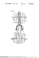
- FIG. 1 is a longitudinal section in diagrammatic form through an apparatus for carrying out the method in accordance with the present invention and showing a first stage thereof;
- FIG. 2 is a view similar to FIG. 1 illustrating the position of the parts after blowing of the parison;
- FIG. 3 is a view similar to FIGS. 1 and 2 showing the apparatus in the position following blowing in which the lower half of the container is collapsed into the upper half thereof;
- FIG. 4a shows a stack of the collapsed containers according to the present invention, the upper one in section and the lower containers in elevation;
- An injection-molding nozzle 8 can be introduced into the blow mold cavity 3 axially through the bore 1a' in the lower mold half 1a and has a cup-shaped recess 10a in its end open toward the blowing mandrel 7 which has a slight outward taper conforming to the inward taper of the blowing mandrel 7.
- the injection-molding nozzle passage 9 terminates at an orifica 9a at the base of the cavity 10a so that thermoplastic synthetic resin can be injected into the space 15 defined between the mandrel 7 and the wall of recess 10a to form a closed-end tubular parison 2 with a neck 2a.
- blow mold opening 4 at the upper end of the cavity is closed by slides 11a and 11b except for the space 1b" and the blowing mandrel 7 which also forms a core about which the parison 2, 2a is formed.
- the passage 9 is connected with an injection-molding head of any conventional design and which produces a plastically flowable heated synthetic resin which is driven through the passage 9 into the mold cavity 15 formed between the nozzle body 8 and the mandrel 7 as described.
- a vertically elongated container 17 having a frustoconical cup-shaped lower half 17a which is geometrically similar to but smaller than the upper frustoconical cup-shaped half 17b.
- the neck 2a of the bottle is not blown and hence remains with its original thickness.
- the upper mold half 1b is withdrawn relative to the mandrel 7 after the slides 11a and 11b have disengaged the neck and nozzle body 8 is moved upwardly (also in FIG. 3) to carry the bottom of the container 17 upwardly and into the top of the container, i.e. to introvert the lower cup half 17a into the upper cup half 17b whereby the the annular shoulder 17c of the container lies at the upper lip of the double-wall cup thus formed.
- Compressed air is supplied through the passage 9 to depress the bottom of the inner cup wall upwardly by the pressure.
- a sleeve 12 which engages the neck 2a and is slidable on the injection and blowing mandrel 7. This sleeve 12 moves downwardly during the vertical rise of member 10 to reduce the total axial displacement necessary to achieve introversion of the lower cup half 17a.
- the container is then cut off at the neck 2a and has the configuration shown in FIG. 4a so that it can be stacked with smaller containers as there shown.
- the inner half 17a is extraverted gradually so that the filling liquid, e.g. milk, does not significantly foam.
- the container has the configuration shown in FIG. 4b.
- the neck 2a may be cut off or omitted in formation so that the structure will have the configuration shown in FIG. 5, namely, a double-wall drinking cup 22 with high heat-insulating properties.
- the two halves 22a and 22b are collapsed one into the other leaving a small airgap 23 between them.
Landscapes
- Engineering & Computer Science (AREA)
- Mechanical Engineering (AREA)
- Manufacturing & Machinery (AREA)
- Ceramic Engineering (AREA)
- Blow-Moulding Or Thermoforming Of Plastics Or The Like (AREA)
- Moulds For Moulding Plastics Or The Like (AREA)
Abstract
An extravertable-wall container is formed by extruding a parison into a blow-mold cavity having a pair of oppositely diverging halves which are joined at their widest portions, one half being slightly smaller than the other so that the frusto-conical wall of the container formed in this half can be pushed (compressed) into the other half to produce a stackable cup-shaped structure. When the container is to be filled, the inner wall portion is extraverted to form an extension of the container, e.g. the bottom. The container may have a frustoconical upwardly widening base which is geometrically smaller but inverted with respect to the larger frustoconical head. A neck or filling opening may be provided on this head.
Description
The present invention relates to a method of making a container structure which is versatile, stackable and compact.
The fabrication of containers with thin thermoplastic walls from thermoplastic synthetic resins such as polyethylene and vinyl polymers has found increasing acceptance in recent years. Such containers may be made by a blow-molding process in which a hollow thermoplastic parison is injected or extruded into a cavity which is expanded to form a blow mold. Fluid is introduced into the interior of the parison while the latter is still in a plastically deformable state to expand the parison into contact with the walls of the mold, thereby producing a receptacle of small wall thickness and complex or simple design as may be desired.
A problem with such containers is that they occupy as much space in an empty state as in filled condition and hence create difficulties with respect to transport and storage in the empty condition between manufacture and filling.
It has been proposed to shape these containers so that they can be stacked, but the same problem is nevertheless present since stacking depends on the head and bottom shapes of the vessels only and does not permit large numbers of them to occupy a substantially smaller volume than is occupied by the same number individually. In other words, the neck of the container may have a configuration complementary to a recess in the bottom so that either the empty or the filled containers can be stacked, but this does not permit a reduction of the storage volume for empty containers to any significant extent.
It is an object of the invention to provide a method of making an improved stackable container structure which can be conveniently transported and stored and nevertheless has a high capacity.
Another object is to provide a method of making an improved low-cost multiple-use receptacle or container, e.g. bottle, of thermoplastic synthetic resin which can be conveniently handled, manufactured, filled and stored.
Still another object of this invention is to provide a method of fabricating at low cost and in a serial manner containers of improved versatility, free from the disadvantages of earlier containers and fabrication methods.
These objects and others which will become apparent hereinafter are attained, in accordance with the present invention, by the provision of a blow-molded elongated container having geometrically similar but oppositely oriented upper and lower portions designed such that, after the container is blown, the smaller portion can be pressed into the larger portion so as to have the walls of the two portions lie in close juxtaposition and substantially parallel to one another. As a result, the container can be compacted into a cup-shaped body which can be stacked with similar cup-shaped bodies. For filling, the inner wall of the cup-shaped body is extraverted (rolled outwardly) to expand the container to its full height.
According to the principles of the present invention, containers of this type are fabricated from thermoplastic synthetic resin by injection molding a parison into a cavity, engaging a part of the parison (e.g. a portion corresponding to the neck of the vessel to be made), and blowing the parison after withdrawal of the walls of the original cavity, to conform to a blow mold cavity, whereupon one end of the blow molded container is pressed into the other end of the latter so that the pressed-in part can be expanded outwardly again for the extraverting action mentioned previously.
According to the principles of this invention, a substantial part, preferably about half, of the hollow body formed by blow molding is collapsed inwardly into the other half, to lie wholly within the other half with the walls of the two halves substantially parallel.
Preferably, the collapse is effected while part of the parison (e.g. the neck) remains fixed in a gripper portion of the mold structure so that this part is not blown, expanded or reduced in thickness.
According to another aspect of the invention, the apparatus for producing the container according to the invention comprises a blow-molding and injection-molding apparatus, the injection-molding apparatus including a blowing mandrel and a mold-forming head which cooperates with this mandrel to define the mold cavity for the preform or parison. Means is provided for injecting through this latter member the thermoplastic synthetic resin material and for withdrawing this nozzle from the blow mold cavity to permit expansion of the parison into contact with the walls thereof. An essential feature of this aspect of the invention resides in providing this nozzle as the means for inwardly collapsing the collapsible half of the container or as part of the collapsing tool.
The injection-molding and collapsing tool is thus movably disposed in the blow-mold cavity and cooperates with a mandrel which cooperates with transversely movable slide members to form the neck of the container. Similarly, the collapsing tool can be withdrawn through an opening in the blow-mold cavity and this opening can be closed by slidable shutters designed to form the bottom of the blow-mold cavity.
It has been found to be advantageous to shape this collapsing member with an elongated cup-shaped recess in the direction of the blowing mandrel and advantageously widening in this direction the recess or cavity extending from the end of the injection-nozzle orifice which thus terminates within the collapsing member.
According to still another feature of the invention, the upper and lower halves of the unitary, integral and one-piece container have the configuration of geometrically similar frustoconical cones adjoining at a shoulder at their widest portions.
In practice, it has been found that the time required for pressing one half of the container into the other half (collapsing the hollow body) is short and hence does not interfere with the production capacity of the apparatus. Since the container resembles a cup in the collapsed condition, it can be stacked with similar shaped bodies in further small space so that the volume required for each collapsed container is a further small fraction of the volume of the filled noncollapsed container.
Because of the manner in which the containers are collapsed and the way in which the inner part is extraverted during filling, the filling operation is greatly simplified and there is considerable advantage when the container is used for liquids like milk which tend to foam when cascaded into a large empty space. In the collapsed condition, there is only a small air volume between the portions or parts of the bottle, and the volume between these parts increases progressively with filling so that complex measures for discharging air from the bottle are superfluous. Foaming is precluded by the absence of free space.
Another advantage is that, in the collapsed condition, the structure forms a cup of double-wall design in which hot or cold liquids can be served with a minimum change in temperature since the air gap between the inner and outer halves is an excellent thermal insulation. Without the neck, therefore, the cup-shaped structure is a convenient liquid receptacle for drink-vending machines and the like.
Another advantage resides in the fact that after the filled container has been emptied the container can again be collapsed, e.g. by hand, to a compact structure for disposal or even for use as a drinking cup.
The above and other objects, features and advantages of the present invention will become more readily apparent from the following description, reference being made to the accompanying drawing inw which:
FIG. 1 is a longitudinal section in diagrammatic form through an apparatus for carrying out the method in accordance with the present invention and showing a first stage thereof;
FIG. 2 is a view similar to FIG. 1 illustrating the position of the parts after blowing of the parison;
FIG. 3 is a view similar to FIGS. 1 and 2 showing the apparatus in the position following blowing in which the lower half of the container is collapsed into the upper half thereof;
FIG. 4a shows a stack of the collapsed containers according to the present invention, the upper one in section and the lower containers in elevation;
FIG. 4b is a vertical elevational view of the filled container according to the invention; and
FIG. 5 is a cross section through a cup-shaped hollow body according to this invention.
In FIG. 1 I have shown an apparatus for the production of milk containers or other vessels adapted to be filled with a liquid and composed of thermoplastic synthetic resin.
The apparatus basically consists of a bipartite blow mold, 1a, 1b defining a mold cavity 3a and 3b having the general configuration of the container to be produced (see FIG. 4b).
At the upper end of the upper mold half 1b, the latter is provided with a pair of sliders 11a and 11b movable transversely to the axis of the device as presented by the arrows and defining with a wall 1b' , an annular space 1b" surrounding a blowing mandrel 7 which is axially shiftable from the position shown in FIG. 1 upwardly in the direction of the arrow. The compartment 1b" conforms to the neck of the bottle.
An injection-molding nozzle 8 can be introduced into the blow mold cavity 3 axially through the bore 1a' in the lower mold half 1a and has a cup-shaped recess 10a in its end open toward the blowing mandrel 7 which has a slight outward taper conforming to the inward taper of the blowing mandrel 7. The injection-molding nozzle passage 9 terminates at an orifica 9a at the base of the cavity 10a so that thermoplastic synthetic resin can be injected into the space 15 defined between the mandrel 7 and the wall of recess 10a to form a closed-end tubular parison 2 with a neck 2a.
The blow-mold cavity 3 is formed by the two frustoconical cavities 3a and 3b, the latter being geometrically similar but larger than the former. The wide bases of these frustoconical cavities adjoin at a shoulder 6. The frustocones differ only slightly in size.
The blow mold opening 4 at the upper end of the cavity is closed by slides 11a and 11b except for the space 1b" and the blowing mandrel 7 which also forms a core about which the parison 2, 2a is formed.
The passage 9 is connected with an injection-molding head of any conventional design and which produces a plastically flowable heated synthetic resin which is driven through the passage 9 into the mold cavity 15 formed between the nozzle body 8 and the mandrel 7 as described.
The end of the upper section 10 of the nozzle body 8 sealingly engages the slides 11a and 11b, closing the cavity 15. The region around the orifice 9a forms the bottom 16 of this cavity.
Once the synthetic-resin material has been injected to form the parison 2, 2a, the nozzle body 8 is withdrawn axially downwardly in the direction of the arrow shown in FIG. 2 and a pair of gates 20a, 20b are shifted laterally inwardly to define the bottom wall 20 of the blow-mold cavity. Compressed air is forced through the blowing mandrel 7 which is formed with an axial passage 18 terminating at an orifice 18' within the parison 2, 2a, the compressed air spreading inwardly (arrow 19) to force the synthetic resin against the walls of the mold 3.
As a result, there is formed a vertically elongated container 17 having a frustoconical cup-shaped lower half 17a which is geometrically similar to but smaller than the upper frustoconical cup-shaped half 17b. The neck 2a of the bottle is not blown and hence remains with its original thickness.
As can be seen from FIG. 3, in the next step the upper mold half 1b is withdrawn relative to the mandrel 7 after the slides 11a and 11b have disengaged the neck and nozzle body 8 is moved upwardly (also in FIG. 3) to carry the bottom of the container 17 upwardly and into the top of the container, i.e. to introvert the lower cup half 17a into the upper cup half 17b whereby the the annular shoulder 17c of the container lies at the upper lip of the double-wall cup thus formed. Compressed air is supplied through the passage 9 to depress the bottom of the inner cup wall upwardly by the pressure.
Within the container is a sleeve 12, which engages the neck 2a and is slidable on the injection and blowing mandrel 7. This sleeve 12 moves downwardly during the vertical rise of member 10 to reduce the total axial displacement necessary to achieve introversion of the lower cup half 17a. The container is then cut off at the neck 2a and has the configuration shown in FIG. 4a so that it can be stacked with smaller containers as there shown. When the container is filled, the inner half 17a is extraverted gradually so that the filling liquid, e.g. milk, does not significantly foam. In its filled state, the container has the configuration shown in FIG. 4b.
If desired, the neck 2a may be cut off or omitted in formation so that the structure will have the configuration shown in FIG. 5, namely, a double-wall drinking cup 22 with high heat-insulating properties. The two halves 22a and 22b are collapsed one into the other leaving a small airgap 23 between them.
Claims (3)
1. A method of making a container comprising the steps of:
enclosing a blowing mandrel in a blow mold having a first half surrounding said mandrel at a location spaced from an end thereof and defining a cup-shaped cavity widening away from said location, said mold having a second half formed with a cup-shaped cavity geometrically similar to the cup-shaped cavity of said first half and widening in the direction thereof, said cup-shaped cavities adjoining to produce a molding cavity having the configuration of a container to be formed;
advancing an injection nozzle through said second half to surround said mandrel and define an elongated injection cavity therewith;
injecting a thermoplastic synthetic-resin material into said injection cavity through said nozzle to form a closed end parison around said mandrel;
withdrawing said nozzle from said molding cavity through a wall of said second half and closing said wall;
blowing said parison through said mandrel to expand said parison against the walls of said molding cavity, thereby forming a container conforming to the configuration of said molding cavity and having a first cup portion lying in the cup-shaped cavity of said first half and a second cup portion lying in the cup-shaped cavity of said second half;
separating said first and second halves of said mold to release said container from said molding cavity; and
axially displacing said first cup portion toward said nozzle and advancing said nozzle toward said mandrel to entrain the bottom of said second cup portion into said first cup portion and introvert said second cup portion within said first cup portion.
2. The method defined in claim 1, further comprising the steps of molding a neck on said parison around said mandrel during the injection of said thermoplastic synthetic-resin material into said injection cavity.
3. The method defined in claim 1, further comprising the step of introducing a liquid filling material into said container to displace outwardly the introverted second cup portion during filling of the container.
Priority Applications (7)
| Application Number | Priority Date | Filing Date | Title |
|---|---|---|---|
| DE2341400A DE2341400C3 (en) | 1973-08-16 | 1973-08-16 | Method and device for producing a hollow body preferably filled with a liquid medium |
| IT26339/74A IT1019968B (en) | 1973-08-16 | 1974-08-14 | PROCEDURE AND DEVICE FOR THE REALIZATION OF HOLLOW BODIES OF THERMOPLASTIC MATERIAL AS PURE HOLLOW BODIES MADE ACCORDING TO THIS PROCEDURE |
| FR7442999A FR2295826A1 (en) | 1973-08-16 | 1974-12-27 | PROCESS AND DEVICE FOR THE MANUFACTURING OF HOLLOW BODIES FROM THERMOPLASTIC MATERIAL AND HOLLOW BODIES OBTAINED BY THIS PROCESS |
| BE152072A BE824020A (en) | 1973-08-16 | 1974-12-31 | METHOD AND DEVICE FOR THE MANUFACTURING OF HOLLOW BODIES FROM THERMOPLASTIC SYNTHETIC MATERIAL AS WELL AS HOLLOW BODIES MANUFACTURED BY THIS PROCESS |
| NL7500146A NL7500146A (en) | 1973-08-16 | 1975-01-07 | METHOD AND EQUIPMENT FOR THE MANUFACTURE OF HOLLOW BODIES OF THERMOPLASTIC MATERIAL, AS WELL AS HOLLOW BODIES MANUFACTURED BY THIS METHOD. |
| GB134175A GB1456171A (en) | 1973-08-16 | 1975-01-13 | Hollow bodies and method and apparatus for the production of hollow bodies |
| US05/549,000 US4035461A (en) | 1973-08-16 | 1975-02-11 | Method of making an extravertable-wall container |
Applications Claiming Priority (6)
| Application Number | Priority Date | Filing Date | Title |
|---|---|---|---|
| DE2341400A DE2341400C3 (en) | 1973-08-16 | 1973-08-16 | Method and device for producing a hollow body preferably filled with a liquid medium |
| FR7442999A FR2295826A1 (en) | 1973-08-16 | 1974-12-27 | PROCESS AND DEVICE FOR THE MANUFACTURING OF HOLLOW BODIES FROM THERMOPLASTIC MATERIAL AND HOLLOW BODIES OBTAINED BY THIS PROCESS |
| BE152072A BE824020A (en) | 1973-08-16 | 1974-12-31 | METHOD AND DEVICE FOR THE MANUFACTURING OF HOLLOW BODIES FROM THERMOPLASTIC SYNTHETIC MATERIAL AS WELL AS HOLLOW BODIES MANUFACTURED BY THIS PROCESS |
| NL7500146A NL7500146A (en) | 1973-08-16 | 1975-01-07 | METHOD AND EQUIPMENT FOR THE MANUFACTURE OF HOLLOW BODIES OF THERMOPLASTIC MATERIAL, AS WELL AS HOLLOW BODIES MANUFACTURED BY THIS METHOD. |
| GB134175A GB1456171A (en) | 1973-08-16 | 1975-01-13 | Hollow bodies and method and apparatus for the production of hollow bodies |
| US05/549,000 US4035461A (en) | 1973-08-16 | 1975-02-11 | Method of making an extravertable-wall container |
Publications (1)
| Publication Number | Publication Date |
|---|---|
| US4035461A true US4035461A (en) | 1977-07-12 |
Family
ID=32854580
Family Applications (1)
| Application Number | Title | Priority Date | Filing Date |
|---|---|---|---|
| US05/549,000 Expired - Lifetime US4035461A (en) | 1973-08-16 | 1975-02-11 | Method of making an extravertable-wall container |
Country Status (7)
| Country | Link |
|---|---|
| US (1) | US4035461A (en) |
| BE (1) | BE824020A (en) |
| DE (1) | DE2341400C3 (en) |
| FR (1) | FR2295826A1 (en) |
| GB (1) | GB1456171A (en) |
| IT (1) | IT1019968B (en) |
| NL (1) | NL7500146A (en) |
Cited By (39)
| Publication number | Priority date | Publication date | Assignee | Title |
|---|---|---|---|---|
| US4769206A (en) * | 1985-12-05 | 1988-09-06 | Krupp Corpoplast Maschienebau Gmbh | Method for producing a hollow body provided with a stand ring by blow moulding |
| US4770839A (en) * | 1986-05-28 | 1988-09-13 | John D. Brush & Co., Inc. | Reverse parison draping for blow molding |
| US4795652A (en) * | 1986-12-15 | 1989-01-03 | Cooper Concepts, Inc. | Method for forming an edible food container |
| US4805290A (en) * | 1986-02-10 | 1989-02-21 | John D. Brush & Co., Inc. | Blow molding of double-walled box in diagonal halves |
| US4828786A (en) * | 1986-05-28 | 1989-05-09 | John D. Brush & Co., Inc. | Draped parison blow molding |
| US4846662A (en) * | 1986-05-28 | 1989-07-11 | John D. Brush & Co., Inc. | Reverse parison draping for blow molding |
| US4948357A (en) * | 1986-05-28 | 1990-08-14 | John D. Brush & Co., Inc. | Draped parison blow molding apparatus |
| US5063094A (en) * | 1986-05-28 | 1991-11-05 | John D. Brush & Co., Inc. | Draped parison blow molded box |
| US5292242A (en) * | 1990-08-31 | 1994-03-08 | Robbins Edward S Iii | Apparatus for forming a collapsible container |
| WO1999033636A1 (en) * | 1997-12-23 | 1999-07-08 | Coraltech Limited | Thermoforming or blow moulding of injection moulded preforms |
| EP1044792A2 (en) * | 1999-03-31 | 2000-10-18 | Georg Emil Scheller | Method and apparatus for compressing of single-use cans |
| US6171539B1 (en) * | 1998-07-15 | 2001-01-09 | Sumitomo Wiring Systems, Ltd. | Method for forming a molded grommet |
| US20050139573A1 (en) * | 2003-12-30 | 2005-06-30 | Mitsuo Higuchi | Longitudinally expandable plastic bottle, and method and apparatus for manufacturing the same |
| US20050206044A1 (en) * | 2004-03-22 | 2005-09-22 | Mitsuo Higuchi | Manufacturing method for pet bottle capable of keeping state of being contracted in lengthwise direction |
| US20050230883A1 (en) * | 2004-04-14 | 2005-10-20 | Mitsuo Higuchi | Longitudinally expandable plastic bottle, and method and apparatus for manufacturing the same |
| US20060073233A1 (en) * | 2003-05-15 | 2006-04-06 | Struble Douglas S | Method and apparatus for blow molding hollow plastic containers |
| US20090181197A1 (en) * | 2008-01-12 | 2009-07-16 | Bernd Hansen | Process and device for producing containers from thermoplastic and a container produced in this way |
| US20130241119A1 (en) * | 2010-06-28 | 2013-09-19 | Gemini Group, Inc. | Side blowing molding apparatus and method |
| US20150047299A1 (en) * | 2012-03-06 | 2015-02-19 | Krones Ag | Method of filling a container and container capable of being filled |
| CN104385490A (en) * | 2014-11-30 | 2015-03-04 | 重庆锦冈机械有限公司 | Backward extrusion die for processing cup-shaped element |
| US10583256B2 (en) | 2014-04-25 | 2020-03-10 | Bayer Healthcare Llc | Syringe with rolling diaphragm |
| CN111867430A (en) * | 2018-01-29 | 2020-10-30 | 艾伦·马克·克劳利 | Method and apparatus for an integral double wall containment structure |
| CN112088081A (en) * | 2018-03-30 | 2020-12-15 | 日精Asb机械株式会社 | Blow molding method, blow mold, and blow molding apparatus |
| US10933190B2 (en) | 2015-04-24 | 2021-03-02 | Bayer Healthcare Llc | Syringe with rolling diaphragm |
| CN112789154A (en) * | 2018-08-22 | 2021-05-11 | 日精Asb机械株式会社 | Double-walled container, method for producing a double-walled container, and turning device |
| US11207462B2 (en) | 2016-10-17 | 2021-12-28 | Bayer Healthcare Llc | Fluid injector with syringe engagement mechanism |
| US11375852B2 (en) | 2016-10-25 | 2022-07-05 | Alan Mark Crawley | Method and apparatus for producing double-walled containers |
| US11389585B2 (en) | 2016-09-16 | 2022-07-19 | Bayer Healthcare Llc | Pressure jacket having syringe retaining element |
| US11446855B2 (en) | 2018-01-29 | 2022-09-20 | Alan Mark Crawley | Method and apparatus for integral double-walled container structures |
| CN115416264A (en) * | 2022-09-16 | 2022-12-02 | 山东通佳智能装备有限公司 | Hydrogen storage bottle inner container mold and mold opening method |
| US11547793B2 (en) | 2016-10-17 | 2023-01-10 | Bayer Healthcare Llc | Fluid injector with syringe engagement mechanism |
| US11826541B2 (en) | 2017-09-13 | 2023-11-28 | Bayer Healthcare Llc | Sliding syringe cap for separate filling and delivery |
| US11839751B2 (en) | 2020-06-18 | 2023-12-12 | Bayer Healthcare Llc | In-line air bubble suspension apparatus for angiography injector fluid paths |
| US11918775B2 (en) | 2019-09-10 | 2024-03-05 | Bayer Healthcare Llc | Pressure jackets and syringe retention features for angiography fluid injectors |
| US11938093B2 (en) | 2020-02-21 | 2024-03-26 | Bayer Healthcare Llc | Fluid path connectors for medical fluid delivery |
| US12023464B2 (en) | 2020-12-01 | 2024-07-02 | Bayer Healthcare Llc | Cassette for retention of fluid path components for fluid injector system |
| US12048835B2 (en) | 2020-08-11 | 2024-07-30 | Bayer Healthcare Llc | Features for angiography syringe |
| US12070568B2 (en) | 2020-02-28 | 2024-08-27 | Bayer Healthcare Llc | Fluid mixing device and fluid delivery tube set including same |
| US12083321B2 (en) | 2018-09-11 | 2024-09-10 | Bayer Healthcare Llc | Syringe retention feature for fluid injector system |
Families Citing this family (8)
| Publication number | Priority date | Publication date | Assignee | Title |
|---|---|---|---|---|
| EP0432916A3 (en) * | 1989-11-20 | 1991-11-27 | Aerosol Research Company (Great Britain) Limited | Injection-blow moulding apparatus |
| US5122327A (en) * | 1991-04-18 | 1992-06-16 | Hoover Universal, Inc. | Blow molding method for making a reversely oriented hot fill container |
| FR2684352B1 (en) * | 1991-12-03 | 1994-04-15 | Duboc Jean | COLLAPSIBLE AND RECOVERABLE PLASTIC BOTTLE FOR RECYCLING MATERIAL. |
| US6706223B1 (en) | 1997-12-19 | 2004-03-16 | Trexel, Inc. | Microcelluar extrusion/blow molding process and article made thereby |
| DE69829208T3 (en) | 1997-12-19 | 2012-10-25 | Trexel, Inc. | MICROCELLULAR FOAM EXTRUSIONS / BLASFORMING PROCESS AND OBJECTS MANUFACTURED THEREWITH |
| CA2329041C (en) * | 1998-04-22 | 2008-10-07 | Conix Corporation | Method and apparatus for injection blow molding an automotive component |
| US20080116620A1 (en) * | 2006-11-21 | 2008-05-22 | John Thomas | Method and apparatus for blow molding in an injection molding machine |
| EP2949441B1 (en) * | 2014-05-27 | 2018-09-19 | The Procter and Gamble Company | Method of manufacturing a container |
Citations (7)
| Publication number | Priority date | Publication date | Assignee | Title |
|---|---|---|---|---|
| US2208744A (en) * | 1936-09-30 | 1940-07-23 | Georges Bardin | Container provided with a flexible diaphragm for dispensing materials |
| FR1046602A (en) * | 1951-05-31 | 1953-12-08 | Plasticomnium | Manufacturing process of plastic containers |
| GB896890A (en) * | 1959-07-02 | 1962-05-23 | S E P R O S V Soc Europ Pour L | Improvements in or relating to packing tubes |
| GB969392A (en) * | 1962-06-20 | 1964-09-09 | Metal Box Co Ltd | Improvements in or relating to containers |
| GB1001672A (en) * | 1962-02-09 | 1965-08-18 | Proplasto A G | Synthetic resin containers |
| US3252625A (en) * | 1962-10-05 | 1966-05-24 | Rexall Drug Chemical | Plastic tube having a collapsible wall portion and an uncollapsible wall portion |
| US3819789A (en) * | 1969-06-11 | 1974-06-25 | C Parker | Method and apparatus for blow molding axially deformable containers |
-
1973
- 1973-08-16 DE DE2341400A patent/DE2341400C3/en not_active Expired
-
1974
- 1974-08-14 IT IT26339/74A patent/IT1019968B/en active
- 1974-12-27 FR FR7442999A patent/FR2295826A1/en active Granted
- 1974-12-31 BE BE152072A patent/BE824020A/en unknown
-
1975
- 1975-01-07 NL NL7500146A patent/NL7500146A/en not_active Application Discontinuation
- 1975-01-13 GB GB134175A patent/GB1456171A/en not_active Expired
- 1975-02-11 US US05/549,000 patent/US4035461A/en not_active Expired - Lifetime
Patent Citations (7)
| Publication number | Priority date | Publication date | Assignee | Title |
|---|---|---|---|---|
| US2208744A (en) * | 1936-09-30 | 1940-07-23 | Georges Bardin | Container provided with a flexible diaphragm for dispensing materials |
| FR1046602A (en) * | 1951-05-31 | 1953-12-08 | Plasticomnium | Manufacturing process of plastic containers |
| GB896890A (en) * | 1959-07-02 | 1962-05-23 | S E P R O S V Soc Europ Pour L | Improvements in or relating to packing tubes |
| GB1001672A (en) * | 1962-02-09 | 1965-08-18 | Proplasto A G | Synthetic resin containers |
| GB969392A (en) * | 1962-06-20 | 1964-09-09 | Metal Box Co Ltd | Improvements in or relating to containers |
| US3252625A (en) * | 1962-10-05 | 1966-05-24 | Rexall Drug Chemical | Plastic tube having a collapsible wall portion and an uncollapsible wall portion |
| US3819789A (en) * | 1969-06-11 | 1974-06-25 | C Parker | Method and apparatus for blow molding axially deformable containers |
Cited By (53)
| Publication number | Priority date | Publication date | Assignee | Title |
|---|---|---|---|---|
| US4769206A (en) * | 1985-12-05 | 1988-09-06 | Krupp Corpoplast Maschienebau Gmbh | Method for producing a hollow body provided with a stand ring by blow moulding |
| US4805290A (en) * | 1986-02-10 | 1989-02-21 | John D. Brush & Co., Inc. | Blow molding of double-walled box in diagonal halves |
| US4770839A (en) * | 1986-05-28 | 1988-09-13 | John D. Brush & Co., Inc. | Reverse parison draping for blow molding |
| US4828786A (en) * | 1986-05-28 | 1989-05-09 | John D. Brush & Co., Inc. | Draped parison blow molding |
| US4846662A (en) * | 1986-05-28 | 1989-07-11 | John D. Brush & Co., Inc. | Reverse parison draping for blow molding |
| US4948357A (en) * | 1986-05-28 | 1990-08-14 | John D. Brush & Co., Inc. | Draped parison blow molding apparatus |
| US5063094A (en) * | 1986-05-28 | 1991-11-05 | John D. Brush & Co., Inc. | Draped parison blow molded box |
| US4795652A (en) * | 1986-12-15 | 1989-01-03 | Cooper Concepts, Inc. | Method for forming an edible food container |
| US5292242A (en) * | 1990-08-31 | 1994-03-08 | Robbins Edward S Iii | Apparatus for forming a collapsible container |
| US6726873B1 (en) * | 1997-12-23 | 2004-04-27 | Coraltech Limited | Thermoforming or blow moulding of injection moulded preforms |
| WO1999033636A1 (en) * | 1997-12-23 | 1999-07-08 | Coraltech Limited | Thermoforming or blow moulding of injection moulded preforms |
| US6171539B1 (en) * | 1998-07-15 | 2001-01-09 | Sumitomo Wiring Systems, Ltd. | Method for forming a molded grommet |
| EP1044792A3 (en) * | 1999-03-31 | 2000-11-29 | Georg Emil Scheller | Method and apparatus for compressing of single-use cans |
| EP1044792A2 (en) * | 1999-03-31 | 2000-10-18 | Georg Emil Scheller | Method and apparatus for compressing of single-use cans |
| US20060073233A1 (en) * | 2003-05-15 | 2006-04-06 | Struble Douglas S | Method and apparatus for blow molding hollow plastic containers |
| US7153127B2 (en) * | 2003-05-15 | 2006-12-26 | Graham Packaging Plastic Products Inc. | Method and apparatus for blow molding hollow plastic containers |
| EP1550612A1 (en) * | 2003-12-30 | 2005-07-06 | Gohsho Company, Ltd. | Longitudinally expandable plastic bottle, and method and apparatus for manufacturing the same |
| US20050139573A1 (en) * | 2003-12-30 | 2005-06-30 | Mitsuo Higuchi | Longitudinally expandable plastic bottle, and method and apparatus for manufacturing the same |
| US20050206044A1 (en) * | 2004-03-22 | 2005-09-22 | Mitsuo Higuchi | Manufacturing method for pet bottle capable of keeping state of being contracted in lengthwise direction |
| US20050230883A1 (en) * | 2004-04-14 | 2005-10-20 | Mitsuo Higuchi | Longitudinally expandable plastic bottle, and method and apparatus for manufacturing the same |
| US20090181197A1 (en) * | 2008-01-12 | 2009-07-16 | Bernd Hansen | Process and device for producing containers from thermoplastic and a container produced in this way |
| US8431068B2 (en) * | 2008-01-12 | 2013-04-30 | Bernd Hansen | Process and device for producing containers from thermoplastic and a container produced in this way |
| US9469064B2 (en) * | 2010-06-28 | 2016-10-18 | Gemini Group, Inc. | Side blowing molding apparatus and method |
| US20130241119A1 (en) * | 2010-06-28 | 2013-09-19 | Gemini Group, Inc. | Side blowing molding apparatus and method |
| US20150047299A1 (en) * | 2012-03-06 | 2015-02-19 | Krones Ag | Method of filling a container and container capable of being filled |
| US10583256B2 (en) | 2014-04-25 | 2020-03-10 | Bayer Healthcare Llc | Syringe with rolling diaphragm |
| US11717614B2 (en) | 2014-04-25 | 2023-08-08 | Bayer Healthcare Llc | Syringe with rolling diaphragm |
| CN104385490A (en) * | 2014-11-30 | 2015-03-04 | 重庆锦冈机械有限公司 | Backward extrusion die for processing cup-shaped element |
| CN104385490B (en) * | 2014-11-30 | 2019-04-09 | 重庆锦冈机械有限公司 | Processing cup shell swings to extrusion die |
| US10933190B2 (en) | 2015-04-24 | 2021-03-02 | Bayer Healthcare Llc | Syringe with rolling diaphragm |
| US11389585B2 (en) | 2016-09-16 | 2022-07-19 | Bayer Healthcare Llc | Pressure jacket having syringe retaining element |
| US11975172B2 (en) | 2016-10-17 | 2024-05-07 | Bayer Healthcare Llc | Fluid injector with syringe engagement mechanism |
| US11547793B2 (en) | 2016-10-17 | 2023-01-10 | Bayer Healthcare Llc | Fluid injector with syringe engagement mechanism |
| US11207462B2 (en) | 2016-10-17 | 2021-12-28 | Bayer Healthcare Llc | Fluid injector with syringe engagement mechanism |
| US11375852B2 (en) | 2016-10-25 | 2022-07-05 | Alan Mark Crawley | Method and apparatus for producing double-walled containers |
| US11826541B2 (en) | 2017-09-13 | 2023-11-28 | Bayer Healthcare Llc | Sliding syringe cap for separate filling and delivery |
| US11446855B2 (en) | 2018-01-29 | 2022-09-20 | Alan Mark Crawley | Method and apparatus for integral double-walled container structures |
| CN111867430A (en) * | 2018-01-29 | 2020-10-30 | 艾伦·马克·克劳利 | Method and apparatus for an integral double wall containment structure |
| US11529758B2 (en) * | 2018-03-30 | 2022-12-20 | Nissei Asb Machine Co., Ltd. | Blow molding method, blow molding mold, and blow molding apparatus |
| JPWO2019189819A1 (en) * | 2018-03-30 | 2021-04-15 | 日精エー・エス・ビー機械株式会社 | Blow molding method, blow molding mold and blow molding equipment |
| CN112088081A (en) * | 2018-03-30 | 2020-12-15 | 日精Asb机械株式会社 | Blow molding method, blow mold, and blow molding apparatus |
| JPWO2020040036A1 (en) * | 2018-08-22 | 2021-08-26 | 日精エー・エス・ビー機械株式会社 | Double-walled container, manufacturing method of double-walled container and reversing device |
| CN112789154A (en) * | 2018-08-22 | 2021-05-11 | 日精Asb机械株式会社 | Double-walled container, method for producing a double-walled container, and turning device |
| CN112789154B (en) * | 2018-08-22 | 2023-09-29 | 日精Asb机械株式会社 | Double-walled container, method for producing a double-walled container, and tilting device |
| US20210309443A1 (en) * | 2018-08-22 | 2021-10-07 | Nissei Asb Machine Co., Ltd. | Double-wall container, method for manufacturing double-wall container, and inversion device |
| US12083321B2 (en) | 2018-09-11 | 2024-09-10 | Bayer Healthcare Llc | Syringe retention feature for fluid injector system |
| US11918775B2 (en) | 2019-09-10 | 2024-03-05 | Bayer Healthcare Llc | Pressure jackets and syringe retention features for angiography fluid injectors |
| US11938093B2 (en) | 2020-02-21 | 2024-03-26 | Bayer Healthcare Llc | Fluid path connectors for medical fluid delivery |
| US12070568B2 (en) | 2020-02-28 | 2024-08-27 | Bayer Healthcare Llc | Fluid mixing device and fluid delivery tube set including same |
| US11839751B2 (en) | 2020-06-18 | 2023-12-12 | Bayer Healthcare Llc | In-line air bubble suspension apparatus for angiography injector fluid paths |
| US12048835B2 (en) | 2020-08-11 | 2024-07-30 | Bayer Healthcare Llc | Features for angiography syringe |
| US12023464B2 (en) | 2020-12-01 | 2024-07-02 | Bayer Healthcare Llc | Cassette for retention of fluid path components for fluid injector system |
| CN115416264A (en) * | 2022-09-16 | 2022-12-02 | 山东通佳智能装备有限公司 | Hydrogen storage bottle inner container mold and mold opening method |
Also Published As
| Publication number | Publication date |
|---|---|
| DE2341400A1 (en) | 1975-02-20 |
| DE2341400C3 (en) | 1979-01-18 |
| IT1019968B (en) | 1977-11-30 |
| NL7500146A (en) | 1976-07-09 |
| BE824020A (en) | 1975-04-16 |
| FR2295826A1 (en) | 1976-07-23 |
| DE2341400B2 (en) | 1978-05-18 |
| FR2295826B1 (en) | 1979-03-30 |
| GB1456171A (en) | 1976-11-17 |
Similar Documents
| Publication | Publication Date | Title |
|---|---|---|
| US4035461A (en) | Method of making an extravertable-wall container | |
| US4929410A (en) | Method for blow-molding a container having a neck-portion with internal attachment means | |
| KR100278011B1 (en) | Thermoplastic container manufacturing method and manufacturing apparatus | |
| US4578028A (en) | Expandable core pin for blow-molding a container having a neck-portion with internal attachment means | |
| US5389332A (en) | Heat resistant container molding method | |
| US3358062A (en) | Molding method for making sealed articles | |
| JPH0414052B2 (en) | ||
| US3394209A (en) | Method and apparatus for blowing plastic bottles | |
| KR100189402B1 (en) | Method of molding large containers by the process of stretch blow molding | |
| US20090206524A1 (en) | Moulding Apparatus and Method | |
| EP0907564A1 (en) | Plastic blow molded container | |
| WO1986003713A1 (en) | Container, method and apparatus for manufacturing the same | |
| US3944642A (en) | Method for blow molding plastic articles | |
| US3940225A (en) | Blow molding apparatus for staged inflation of an extruded parison | |
| US3328498A (en) | Method for fabricating bottle shaped containers | |
| US4280630A (en) | Container with handle | |
| US3941542A (en) | Apparatus for blow molding plastic articles | |
| JP7271509B2 (en) | BLOW MOLDING METHOD, BLOW MOLDING MOLD AND BLOW MOLDING APPARATUS | |
| US3740181A (en) | Apparatus for blow molding plastic articles | |
| US4137031A (en) | Method and apparatus for making plastic articles | |
| US4126658A (en) | Method of blow molding | |
| US3865531A (en) | Blow molds for making containers having recessed bottoms | |
| US3470582A (en) | Apparatus for compacting and trimming necks in blow molded containers | |
| US3341043A (en) | Foamed plastic articles | |
| US3966382A (en) | Apparatus for forming thin-walled plastic articles |