US4030452A - Feed dispensing hopper - Google Patents
Feed dispensing hopper Download PDFInfo
- Publication number
- US4030452A US4030452A US05/626,178 US62617875A US4030452A US 4030452 A US4030452 A US 4030452A US 62617875 A US62617875 A US 62617875A US 4030452 A US4030452 A US 4030452A
- Authority
- US
- United States
- Prior art keywords
- feed
- shaft
- agitator
- canopy
- hopper
- Prior art date
- Legal status (The legal status is an assumption and is not a legal conclusion. Google has not performed a legal analysis and makes no representation as to the accuracy of the status listed.)
- Expired - Lifetime
Links
- 230000005484 gravity Effects 0.000 claims abstract description 5
- 230000005540 biological transmission Effects 0.000 claims 1
- 238000012856 packing Methods 0.000 abstract description 6
- 230000000694 effects Effects 0.000 description 2
- 230000001174 ascending effect Effects 0.000 description 1
- 238000010276 construction Methods 0.000 description 1
- 239000006185 dispersion Substances 0.000 description 1
- 239000002783 friction material Substances 0.000 description 1
- 230000010355 oscillation Effects 0.000 description 1
- 244000144977 poultry Species 0.000 description 1
Images


Classifications
-
- A—HUMAN NECESSITIES
- A01—AGRICULTURE; FORESTRY; ANIMAL HUSBANDRY; HUNTING; TRAPPING; FISHING
- A01K—ANIMAL HUSBANDRY; AVICULTURE; APICULTURE; PISCICULTURE; FISHING; REARING OR BREEDING ANIMALS, NOT OTHERWISE PROVIDED FOR; NEW BREEDS OF ANIMALS
- A01K39/00—Feeding or drinking appliances for poultry or other birds
- A01K39/01—Feeding devices, e.g. chainfeeders
-
- A—HUMAN NECESSITIES
- A01—AGRICULTURE; FORESTRY; ANIMAL HUSBANDRY; HUNTING; TRAPPING; FISHING
- A01K—ANIMAL HUSBANDRY; AVICULTURE; APICULTURE; PISCICULTURE; FISHING; REARING OR BREEDING ANIMALS, NOT OTHERWISE PROVIDED FOR; NEW BREEDS OF ANIMALS
- A01K5/00—Feeding devices for stock or game ; Feeding wagons; Feeding stacks
- A01K5/02—Automatic devices
- A01K5/0225—Gravity replenishment from a reserve, e.g. a hopper
Definitions
- the present invention relates to devices for dispensing feed into feed troughs for poultry or the like which are confined in cage batteries.
- feed is packed tightly in such hoppers
- the feed it is also possible for the feed to be dispensed at a greater than desired rate in compacted form rather than in a finely dispersible form.
- Feed can become packed in such hoppers where there is considerable moisture in the feed.
- the consistency of the type of feed also is a factor in whether or not feed becomes packed. Further, aggravating the situation is the fact that it is not unusual for dispensing hoppers of this type to handle as much as 50 to 100 pounds of feed.
- the present invention relates to an improved feed dispensing hopper of the type adapted to travel along a battery cage arrangement and dispense feed into feed troughs with greater reliability and uniformity than previously attained.
- the present invention also provides an improved feed dispensing hopper with a feed dispensing rate which may be more closely controlled than that is known in the prior art.
- Another object of the present invention is to provide an improved feed dispensing hopper with which feed may be dispensed into feed troughs in a dispersed rather than compacted form.
- a further object of the present invention is to provide and improved feed dispensing hopper in which the tendency for feed to become compacted therein is minimized and/or eliminated.
- Still another object of the present invention is to provide an improved feed dispensing hopper in which positive means are provided for breaking up or agitating the feed to ensure dispersion thereof.
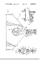
- FIG. 1 show a side elevational view of one embodiment of a feed dispensing hopper according to the present invention
- FIG. 2 shows a front or rear elevational view of the hopper of FIG. 1, depending upon direction of travel of the hopper, with portions broken away for clarity;
- FIG. 3 is a sectional view taken along the section 3--3 in FIG. 2;
- FIG. 4 is a sectional view taken along the section 4--4 in FIG. 1;
- FIG. 5 is a view in perspective of a canopy or hood element which is shown in assembly in FIGS. 1, 2 and 6;
- FIG. 6 is a sectional view taken along the section 6--6 in FIG. 2;
- FIG. 7 is a view similar to FIG. 2, but showing the use of an alternative canopy or hood element.
- FIG. 8 is a view in perspective of the canopy or hood element shown in FIG. 7.
- the present invention is embodied in an improved feed dispensing hopper 10 of the mobile or travelling type and including downwardly extending inclined walls 12 and 14 which converge toward and terminate at the mouth 15 of channel section 16.
- a plurality of feed discharge outlets 20, 22 and 24 At the base 18 of channel 16 is a plurality of feed discharge outlets 20, 22 and 24.
- an auger mechanism 26 is disposed within channel 16 at the base 18 thereof and communicating with outlets 20, 22 and 24 from within hopper 10.
- a feed agitator 28 Suspended from a shaft 52 passing through hopper 10 at a substantial distance above the mouth 15 of channel 16 and extending downwardly therefrom is a feed agitator 28 which comprises a generally rigid plate or like member 30 with a network or plurality of openings 32.
- plate 30 extends down through mouth 15, down into channel 16 for oscillation and/or generally vertical reciprocation thereinto which precludes packing of feed therein to preclude packing of feed thereat.
- the lower end of plate 30 reciprocates without interference with auger mechanism 26, coming within about half an inch of contact therewith, and has a vertical stroke of about half an inch.
- a pair of spaced-apart brackets 34 Secured at the upper end of plate 30.
- Each bracket 34 includes arcuate sleeve portions 36, downwardly extending leg portions 38 and upwardly extending arm portions 40.
- sleeve portions 36 loosely surround bearing members 42, leg portions 38 are clamped to plate 30 by nuts 44 and bolts 46, and arm portions 40 are secured together by nut 48 and bolt 50.
- Each bearing member 42 which may be of low friction material, is secured to shaft 52 in eccentric relationship therewith by a set screw 54.
- Shaft 52 includes a power input end 56 as seen in FIG. 2 and a power output end 58.
- Mounted on output end 58 of shaft 52 is a driving sprocket 60.
- Driving sprocket 60 drives driven sprocket 62 through chain 64.
- Attached to driven sprocket 62 is a shaft portion 66 of auger 26.
- Slack in chain 64 is automatically taken up by tension unit 68 which includes idler sprocket 70 which is rotatably supported on plate 71 pivotally secured to bracket 72.
- Tension spring 74 biases plate 71 and idler sprocket 70 toward chain 64 to automatically take up any slack which may develop.
- a canopy or hood element 76 in the form of an inverted V as seen in FIG. 5 is shown in assembly in FIGS. 1, 2 and 6.
- Canopy 76 as seen in FIGS. 1 and 6 is arranged so that downwardly diverging sides 78,80 provide umbrage over feed agitator 28 and shaft 52 from feed F so that feed is directed generally in the direction of arrows in FIG. 6 on descent due to gravity.
- Canopy 76 may extend for the full distance across hopper 10 and include flanges 82 which may be secured to hopper 10.
- canopy 76 is mounted in hopper 10 so as to be clear of agitator 28, sleeve portions 36, and shaft 52.
- FIGS. 7 and 8 An alternate form of the canopy or hood element 76 is illustrated in FIGS. 7 and 8 in the embodiment of a pyramid 176 suspended above agitator 28 and shaft 52 by any convenient member such as a rod 177 extending across hopper 10.
- Pyramidal canopy 176 comprises a plurality of downwardly diverging sides 178, 180 as seen in FIG. 7 to divert descending feed F outwardly from the central zone of hopper 10.
- notches or cutouts 190 and 192 are provided at the base of canopy 176 in the areas which otherwise might interfere with shaft 52.
- the notches 190 and 192 extend at least partially around shaft 52, but allow freedom of rotation of shaft 52 without interference from canopy 176.
- hopper 10 is driven to the left and/or right from the position illustrated in FIG. 1.
- shaft 52 is driven in at least one direction of travel of the hopper 10, which may for purposes of discussion, be to the left of FIG. 1.
- shaft 52 may be declutched as hopper 10 is traveling toward the right in FIG. 1.
- shaft 52 is rotated and power is delivered to driving sprocket 60 at output end 58 of shaft 52.
- agitator 28 In thus ascending and descending with bearings 42, agitator 28 is raised and lowered thereby and effects a breaking up or chopping of any feed which otherwise would tend to be compacted at or in the vicinity of the mouth 15 of channel 16. Because of the network of openings 32 in the generally rigid plate 30 of agitator 28, feed may be worked back and forth therethrough by the oscillating and/or reciprocating motion of agitator 28, which is caused to move as indicated by two-way arrows in FIGS. 2 and 7.
- canopy 80 by reason of its downwardly diverging sides 78 and 80 provide umbrage for agitator 28, shaft 52 and also mouth 15 of channel 16 to preclude packing of feed F thereabout.
- feed F generally descends down along the top of sides 78 and 80 of canopy 76 and follows the paths generally indicated by arrows and leaves a protected area beneath the underside of sides 78 and 80. With the presence of canopy 76, it is clear that no heavy packing of feed can take place around shaft 52 and agitator 28.
- a pyramidal canopy 176 In an embodiment employing a pyramidal canopy 176, it is noted that while as illustrated in FIG. 7 the base of the canopy does not extend to the sides of hopper 10, the base may be extended thereto. It is also noted that whereas canopy 76 is V-shaped with two diverging sides, in the alternative embodiment of pyramidal canopy, there are the two diverging sides 178,180 and additional diverging sides hidden from view in FIG. 7 and partially shown in FIG. 8. Because of the many diverging sides in pyramidal canopy 176, the feed F diverged or deflected thereby tends to collide with other descending feed and thereby also tends to break up or prevent packing at mouth 15 of channel 16, which funnels feed to auger 26. Canopy 176, as may be seen in FIG. 7, is suspended on rod 177, for example, and is further provided with notches or cutouts 190,192 in the base of sides 178, 180 and sides adjacent thereto whereby shaft 52 may turn freely without interference.
Landscapes
- Life Sciences & Earth Sciences (AREA)
- Environmental Sciences (AREA)
- Birds (AREA)
- Animal Husbandry (AREA)
- Biodiversity & Conservation Biology (AREA)
- Filling Or Emptying Of Bunkers, Hoppers, And Tanks (AREA)
Abstract
Description
Claims (7)
Priority Applications (2)
| Application Number | Priority Date | Filing Date | Title |
|---|---|---|---|
| US05/626,178 US4030452A (en) | 1975-10-28 | 1975-10-28 | Feed dispensing hopper |
| CA244,261A CA1030892A (en) | 1975-10-28 | 1976-01-27 | Feed dispensing hopper |
Applications Claiming Priority (1)
| Application Number | Priority Date | Filing Date | Title |
|---|---|---|---|
| US05/626,178 US4030452A (en) | 1975-10-28 | 1975-10-28 | Feed dispensing hopper |
Publications (1)
| Publication Number | Publication Date |
|---|---|
| US4030452A true US4030452A (en) | 1977-06-21 |
Family
ID=24509284
Family Applications (1)
| Application Number | Title | Priority Date | Filing Date |
|---|---|---|---|
| US05/626,178 Expired - Lifetime US4030452A (en) | 1975-10-28 | 1975-10-28 | Feed dispensing hopper |
Country Status (2)
| Country | Link |
|---|---|
| US (1) | US4030452A (en) |
| CA (1) | CA1030892A (en) |
Cited By (9)
| Publication number | Priority date | Publication date | Assignee | Title |
|---|---|---|---|---|
| US5474027A (en) * | 1993-01-15 | 1995-12-12 | Grain Systems, Inc. | Feed intake cup apparatus |
| US6253966B1 (en) * | 1999-02-12 | 2001-07-03 | Gea Powder Technology Gmbh | Discharge booster for promoting a flow of bulk material |
| US20020112671A1 (en) * | 2001-02-22 | 2002-08-22 | Patterson Lance H. | Feeder for moist fish feed |
| US6681718B1 (en) * | 2002-11-12 | 2004-01-27 | Scott Alan Mcllarky | Animal feeding device |
| US6814029B1 (en) * | 2001-04-11 | 2004-11-09 | Bryan K. Chesser | Deer feeder |
| US20090126639A1 (en) * | 2007-11-15 | 2009-05-21 | Jia Hsiung Hsieh | Apparatus for uniformly distributing materials |
| USD761493S1 (en) * | 2015-08-13 | 2016-07-12 | Darlene Lowenthal | Pet food storage device |
| CN107624667A (en) * | 2017-11-10 | 2018-01-26 | 耒阳市晓田牧业有限责任公司 | A kind of high pig drinking trough of applicability |
| US11766023B2 (en) | 2019-12-09 | 2023-09-26 | The Gsi Group Llc | Livestock feed tank with modular unloader |
Citations (7)
| Publication number | Priority date | Publication date | Assignee | Title |
|---|---|---|---|---|
| US1346025A (en) * | 1919-08-26 | 1920-07-06 | Ora W Hiner | Automatic stock-feeder |
| US2011340A (en) * | 1931-11-27 | 1935-08-13 | George A Lundy | Lime and fertilizer spreader or seeder |
| US2633133A (en) * | 1950-02-15 | 1953-03-31 | Claude S Hay | Cigarette making machine |
| US2967056A (en) * | 1955-10-28 | 1961-01-03 | Seaman Andwall Corp | Material spreaders for dump trucks |
| US3152575A (en) * | 1962-08-22 | 1964-10-13 | James A Singley | Animal feeder |
| US3173582A (en) * | 1961-03-15 | 1965-03-16 | Julian L Walter | Feed mixer |
| US3742913A (en) * | 1972-03-08 | 1973-07-03 | Coleswood Prod Inc | Automatic feeding device for animals |
-
1975
- 1975-10-28 US US05/626,178 patent/US4030452A/en not_active Expired - Lifetime
-
1976
- 1976-01-27 CA CA244,261A patent/CA1030892A/en not_active Expired
Patent Citations (7)
| Publication number | Priority date | Publication date | Assignee | Title |
|---|---|---|---|---|
| US1346025A (en) * | 1919-08-26 | 1920-07-06 | Ora W Hiner | Automatic stock-feeder |
| US2011340A (en) * | 1931-11-27 | 1935-08-13 | George A Lundy | Lime and fertilizer spreader or seeder |
| US2633133A (en) * | 1950-02-15 | 1953-03-31 | Claude S Hay | Cigarette making machine |
| US2967056A (en) * | 1955-10-28 | 1961-01-03 | Seaman Andwall Corp | Material spreaders for dump trucks |
| US3173582A (en) * | 1961-03-15 | 1965-03-16 | Julian L Walter | Feed mixer |
| US3152575A (en) * | 1962-08-22 | 1964-10-13 | James A Singley | Animal feeder |
| US3742913A (en) * | 1972-03-08 | 1973-07-03 | Coleswood Prod Inc | Automatic feeding device for animals |
Cited By (10)
| Publication number | Priority date | Publication date | Assignee | Title |
|---|---|---|---|---|
| US5474027A (en) * | 1993-01-15 | 1995-12-12 | Grain Systems, Inc. | Feed intake cup apparatus |
| US6253966B1 (en) * | 1999-02-12 | 2001-07-03 | Gea Powder Technology Gmbh | Discharge booster for promoting a flow of bulk material |
| US20020112671A1 (en) * | 2001-02-22 | 2002-08-22 | Patterson Lance H. | Feeder for moist fish feed |
| US6571736B2 (en) * | 2001-02-22 | 2003-06-03 | Lance H. Patterson | Feeder for moist fish feed |
| US6814029B1 (en) * | 2001-04-11 | 2004-11-09 | Bryan K. Chesser | Deer feeder |
| US6681718B1 (en) * | 2002-11-12 | 2004-01-27 | Scott Alan Mcllarky | Animal feeding device |
| US20090126639A1 (en) * | 2007-11-15 | 2009-05-21 | Jia Hsiung Hsieh | Apparatus for uniformly distributing materials |
| USD761493S1 (en) * | 2015-08-13 | 2016-07-12 | Darlene Lowenthal | Pet food storage device |
| CN107624667A (en) * | 2017-11-10 | 2018-01-26 | 耒阳市晓田牧业有限责任公司 | A kind of high pig drinking trough of applicability |
| US11766023B2 (en) | 2019-12-09 | 2023-09-26 | The Gsi Group Llc | Livestock feed tank with modular unloader |
Also Published As
| Publication number | Publication date |
|---|---|
| CA1030892A (en) | 1978-05-09 |
Similar Documents
| Publication | Publication Date | Title |
|---|---|---|
| US4030452A (en) | Feed dispensing hopper | |
| US3693890A (en) | Material spreader attachment for trucks | |
| US6047863A (en) | Apparatus and agitator for dispensing fluent material into containers | |
| US5740950A (en) | Apparatus and agitator for dispensing fluent material into containers | |
| US3642254A (en) | Means for conveying, discharging and mixing livestock feeds | |
| US2774602A (en) | Material spreading apparatus | |
| US3229828A (en) | Material handling apparatus | |
| US2705474A (en) | Automatic feeder for poultry and the like | |
| US2446472A (en) | Adaptable conveyer | |
| US3842967A (en) | Rotatable distributor-feeders to traveling receptacles | |
| US2673741A (en) | Fertilizer spreader | |
| US3159142A (en) | Animal feeder system | |
| US4363447A (en) | Chip spreader | |
| US4130223A (en) | Feed level monitor and control apparatus | |
| DE1917570B2 (en) | Device for the filling or conveying of at least partially fluidized powdery or granular material with a constant amount of time | |
| US2141691A (en) | Dispensing device | |
| US2058976A (en) | Can conveying and filling device | |
| US2798645A (en) | Agitator for bins and the like | |
| US2759614A (en) | Anti-clogging device | |
| US3817216A (en) | Feed distributing apparatus | |
| GB2037559A (en) | Dispensing granular materials | |
| US3443547A (en) | Shuttle type animal feeder | |
| US2813722A (en) | Fertilizer distributor | |
| US723971A (en) | Conveyer. | |
| US2071495A (en) | Sand spreader |
Legal Events
| Date | Code | Title | Description |
|---|---|---|---|
| AS | Assignment |
Owner name: DIAMOND AUTOMATIONS, INC., 23400 HAGGERTY ROAD, FA Free format text: ASSIGNMENT OF ASSIGNORS INTEREST.;ASSIGNOR:DIAMOND INTERNATIONAL CORPORATION;REEL/FRAME:004157/0383 Effective date: 19830627 Owner name: DIAMOND AUTOMATIONS, INC., MICHIGAN Free format text: ASSIGNMENT OF ASSIGNORS INTEREST;ASSIGNOR:DIAMOND INTERNATIONAL CORPORATION;REEL/FRAME:004157/0383 Effective date: 19830627 |
|
| AS | Assignment |
Owner name: BIG DUTCHMAN, P.O. BOX NINE (ROUTE 322 WEST), NEW Free format text: ASSIGNMENT OF ASSIGNORS INTEREST.;ASSIGNOR:DIAMOND AUTOMATIONS, INC.;REEL/FRAME:004763/0653 Effective date: 19870706 Owner name: BIG DUTCHMAN,PENNSYLVANIA Free format text: ASSIGNMENT OF ASSIGNORS INTEREST;ASSIGNOR:DIAMOND AUTOMATIONS, INC.;REEL/FRAME:004763/0653 Effective date: 19870706 |
|
| AS | Assignment |
Owner name: CYCLONE INTERNATIONAL INC., A CORP. OF MI., MICHIG Free format text: ASSIGNMENT OF ASSIGNORS INTEREST.;ASSIGNOR:BIG DUTCHMAN;REEL/FRAME:005240/0992 Effective date: 19890814 |
|
| AS | Assignment |
Owner name: BIG DUTCHMAN CYCLONE, INC. Free format text: CHANGE OF NAME;ASSIGNOR:CYCLONE INTERNATONAL INC. (CHANGED TO);REEL/FRAME:005238/0224 Effective date: 19891212 |