US4004102A - Automatic impedance modification of transmission lines - Google Patents
Automatic impedance modification of transmission lines Download PDFInfo
- Publication number
- US4004102A US4004102A US05/602,988 US60298875A US4004102A US 4004102 A US4004102 A US 4004102A US 60298875 A US60298875 A US 60298875A US 4004102 A US4004102 A US 4004102A
- Authority
- US
- United States
- Prior art keywords
- impedance
- line
- signal
- amplifier
- signals
- Prior art date
- Legal status (The legal status is an assumption and is not a legal conclusion. Google has not performed a legal analysis and makes no representation as to the accuracy of the status listed.)
- Expired - Lifetime
Links
- 230000005540 biological transmission Effects 0.000 title claims abstract description 34
- 230000004048 modification Effects 0.000 title 1
- 238000012986 modification Methods 0.000 title 1
- 239000003990 capacitor Substances 0.000 claims description 18
- 230000005669 field effect Effects 0.000 claims description 6
- 238000001914 filtration Methods 0.000 claims 1
- 238000001228 spectrum Methods 0.000 claims 1
- 230000002457 bidirectional effect Effects 0.000 description 24
- 230000000694 effects Effects 0.000 description 10
- 230000001902 propagating effect Effects 0.000 description 5
- 239000004020 conductor Substances 0.000 description 2
- 238000010586 diagram Methods 0.000 description 2
- 238000000926 separation method Methods 0.000 description 2
- 230000000903 blocking effect Effects 0.000 description 1
- 238000010276 construction Methods 0.000 description 1
- 238000007796 conventional method Methods 0.000 description 1
- 238000002592 echocardiography Methods 0.000 description 1
- 238000009434 installation Methods 0.000 description 1
- 230000002093 peripheral effect Effects 0.000 description 1
- 230000035945 sensitivity Effects 0.000 description 1
Images

Classifications
-
- H—ELECTRICITY
- H04—ELECTRIC COMMUNICATION TECHNIQUE
- H04B—TRANSMISSION
- H04B3/00—Line transmission systems
- H04B3/02—Details
- H04B3/40—Artificial lines; Networks simulating a line of certain length
Definitions
- the invention automatically modifies the impedance characteristics of a transmission line as the line is transmitting an intelligence signal by comparing voltages indicative of the signal current and signal voltage in an impedance monitor.
- the amplitude of at least one of the signals is changed to produce a pair of signals that have a substantially equal amplitude when the signal current and voltage are indicative of a prescribed impedance.
- the amplitude of the pair of signals are then compared to each other to produce a control signal indicative of the impedance of the transmission line.
- An impedance matching network responsive to the amplitude of the control signal produced by the impedance monitor adjusts the shunting resistance across the transmission line in accordance with the amplitude to provide low frequency compensation.
- FIG. 3 is a table illustrating typical transmission lines for which the invention may be utilized to provide impedance compensation.
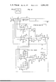
- FIGS. 1A and 1B which should be oriented in accordance with FIG. 2, are sections of a detailed diagram of a complete illustrative embodiment of the invention.
- transformer 11 couples an intelligence signal through serial resistor 12 to bidirectional amplifier 13 which may be any type of repeater including a negative impedance repeater or a hybrid amplifier.
- the other end of amplifier 13 is connected to a two-wire bidirectional transmission line 14 which, in turn, is coupled through compensator 16 to transformer 30.
- the side of transformer 30 connected to transmission 14 is shunted by compensators 21 and 28 and fixed capacitor 15.
- the described arrangement may be utilized at any convenient location in the telephone transmission system. Furthermore, the arrangement may be utilized without a repeater such as bidirectional amplifier 13.
- transformer 11 is connected to an internal switching stage of the telephone central office while transformer 30 is connected to a peripheral switching stage of the telephone central office which couples the concentrated link to any one of a number of telephone subscriber loops such as telephone subscriber loop 31 in FIG. 1B.
- the impedance of the particular telephone subscriber loop connected to transformer 30 therefore has an unknown value, but the most likely kind of telephone subscriber loop coupled to the switching stage is a long loop of relatively high resistance so that the gain of bidirectional amplifier 13 offsets the signal loss.
- the impedance characteristic of telephone subscriber loop 31 is to be automatically modified by the disclosed arrangement to match the output of bidirectional amplifier 13.
- this type of subscriber loop is of the loaded variety, for example, H-88 loaded cable (88 millihenry load coils are serially spaced 6000 feet apart in the cable).
- the active elements of impedance monitor 32 comprise operational amplifiers 33, 34 and 54.
- Amplifier 33 serves to magnify the voltage drop across resistor 12 which is coupled to it through resistors 36 and 37.
- the gain of amplifier 33 is fixed by the ratio of the resistivity of resistor 38 divided by the value of resistor 36 and the ratio of the values of resistor 39 to 37 wherein both ratios are equal to each other.
- the product of the gain of amplifier 33 and the value of resistor 12 produce a factor which partially determines the magnitude of the output voltage of that amplifier. This factor times the current I L flowing through resistor 12 produces the output voltage of amplifier 33.
- a 34 Gain of amplifier 34.
- a positive signal from amplifier 54 indicates that the magnitude of the input impedance of bidirectional amplifier 13 is greater than the prescribed input impedance of the bidirectional amplifier.
- the output of amplifier 54 is negative.
- the output signal of amplifier 54 is applied to a level shifter circuit comprising resistors 58 and 59 wherein the junction of these resistors provides a signal of one polarity whose amplitude is proportional to the value of the impedance monitored by impedance monitor 32.
- the output of impedance monitor 32 is applied to switch 62 which is controlled by directional sensor 63.
- Similar limiter operation is achieved by amplifier 65 through the action of oppositely poled diodes 74 and 76 which shunt resistor 73.
- the relative value of resistor 73 to resistor 72 determines the gain when amplifier 65 operates linearly or swings between the two clamped or limited voltage levels.
- the output of limiters 64 and 65 are applied to the separate differential inputs of amplifiers 81 via resistors 78 and 79.
- Amplifier 81 provides a positive output in accordance with the phase relationship between the instantaneous signal voltage and signal current of signals propagating from transformer 11 to transformer 30.
- the positive output of amplifier 81 is conducted by diode 84 to resistor 87 and turns on transistor 88.
- High frequency compensation is accomplished with compensator 16, fixed build out capacitor 15, and variable high frequency compensator 28.
- FET 93 changes resistance in response to the control signal on conductor 92.
- FET 93 shunts resistor 94 through serial capacitor 96 and serves to lower the effective emitter resistance of the common emitter amplifier including transistors 97 and 98.
- the collectors of transistors 97 and 98 are biased by resistor 100 while the base of transistor 98 is biased through resistors 102 and 103.
- FET 93 changes the gain of transistors 97 and 98, the effective input capacitance between the terminals of compensator 28 varies due to the Miller effect on feedback capacitor 99.
- compensator 21 has considerable effect on the impedance of line 14 at frequencies below 1000 Hz and very little effect on frequencies above 1000 Hz.
- compensator 28 has very little effect on the impedance of transmission line 14 below 1000 Hz and a significant effect on impedances above that frequency.
- impedance monitor 32 is only sensitive to the magnitude of the impedance on transmission line 14.
- compensators 21 and 28 must be designed so that as the magnitude of the impedance is corrected the phase angle of the impedance will not have a significant effect upon the operation of the circuit. Compensation of phase angle shift, which is more significant at higher frequencies, i.e., above 1000 Hz, is provided by compensator 16.
- Compensator 16 includes resistor 17, capacitor 18 and inductor 19 which form a parallel resonant circuit. The values of these components are selected so that the phase angle of impedance throughout the variable range of compensators 21 and 28 is kept within 25° of 0° and when the compensators are properly adjusted the phase angle will be within 10° of 0° .
- compensator 21 provides the effective compensation while compensator 28 is improperly adjusted, but it has no significant effect upon the operation.
- impedance monitor 32 produces a signal which corresponds to an average adjustment which will provide satisfactory impedance compensation for bidirectional amplifier 13.
- FIG. 3 lists the range of values of representative loops for typical cables for which the illustrative embodiment herein disclosed will adequately compensate.
- the two right-hand columns of FIG. 3 list the actual values of capacitance required from variable compensator 28 in shunt with transmission line 14 to effect the impedance compensation at the two typical frequencies listed.
- the values of resistance in FIG. 3 are those required by variable compensator 21 to effect impedance compensation for each type of cable at the frequency listed.
- all of the cables listed in FIG. 3 are H88 loaded cable, other types of loaded cables may be advantageously compensated using the inventive concept disclosed herein.
- the end section column in FIG. 3 represents the distance from transformer 30 to the first load coil in the cable.
Landscapes
- Engineering & Computer Science (AREA)
- Computer Networks & Wireless Communication (AREA)
- Signal Processing (AREA)
- Cable Transmission Systems, Equalization Of Radio And Reduction Of Echo (AREA)
- Networks Using Active Elements (AREA)
Priority Applications (6)
| Application Number | Priority Date | Filing Date | Title |
|---|---|---|---|
| US05/602,988 US4004102A (en) | 1975-08-08 | 1975-08-08 | Automatic impedance modification of transmission lines |
| GB30237/76A GB1544866A (en) | 1975-08-08 | 1976-07-20 | Automatic impedance of transmission lines |
| CA257989A CA1054689A (en) | 1975-08-08 | 1976-07-28 | Automatic impedance modification of transmission lines |
| FR7623695A FR2320669A1 (fr) | 1975-08-08 | 1976-08-03 | Appareil de modification automatique de l'impedance des lignes de transmission |
| AU16564/76A AU500854B2 (en) | 1975-08-08 | 1976-08-04 | Automatic impedance modification of transmission lines |
| DE19762635021 DE2635021A1 (de) | 1975-08-08 | 1976-08-04 | Schaltungsanordnung zur aenderung der impedanzeigenschaften einer uebertragungsleitung |
Applications Claiming Priority (1)
| Application Number | Priority Date | Filing Date | Title |
|---|---|---|---|
| US05/602,988 US4004102A (en) | 1975-08-08 | 1975-08-08 | Automatic impedance modification of transmission lines |
Publications (1)
| Publication Number | Publication Date |
|---|---|
| US4004102A true US4004102A (en) | 1977-01-18 |
Family
ID=24413589
Family Applications (1)
| Application Number | Title | Priority Date | Filing Date |
|---|---|---|---|
| US05/602,988 Expired - Lifetime US4004102A (en) | 1975-08-08 | 1975-08-08 | Automatic impedance modification of transmission lines |
Country Status (6)
| Country | Link |
|---|---|
| US (1) | US4004102A (Direct) |
| AU (1) | AU500854B2 (Direct) |
| CA (1) | CA1054689A (Direct) |
| DE (1) | DE2635021A1 (Direct) |
| FR (1) | FR2320669A1 (Direct) |
| GB (1) | GB1544866A (Direct) |
Cited By (18)
| Publication number | Priority date | Publication date | Assignee | Title |
|---|---|---|---|---|
| US4181824A (en) * | 1978-10-10 | 1980-01-01 | Bell Telephone Laboratories, Incorporated | Balancing impedance circuit |
| US4273963A (en) * | 1979-05-25 | 1981-06-16 | Bell Telephone Laboratories, Incorporated | Automatic equalization for digital transmission systems |
| US4289933A (en) * | 1979-10-15 | 1981-09-15 | Bell Telephone Laboratories, Incorporated | Dial pulse detection |
| US4445222A (en) * | 1978-10-30 | 1984-04-24 | Christian Rovsing A/S | Coupling circuit for transferring data signals at a high rate |
| US4856058A (en) * | 1984-09-28 | 1989-08-08 | Kabushiki Kaisha Toshiba | Office line interface circuits |
| WO1992015952A1 (en) * | 1991-02-27 | 1992-09-17 | Astec America, Inc. | Automatic impedance matching apparatus and method |
| US5249225A (en) * | 1991-10-25 | 1993-09-28 | Coherent Communications Systems Corp. | Self-balancing hybrid using digitally programmable attenuator for variable impedance elements |
| US5258713A (en) * | 1992-04-16 | 1993-11-02 | Northern Telecom Limited | Impedance generator for a telephone line interface circuit |
| US5271059A (en) * | 1990-01-29 | 1993-12-14 | Siemens Aktiengesellschaft | Method and configuration for forming a line termination of a telephone line |
| US5282157A (en) * | 1990-09-13 | 1994-01-25 | Telecom Analysis Systems, Inc. | Input impedance derived from a transfer network |
| US5410594A (en) * | 1990-03-02 | 1995-04-25 | Kabushiki Kaisha Toshiba | Transmission input/output device with reduced power consumption |
| US5471527A (en) | 1993-12-02 | 1995-11-28 | Dsc Communications Corporation | Voice enhancement system and method |
| WO1998021868A3 (en) * | 1996-11-08 | 1998-07-16 | Ericsson Telefon Ab L M | Arrangement in a subscriber line interface circuit |
| US6198817B1 (en) * | 1998-01-23 | 2001-03-06 | International Business Machines Corporation | Communication interface having combined shaping of receive response and synthesized matching terminating impedances for different frequency bands and a design method therefor |
| EP1079591A3 (en) * | 1999-08-23 | 2003-06-04 | Intersil Corporation | Loop impedance measuring apparatus and method for subscriber loop interface circuits |
| US20080144546A1 (en) * | 2005-01-23 | 2008-06-19 | Serconet Ltd. | Device, method and system for estimating the termination to a wired transmission-line based on determination of characteristic impedance |
| US10886892B2 (en) * | 2017-02-20 | 2021-01-05 | Murata Manufacturing Co., Ltd. | Filter apparatus, multiplexer, radio-frequency front end circuit, and communication apparatus |
| CN117330799A (zh) * | 2023-11-28 | 2024-01-02 | 深圳市鼎阳科技股份有限公司 | 一种阻抗匹配电路、差分探头及示波器 |
Citations (5)
| Publication number | Priority date | Publication date | Assignee | Title |
|---|---|---|---|---|
| US3578914A (en) * | 1969-04-09 | 1971-05-18 | Lynch Communication Systems | Equalizer with automatic line build-out |
| US3582563A (en) * | 1967-01-04 | 1971-06-01 | Int Standard Electric Corp | Apparatus for matching the impedance of a telephone set to a line |
| US3671676A (en) * | 1969-12-17 | 1972-06-20 | Bell Telephone Labor Inc | Subscriber loop range extender |
| US3706862A (en) * | 1971-06-28 | 1972-12-19 | Lorain Prod Corp | Amplifier circuit for transmission lines |
| US3818151A (en) * | 1973-01-26 | 1974-06-18 | Lorain Prod Corp | Method and apparatus for amplifying signal transmission through transmission lines |
-
1975
- 1975-08-08 US US05/602,988 patent/US4004102A/en not_active Expired - Lifetime
-
1976
- 1976-07-20 GB GB30237/76A patent/GB1544866A/en not_active Expired
- 1976-07-28 CA CA257989A patent/CA1054689A/en not_active Expired
- 1976-08-03 FR FR7623695A patent/FR2320669A1/fr active Granted
- 1976-08-04 DE DE19762635021 patent/DE2635021A1/de not_active Withdrawn
- 1976-08-04 AU AU16564/76A patent/AU500854B2/en not_active Expired
Patent Citations (5)
| Publication number | Priority date | Publication date | Assignee | Title |
|---|---|---|---|---|
| US3582563A (en) * | 1967-01-04 | 1971-06-01 | Int Standard Electric Corp | Apparatus for matching the impedance of a telephone set to a line |
| US3578914A (en) * | 1969-04-09 | 1971-05-18 | Lynch Communication Systems | Equalizer with automatic line build-out |
| US3671676A (en) * | 1969-12-17 | 1972-06-20 | Bell Telephone Labor Inc | Subscriber loop range extender |
| US3706862A (en) * | 1971-06-28 | 1972-12-19 | Lorain Prod Corp | Amplifier circuit for transmission lines |
| US3818151A (en) * | 1973-01-26 | 1974-06-18 | Lorain Prod Corp | Method and apparatus for amplifying signal transmission through transmission lines |
Cited By (22)
| Publication number | Priority date | Publication date | Assignee | Title |
|---|---|---|---|---|
| US4181824A (en) * | 1978-10-10 | 1980-01-01 | Bell Telephone Laboratories, Incorporated | Balancing impedance circuit |
| US4445222A (en) * | 1978-10-30 | 1984-04-24 | Christian Rovsing A/S | Coupling circuit for transferring data signals at a high rate |
| US4273963A (en) * | 1979-05-25 | 1981-06-16 | Bell Telephone Laboratories, Incorporated | Automatic equalization for digital transmission systems |
| US4289933A (en) * | 1979-10-15 | 1981-09-15 | Bell Telephone Laboratories, Incorporated | Dial pulse detection |
| US4856058A (en) * | 1984-09-28 | 1989-08-08 | Kabushiki Kaisha Toshiba | Office line interface circuits |
| US5271059A (en) * | 1990-01-29 | 1993-12-14 | Siemens Aktiengesellschaft | Method and configuration for forming a line termination of a telephone line |
| US5410594A (en) * | 1990-03-02 | 1995-04-25 | Kabushiki Kaisha Toshiba | Transmission input/output device with reduced power consumption |
| US5282157A (en) * | 1990-09-13 | 1994-01-25 | Telecom Analysis Systems, Inc. | Input impedance derived from a transfer network |
| WO1992015952A1 (en) * | 1991-02-27 | 1992-09-17 | Astec America, Inc. | Automatic impedance matching apparatus and method |
| US5195045A (en) * | 1991-02-27 | 1993-03-16 | Astec America, Inc. | Automatic impedance matching apparatus and method |
| US5249225A (en) * | 1991-10-25 | 1993-09-28 | Coherent Communications Systems Corp. | Self-balancing hybrid using digitally programmable attenuator for variable impedance elements |
| US5258713A (en) * | 1992-04-16 | 1993-11-02 | Northern Telecom Limited | Impedance generator for a telephone line interface circuit |
| US5471527A (en) | 1993-12-02 | 1995-11-28 | Dsc Communications Corporation | Voice enhancement system and method |
| US6263076B1 (en) | 1996-11-08 | 2001-07-17 | Telefonaktiebolaget Lm Ericsson (Publ) | Arrangement in a subscriber line interface circuit |
| WO1998021868A3 (en) * | 1996-11-08 | 1998-07-16 | Ericsson Telefon Ab L M | Arrangement in a subscriber line interface circuit |
| US6198817B1 (en) * | 1998-01-23 | 2001-03-06 | International Business Machines Corporation | Communication interface having combined shaping of receive response and synthesized matching terminating impedances for different frequency bands and a design method therefor |
| EP1079591A3 (en) * | 1999-08-23 | 2003-06-04 | Intersil Corporation | Loop impedance measuring apparatus and method for subscriber loop interface circuits |
| US20080144546A1 (en) * | 2005-01-23 | 2008-06-19 | Serconet Ltd. | Device, method and system for estimating the termination to a wired transmission-line based on determination of characteristic impedance |
| US7919970B2 (en) * | 2005-01-23 | 2011-04-05 | Mosaid Technologies Incorporated | Device, method and system for estimating the termination to a wired transmission-line based on determination of characteristic impedance |
| US10886892B2 (en) * | 2017-02-20 | 2021-01-05 | Murata Manufacturing Co., Ltd. | Filter apparatus, multiplexer, radio-frequency front end circuit, and communication apparatus |
| CN117330799A (zh) * | 2023-11-28 | 2024-01-02 | 深圳市鼎阳科技股份有限公司 | 一种阻抗匹配电路、差分探头及示波器 |
| CN117330799B (zh) * | 2023-11-28 | 2024-03-01 | 深圳市鼎阳科技股份有限公司 | 一种阻抗匹配电路、差分探头及示波器 |
Also Published As
| Publication number | Publication date |
|---|---|
| FR2320669B1 (Direct) | 1980-04-25 |
| DE2635021A1 (de) | 1977-02-24 |
| AU1656476A (en) | 1978-02-09 |
| AU500854B2 (en) | 1979-06-07 |
| GB1544866A (en) | 1979-04-25 |
| FR2320669A1 (fr) | 1977-03-04 |
| CA1054689A (en) | 1979-05-15 |
Similar Documents
| Publication | Publication Date | Title |
|---|---|---|
| US4004102A (en) | Automatic impedance modification of transmission lines | |
| US3973089A (en) | Adaptive hybrid circuit | |
| US4096361A (en) | Test apparatus for obtaining impedance settings for hybrid balance networks | |
| US4096362A (en) | Automatic cable balancing network | |
| US4472608A (en) | Subscriber line interface circuit | |
| US4074087A (en) | Bidirectional voice frequency repeater | |
| US4103118A (en) | Autobalance hybrid circuit | |
| US4331842A (en) | Voice frequency repeater and term sets and other circuits therefor | |
| FI63141B (fi) | Elektronisk telefonkrets | |
| US4007340A (en) | Distance-related variable gain amplifier | |
| US5249224A (en) | Methods and apparatus for providing reciprocal impedance conversion | |
| EP0371468B1 (en) | Side tone preventive circuit for telephone | |
| US3204048A (en) | Negative impedance repeaters for non-loaded lines | |
| US4538032A (en) | Interface circuit with impedance adaptation means | |
| US3989906A (en) | Repeater for transmission lines | |
| CA1143492A (en) | Interface circuits | |
| US4037066A (en) | Repeater for transmission lines | |
| US3431351A (en) | Method of transmitting television signals | |
| US3083265A (en) | Conference call circuit | |
| US4028505A (en) | Negative impedance repeater for telephone lines | |
| CA1078536A (en) | Bilateral voice-signal controller for use in the two-wire portion of the telephone circuit | |
| US4176255A (en) | Adjustable impedance battery feed circuit | |
| US3814866A (en) | Negative resistance repeater | |
| US4135064A (en) | Impedance compensation of transmission line | |
| US4942603A (en) | Methods and apparatus for providing reciprocal impedance conversion |