US3994251A - Apparatus and method for trimming and deburring the edges of cylindrical metal bodies - Google Patents
Apparatus and method for trimming and deburring the edges of cylindrical metal bodies Download PDFInfo
- Publication number
- US3994251A US3994251A US05/631,513 US63151375A US3994251A US 3994251 A US3994251 A US 3994251A US 63151375 A US63151375 A US 63151375A US 3994251 A US3994251 A US 3994251A
- Authority
- US
- United States
- Prior art keywords
- support means
- burr
- cylindrical portion
- cylindrical
- ironing
- Prior art date
- Legal status (The legal status is an assumption and is not a legal conclusion. Google has not performed a legal analysis and makes no representation as to the accuracy of the status listed.)
- Expired - Lifetime
Links
Images
Classifications
-
- B—PERFORMING OPERATIONS; TRANSPORTING
- B21—MECHANICAL METAL-WORKING WITHOUT ESSENTIALLY REMOVING MATERIAL; PUNCHING METAL
- B21D—WORKING OR PROCESSING OF SHEET METAL OR METAL TUBES, RODS OR PROFILES WITHOUT ESSENTIALLY REMOVING MATERIAL; PUNCHING METAL
- B21D19/00—Flanging or other edge treatment, e.g. of tubes
- B21D19/005—Edge deburring or smoothing
-
- Y—GENERAL TAGGING OF NEW TECHNOLOGICAL DEVELOPMENTS; GENERAL TAGGING OF CROSS-SECTIONAL TECHNOLOGIES SPANNING OVER SEVERAL SECTIONS OF THE IPC; TECHNICAL SUBJECTS COVERED BY FORMER USPC CROSS-REFERENCE ART COLLECTIONS [XRACs] AND DIGESTS
- Y10—TECHNICAL SUBJECTS COVERED BY FORMER USPC
- Y10T—TECHNICAL SUBJECTS COVERED BY FORMER US CLASSIFICATION
- Y10T82/00—Turning
- Y10T82/16—Severing or cut-off
- Y10T82/16016—Processes
-
- Y—GENERAL TAGGING OF NEW TECHNOLOGICAL DEVELOPMENTS; GENERAL TAGGING OF CROSS-SECTIONAL TECHNOLOGIES SPANNING OVER SEVERAL SECTIONS OF THE IPC; TECHNICAL SUBJECTS COVERED BY FORMER USPC CROSS-REFERENCE ART COLLECTIONS [XRACs] AND DIGESTS
- Y10—TECHNICAL SUBJECTS COVERED BY FORMER USPC
- Y10T—TECHNICAL SUBJECTS COVERED BY FORMER US CLASSIFICATION
- Y10T82/00—Turning
- Y10T82/16—Severing or cut-off
- Y10T82/16426—Infeed means
- Y10T82/16655—Infeed means with means to rotate tool[s]
- Y10T82/16688—Planetating work mandrels
-
- Y—GENERAL TAGGING OF NEW TECHNOLOGICAL DEVELOPMENTS; GENERAL TAGGING OF CROSS-SECTIONAL TECHNOLOGIES SPANNING OVER SEVERAL SECTIONS OF THE IPC; TECHNICAL SUBJECTS COVERED BY FORMER USPC CROSS-REFERENCE ART COLLECTIONS [XRACs] AND DIGESTS
- Y10—TECHNICAL SUBJECTS COVERED BY FORMER USPC
- Y10T—TECHNICAL SUBJECTS COVERED BY FORMER US CLASSIFICATION
- Y10T82/00—Turning
- Y10T82/16—Severing or cut-off
- Y10T82/16426—Infeed means
- Y10T82/16967—Infeed means with means to support and/or rotate work
Definitions
- a more specific object is to provide such a method and apparatus which are particularly adapted for the production of container shells by draw-redraw and drawing and ironing techniques and, in particular, for producing such shells from steel and aluminum blanks.
- an apparatus having support means upon which a cylindrical metal body may be mounted, and including a cutting element and a cylindrical portion.
- a cutting tool is disposed adjacent the cutting element, and is adapted to cooperate therewith to sever an edge portion of the metal body mounted on the support means, and to form an inwardly-directed burr at the newly-formed edge thereof.
- An ironing tool is disposed adjacent the cylindrical portion, and is adapted to cooperate therewith to iron a portion of a metal body disposed thereon.
- the apparatus additionally includes means for shifting the body axially on the support means away from the cutting element so that, following severance and internal burr formation, the burr-bearing portion of the body may be moved onto the cylindrical portion, to permit ironing of the burr thereat and to thereby effect its fracture and removal.
- the support means is rotatable, and includes a substantially cylindrical mandrel disposed axially adjacent the cylindrical portion thereof.
- the cylindrical portion advantageously has a relatively sharp edge, which is spaced from the mandrel and which provides the cutting element.
- the apparatus also includes a rotatable support member, such as a wheel, on which both the cutting tool and also the ironing tool are mounted, at axially- and peripherally-spaced locations.
- the support means is mounted on a first shaft and the rotatable support member is mounted on a second shaft, the shafts being rotatable on substantially parallel axes, and being interconnected to afford synchronized rotation of the support means and support member.
- a trimming and deburring method which includes, as an initial step, mounting a cylindrical metal body on support means having a cylindrical portion. An edge portion is then severed from the body, so as to form an inwardly-directed burr at the newly-formed edge, after which the body is shifted axially on the support means to move the burr-bearing edge onto the cylindrical portion. Finally, the burr is ironed against the surface of the cylindrical portion to effect its fracture and removal from the remainder of the body.
- the body is rotated while performing the severing and ironing steps, and generally the body will be the shell for a drawn and ironed or draw-redraw container.
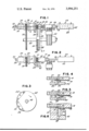
- FIG. 1 is a fragmentary, elevational view of trimming and deburring apparatus embodying the present invention, and showing an untrimmed can shell prior to loading onto the mandrel assembly;
- FIG. 2 is a view similar to that of FIG. 1, with portions removed and showing a phase of operation in which the untrimmed can shell is loaded onto the mandrel assembly;
- FIG. 3 is an end view of the tool-supporting wheel used in the apparatus of the foregoing figures, taken along line 3--3 of FIG. 1;
- FIG. 4 is an enlarged, fragmentary view of thee apparatus, showing the cutting elements in operation
- FIG. 5 is a view similar to that of FIG. 4, showing the can body shifted on the body-support means, with the burr portion positioned for ironing;
- FIG. 6 is a view comparable to that of FIGS. 4 and 5, showing the ironing elements in operation.
- the mandrel assembly 10 includes a spindle 11, which is rotatably mounted within a bearing housing 13 (supported on a base by appropriate means, neither of which is shown), and carries a cylindrical mandrel member 18 at one end, a driven pinion 38 at the opposite end, a serrated cylindrical portion 37 adjacent the housing 13, and a work disc 20 interposed between the serrated portion 37 and the mandrel member 18.
- the disc 20 has a relatively smooth, cylindrical outer surface, and a sharp edge 24 at the end remote from the mandrel member 18.
- an axial passageway 12 Extending through the spindle 11 is an axial passageway 12, in which is received the rod 28 of a piston sub-assembly, generally designated by the numeral 29.
- a piston sub-assembly mounted on the forward end of the rod 28 is a generally cylindrical push member 26; the opposite end of the piston rod 28 is disposed within the cylinder 36 of a pneumatic unit supported adjacent the bearing housing 13 (by means not shown), and carries a piston head 34.
- control of the position of the head 34 within the cylinder 36 is achieved by the introduction and withdrawal of air into and from the cylinder 36, in turn effecting axial movement of the push member 26 (for a purpose to be explained in detail hereinafter).
- the piston rod 28 also has a small bore 30 extending through it, and a hose 32 coupled to its rearward end provides communication with a source (not shown) of compressed air.
- a shaft 40 which rotates about an axis parallel to that of the spindle 11.
- the shaft 40 has supported on it a multi-pocketed can carrying turret 52, and affixed to it a drive gear 39, in meshing engagement with the pinion 38 on the spindle 11, and a tool carrier wheel 42 disposed between the turret 52 and the gear 39.
- a cutting tool sector 44 having a relatively sharp edge 46
- an ironing tool sector 48 having a cylindrical surface position 49
- a corrugated scrap knurling sector 50 mounted on the wheel 42.
- the apparatus illustrated also includes a loading mechanism, generally designated by the numeral 53, consisting of a hydraulically-operated cylinder 62, in which is mounted a piston rod 56 having a piston head 60 at one end and a loading chuck 58 affixed to the opposite end thereof.
- a loading mechanism generally designated by the numeral 53, consisting of a hydraulically-operated cylinder 62, in which is mounted a piston rod 56 having a piston head 60 at one end and a loading chuck 58 affixed to the opposite end thereof.
- an untrimmed can shell or body 70 supported in a pocket provided by the cradle elements 54 of the turret 52, is presented thereby into axial alignment between the mandrel assembly 10 and the loading mechanism 53.
- hydraulic fluid is introduced into the cylinder 62, moving the piston head 60, and in turn the chuck 58, from the position shown in FIG. 1 to that shown in FIG. 2.
- the chuck transfers the can shell 70 from the underlying carriage elements 54 of the turret 52 onto the mandrel assembly 10 and, in particular, the mandrel member 18 and push member 26 thereof, with the uneven edge portion 72 thereof extending beyond the cutting edge 24 of the disc 20.
- Rotation of the drive gear 39 by an electric motor (not shown) synchronously rotates the shaft 40 and the spindle 11, the latter rotating at a higher speed due to the smaller diameter of the driven pinion 38. While the shell 70 is thus being rotated on the mandrel assembly 10, rotation of the wheel 42 on the shaft 40 brings the cutting tool 44 into coaction with the relatively sharp edge 24 of the work disc 20 (as is best seen in FIG. 4), with the edge 46 of the tool 44 cooperating with the edge 24 to shear the irregular edge portion 72 of the shell 70 from the remainder thereof; in so doing, it produces an internal burr 76.
- the piston sub-assembly 29 is pneumatically driven forwardly a short distance by the introduction of air into the cylinder 36. This shifts the shell 70 slightly on the mandrel assembly 10, and thereby positions the burr 76 on the cylindrical surface of the working disc 20; these relationships are shown in FIG. 5.
- the instant invention provides a novel method and apparatus for trimming cylindrical metal bodies and for removing internal burrs which result from the trimming operation; a method and apparatus which are simple, efficient and convenient to use, and are adapted to economical, high-speed operation. It also provides a novel method and apparatus which are especially suitable for the production of container shells by draw-redraw and drawing and ironing techniques and, in particular, can shells produced from aluminum or steel blanks.
Landscapes
- Engineering & Computer Science (AREA)
- Mechanical Engineering (AREA)
- Shaping Metal By Deep-Drawing, Or The Like (AREA)
- Shearing Machines (AREA)
Abstract
Description
Claims (9)
Priority Applications (4)
| Application Number | Priority Date | Filing Date | Title |
|---|---|---|---|
| US05/631,513 US3994251A (en) | 1975-11-13 | 1975-11-13 | Apparatus and method for trimming and deburring the edges of cylindrical metal bodies |
| CA256,875A CA1059382A (en) | 1975-11-13 | 1976-07-13 | Apparatus and method for trimming and deburring the edges of cylindrical metal bodies |
| JP51136209A JPS5261885A (en) | 1975-11-13 | 1976-11-12 | Method and device of and for trimming and removing burr |
| GB47451/76A GB1525318A (en) | 1975-11-13 | 1976-11-15 | Apparatus and method for trimming and deburring the edges of hollow cylindrical metal bodies |
Applications Claiming Priority (1)
| Application Number | Priority Date | Filing Date | Title |
|---|---|---|---|
| US05/631,513 US3994251A (en) | 1975-11-13 | 1975-11-13 | Apparatus and method for trimming and deburring the edges of cylindrical metal bodies |
Publications (1)
| Publication Number | Publication Date |
|---|---|
| US3994251A true US3994251A (en) | 1976-11-30 |
Family
ID=24531532
Family Applications (1)
| Application Number | Title | Priority Date | Filing Date |
|---|---|---|---|
| US05/631,513 Expired - Lifetime US3994251A (en) | 1975-11-13 | 1975-11-13 | Apparatus and method for trimming and deburring the edges of cylindrical metal bodies |
Country Status (4)
| Country | Link |
|---|---|
| US (1) | US3994251A (en) |
| JP (1) | JPS5261885A (en) |
| CA (1) | CA1059382A (en) |
| GB (1) | GB1525318A (en) |
Cited By (17)
| Publication number | Priority date | Publication date | Assignee | Title |
|---|---|---|---|---|
| US4261274A (en) * | 1977-01-14 | 1981-04-14 | Hoogovens Ijmuiden B.V. | Deformation properties of the edge of a deep-drawn metal can |
| EP0075068A3 (en) * | 1981-09-18 | 1984-05-09 | The Continental Group, Inc. | Necked-in container body and apparatus for and method of forming same |
| EP0140469A1 (en) * | 1983-10-14 | 1985-05-08 | Ball Corporation | Apparatus and method for forming a neck in a container body |
| US4557167A (en) * | 1984-08-03 | 1985-12-10 | Cvacho Daniel S | Apparatus for trimming a scrap ring from a cylindrical container body and method of operation |
| US4760725A (en) * | 1986-05-02 | 1988-08-02 | Ball Corporation | Spin flow forming |
| US4781047A (en) * | 1983-10-14 | 1988-11-01 | Ball Corporation | Controlled spin flow forming |
| US4914990A (en) * | 1988-04-13 | 1990-04-10 | H. L. Fisher Mfg. Co., Inc. | Apparatus for trimming flanged cans |
| US5146818A (en) * | 1988-04-13 | 1992-09-15 | H. L. Fisher Mfg. Co., Inc. | Can trimming apparatus |
| US5404776A (en) * | 1993-04-23 | 1995-04-11 | Coors Brewing Company | Apparatus for trimming a can body |
| US5564321A (en) * | 1995-04-03 | 1996-10-15 | Rath; Hans M. | Can trimmer |
| FR2744940A1 (en) * | 1996-02-16 | 1997-08-22 | Drogo Maxime | Metal cap for cosmetic bottle |
| US5694822A (en) * | 1993-08-16 | 1997-12-09 | Reynolds Metals Company | Apparatus for trimming can bodies |
| US5697274A (en) * | 1993-08-16 | 1997-12-16 | Reynolds Metals Company | Apparatus for trimming can bodies |
| RU2181171C1 (en) * | 2001-07-18 | 2002-04-10 | Закрытое акционерное общество "Энергет и Ко" | Flexible locking and sealing device |
| US6510938B1 (en) | 2000-11-28 | 2003-01-28 | Delaware Capital Formation, Inc. | Soft touch infeed |
| US11559842B2 (en) | 2020-08-06 | 2023-01-24 | Smart Skin Technologies Inc. | Cutting device |
| US12534352B2 (en) | 2022-09-07 | 2026-01-27 | Smart Skin Technologies Inc. | Can cutting device |
Citations (2)
| Publication number | Priority date | Publication date | Assignee | Title |
|---|---|---|---|---|
| US3581691A (en) * | 1969-04-17 | 1971-06-01 | Gulf & Western Ind Prod Co | Apparatus and method for trimming can bodies |
| US3838653A (en) * | 1973-04-23 | 1974-10-01 | Nat Can Corp | Trimming apparatus for tubular bodies |
-
1975
- 1975-11-13 US US05/631,513 patent/US3994251A/en not_active Expired - Lifetime
-
1976
- 1976-07-13 CA CA256,875A patent/CA1059382A/en not_active Expired
- 1976-11-12 JP JP51136209A patent/JPS5261885A/en active Pending
- 1976-11-15 GB GB47451/76A patent/GB1525318A/en not_active Expired
Patent Citations (2)
| Publication number | Priority date | Publication date | Assignee | Title |
|---|---|---|---|---|
| US3581691A (en) * | 1969-04-17 | 1971-06-01 | Gulf & Western Ind Prod Co | Apparatus and method for trimming can bodies |
| US3838653A (en) * | 1973-04-23 | 1974-10-01 | Nat Can Corp | Trimming apparatus for tubular bodies |
Cited By (17)
| Publication number | Priority date | Publication date | Assignee | Title |
|---|---|---|---|---|
| US4261274A (en) * | 1977-01-14 | 1981-04-14 | Hoogovens Ijmuiden B.V. | Deformation properties of the edge of a deep-drawn metal can |
| EP0075068A3 (en) * | 1981-09-18 | 1984-05-09 | The Continental Group, Inc. | Necked-in container body and apparatus for and method of forming same |
| EP0140469A1 (en) * | 1983-10-14 | 1985-05-08 | Ball Corporation | Apparatus and method for forming a neck in a container body |
| US4781047A (en) * | 1983-10-14 | 1988-11-01 | Ball Corporation | Controlled spin flow forming |
| US4557167A (en) * | 1984-08-03 | 1985-12-10 | Cvacho Daniel S | Apparatus for trimming a scrap ring from a cylindrical container body and method of operation |
| US4760725A (en) * | 1986-05-02 | 1988-08-02 | Ball Corporation | Spin flow forming |
| US4914990A (en) * | 1988-04-13 | 1990-04-10 | H. L. Fisher Mfg. Co., Inc. | Apparatus for trimming flanged cans |
| US5146818A (en) * | 1988-04-13 | 1992-09-15 | H. L. Fisher Mfg. Co., Inc. | Can trimming apparatus |
| US5404776A (en) * | 1993-04-23 | 1995-04-11 | Coors Brewing Company | Apparatus for trimming a can body |
| US5694822A (en) * | 1993-08-16 | 1997-12-09 | Reynolds Metals Company | Apparatus for trimming can bodies |
| US5697274A (en) * | 1993-08-16 | 1997-12-16 | Reynolds Metals Company | Apparatus for trimming can bodies |
| US5564321A (en) * | 1995-04-03 | 1996-10-15 | Rath; Hans M. | Can trimmer |
| FR2744940A1 (en) * | 1996-02-16 | 1997-08-22 | Drogo Maxime | Metal cap for cosmetic bottle |
| US6510938B1 (en) | 2000-11-28 | 2003-01-28 | Delaware Capital Formation, Inc. | Soft touch infeed |
| RU2181171C1 (en) * | 2001-07-18 | 2002-04-10 | Закрытое акционерное общество "Энергет и Ко" | Flexible locking and sealing device |
| US11559842B2 (en) | 2020-08-06 | 2023-01-24 | Smart Skin Technologies Inc. | Cutting device |
| US12534352B2 (en) | 2022-09-07 | 2026-01-27 | Smart Skin Technologies Inc. | Can cutting device |
Also Published As
| Publication number | Publication date |
|---|---|
| JPS5261885A (en) | 1977-05-21 |
| GB1525318A (en) | 1978-09-20 |
| CA1059382A (en) | 1979-07-31 |
Similar Documents
| Publication | Publication Date | Title |
|---|---|---|
| US3994251A (en) | Apparatus and method for trimming and deburring the edges of cylindrical metal bodies | |
| US4126064A (en) | Preparation of annular blanks from tube stock | |
| EP0520693B1 (en) | Method of configuring open end of can body | |
| JPS6333125A (en) | Rotary flow molding method and device | |
| JPH02501723A (en) | Pipe cutting and deburring method and device | |
| US4798024A (en) | Method and apparatus for deburring the inner edge of part of a workpiece | |
| CN221516331U (en) | Steel pipe rotary cutting equipment | |
| US4014228A (en) | Method and apparatus for trimming cylindrical articles | |
| US3881380A (en) | Scrap disposal mechanism for metallic can body trimmers | |
| CA2877173A1 (en) | Helical spline forming | |
| CA1043177A (en) | Can body trimmer | |
| US3103140A (en) | Combination tool head for finishing pipe ends | |
| IL42835A (en) | Method of and apparatus for friction welding an end piece to a flexible tubular body | |
| US2232843A (en) | Method and means for burnishing spherical seats | |
| CN206936990U (en) | Burr polishing device for punching die | |
| CA1262405A (en) | Columnar material cutting machine | |
| US3190094A (en) | Method and apparatus for drum ring parting | |
| IL24391A (en) | Profiling of workpieces | |
| US3340840A (en) | Method of producing seamless metal bottles and an apparatus for carrying out the method | |
| US1265901A (en) | Method of producing flat surfaces on the edges of stampings and drawn shells. | |
| US3112663A (en) | Round stock dressing tool | |
| JP2613123B2 (en) | Multi-cavity pipe cutting device | |
| CN221109779U (en) | Forging and trimming die for automobile steering knuckle | |
| GB2261920A (en) | A method of making a seal | |
| US1278857A (en) | Pipe-cutting machine. |
Legal Events
| Date | Code | Title | Description |
|---|---|---|---|
| AS | Assignment |
Owner name: AMERICAN CAN PACKAGING INC., AMERICAN LANE, GREENW Free format text: ASSIGNMENT OF ASSIGNORS INTEREST.;ASSIGNOR:AMERICAN CAN COMPANY, A NJ CORP.;REEL/FRAME:004835/0338 Effective date: 19861107 Owner name: AMERICAN NATIONAL CAN COMPANY Free format text: MERGER;ASSIGNORS:AMERICAN CAN PACKAGING INC.;TRAFALGAR INDUSTRIES, INC. (MERGED INTO);NATIONAL CAN CORPORATION (CHANGED TO);REEL/FRAME:004835/0354 Effective date: 19870430 Owner name: AMERICAN CAN PACKAGING INC., CONNECTICUT Free format text: ASSIGNMENT OF ASSIGNORS INTEREST;ASSIGNOR:AMERICAN CAN COMPANY, A NJ CORP.;REEL/FRAME:004835/0338 Effective date: 19861107 Owner name: AMERICAN NATIONAL CAN COMPANY, STATELESS Free format text: MERGER;ASSIGNORS:AMERICAN CAN PACKAGING INC.;TRAFALGAR INDUSTRIES, INC. (MERGED INTO);NATIONAL CAN CORPORATION (CHANGED TO);REEL/FRAME:004835/0354 Effective date: 19870430 |