US3990552A - Variably biased control mechanism - Google Patents
Variably biased control mechanism Download PDFInfo
- Publication number
- US3990552A US3990552A US05/543,579 US54357975A US3990552A US 3990552 A US3990552 A US 3990552A US 54357975 A US54357975 A US 54357975A US 3990552 A US3990552 A US 3990552A
- Authority
- US
- United States
- Prior art keywords
- lever
- control lever
- biasing
- control
- control mechanism
- Prior art date
- Legal status (The legal status is an assumption and is not a legal conclusion. Google has not performed a legal analysis and makes no representation as to the accuracy of the status listed.)
- Expired - Lifetime
Links
- 239000012530 fluid Substances 0.000 claims abstract description 6
- 230000001105 regulatory effect Effects 0.000 claims abstract description 5
- 230000003993 interaction Effects 0.000 claims description 8
- 238000010276 construction Methods 0.000 description 1
- 230000000694 effects Effects 0.000 description 1
- 230000002441 reversible effect Effects 0.000 description 1
Images

Classifications
-
- B—PERFORMING OPERATIONS; TRANSPORTING
- B66—HOISTING; LIFTING; HAULING
- B66D—CAPSTANS; WINCHES; TACKLES, e.g. PULLEY BLOCKS; HOISTS
- B66D5/00—Braking or detent devices characterised by application to lifting or hoisting gear, e.g. for controlling the lowering of loads
- B66D5/02—Crane, lift hoist, or winch brakes operating on drums, barrels, or ropes
- B66D5/24—Operating devices
- B66D5/26—Operating devices pneumatic or hydraulic
-
- B—PERFORMING OPERATIONS; TRANSPORTING
- B60—VEHICLES IN GENERAL
- B60K—ARRANGEMENT OR MOUNTING OF PROPULSION UNITS OR OF TRANSMISSIONS IN VEHICLES; ARRANGEMENT OR MOUNTING OF PLURAL DIVERSE PRIME-MOVERS IN VEHICLES; AUXILIARY DRIVES FOR VEHICLES; INSTRUMENTATION OR DASHBOARDS FOR VEHICLES; ARRANGEMENTS IN CONNECTION WITH COOLING, AIR INTAKE, GAS EXHAUST OR FUEL SUPPLY OF PROPULSION UNITS IN VEHICLES
- B60K25/00—Auxiliary drives
-
- B—PERFORMING OPERATIONS; TRANSPORTING
- B66—HOISTING; LIFTING; HAULING
- B66D—CAPSTANS; WINCHES; TACKLES, e.g. PULLEY BLOCKS; HOISTS
- B66D1/00—Rope, cable, or chain winding mechanisms; Capstans
- B66D1/28—Other constructional details
- B66D1/40—Control devices
- B66D1/42—Control devices non-automatic
- B66D1/44—Control devices non-automatic pneumatic of hydraulic
Definitions
- the present invention relates to a control mechanism adapted to provide different rates of modulation depending upon the direction of movement for a control lever and more particularly to such a control mechanism adapted for regulating operation of a rotatable winch drum through a power train including a normally engaged brake and a normally disengaged clutch.
- the brake may be gradually disengaged to permit reeling-out of cable from the winch drum while the clutch may be selectively engaged in order to reel-in cable upon the drum.
- the normally engaged brake is simultaneously disengaged along with engagement of the clutch.
- FIG. 1 is a side elevation view of a log skidder vehicle including a towing or logging winch adapted for operation by the control mechanism of the present invention.
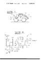
- FIG. 2 is a schematic representation, of a drive train for the winch unit of FIG. 1.
- FIG. 3 is a partially schematic representation, with parts being illustrated in section, of a control mechanism constructed to the present invention and adaptable for regulating operation of the winch unit of FIGS. 1 and 2.
- FIG. 4 is an enlarged fragmentary view of a portion of the control mechanism of FIG. 3 including a control lever together with first and second biasing means.
- control mechanism of the present invention is described below in particular detail relative to a winch unit of the type schematically represented in FIG. 2 and adapted for use on a log skidder as illustrated in FIG. 1.
- control mechanism may be employed for other applications as well, particularly applications wherein a single control lever is to be movable for regulating operation of first and second motor means at different rates of modulations.
- the control mechanism of the present invention is particularly adapted for operation of a towing or logging winch included within a log skidder vehicle of the type indicated at 10 in FIG. 1.
- the vehicle includes a prime mover or engine as illustrated in phantom at 12.
- it may include various implements such as a bulldozer blade 14 movably mounted upon one end of the vehicle.
- a winch unit 18 adapted for operation by the control mechanism of the present invention.
- winch unit 18 Construction and operation of the winch unit 18 is described in greater detail below having reference also to FIG. 2. However, it is generally noted that the winch unit 18 is operable in either a reeling-in or reeling-out mode of operation in order to permit operator control over a load (not shown) connected to a cable 20 associated with the winch unit 18 as described below.
- a power train indicated at 22 for the winch unit 18 includes a power input shaft 24 which may comprise a standard power take-off from the prime mover 12 for the vehicle in FIG. 1.
- the input shaft 24 is coupled by means of meshing transfer gears 26 and 28 with an input shaft 30 for a normally disengaged friction clutch 32.
- An output shaft 34 for the clutch 32 is coupled with a clutch output gear 36 which is also secured for rotation with a transfer gear 38.
- the clutch output gear 36 meshes with a brake gear 40, a normally engaged friction brake 42 being operable to secure the brake gear 40 against rotation.
- the components described above comprise an intermediate portion of the drive train.
- the normally disengaged clutch 32 permits driving operation of the gear components within the intermediate drive through the input shaft 24.
- the normally engaged brake 42 tends to be disengaged as the clutch 32 is engaged and conversely tends to be engaged as the clutch 32 is disengaged.
- the brake 42 normally serves to prevent rotation of the intermediate drive train or at least those components on the output side of the clutch 32 when the clutch is disengaged.
- the brake 42 is also adapted to be gradually disengaged without concurrent engagement of the clutch in order to permit reeling-out operation of the winch unit.
- An output portion of the winch drive train 22 includes a transfer gear 44 arranged in meshing engagement with the transfer gear 38.
- the gear 44 is mounted upon an input shaft 46 for a bevel gear assembly 48 having bevel gears 50 and 52.
- a winch drum shaft 54 provides an output for the bevel gear assembly 48 with a winch drum 56 being arranged for rotation upon the shaft 54 by means of bearings 58 and 60.
- the cable 20 is trained about the winch drum 56 to permit reeling-in or reeling-out of the cable according to rotation of the drum 56 under influence of the brake 42 and/or the clutch 32.
- the power train 22 also includes a normally engaged clutch 62 which may be separately disengaged to permit freewheeling of the winch drum 56.
- the free-wheeling clutch 62 is arranged for selective engagement between the drum 56 and its shaft 54.
- the brake 42 may be gradually disengaged in order to permit reeling-out of the cable 20 under an external load (not shown).
- the clutch 32 may be gradually engaged with concurrent gradual disengagement of the brake 42 in order to permit selective reeling-in of the cable 20.
- a control mechanism constructed according to the present invention for accomplishing these functions in a relatively simple manner is better illustrated in FIGS. 3 and 4.
- the winch drum 56 is generally illustrated together with the power train 22 which is hydraulically communicated with a control valve 70 by means of interconnected conduits 72 and 74.
- a control valve 70 by means of interconnected conduits 72 and 74.
- FIG. 2 it is sufficient for an understanding of the present invention to realize that as the valve or spool 70 is moved rightwardly, fluid under pressure from the source 76 is communicated to accomplish simultaneous engagement of the clutch 32 and disengagement of the brake 42. Accordingly, rightward movement of the valve 70 corresponds to reeling-in operation of the drum 56.
- the valve 70 is moved leftwardly, fluid is communicated to the brake 42 to cause its gradual disengagement without concurrent operation of the clutch 32. This, of course, corresponds to reeling-out operation of the cable 20 under the influence of an external load (not shown).
- control mechanism 80 includes a manually operable master cylinder unit 82 with a slave unit 84 being responsive to the master cylinder unit 82 for adjusting or positioning the control valve 70.
- the master cylinder unit 82 includes separate cylinders 86 and 88 including separate pistons 90 and 92 which are coupled in common to a single manual control element or lever 94.
- the slave unit 84 includes a first slave cylinder 96 which is in responsive communication by means of a conduit 98 with the master cylinder 86. Another slave cylinder 100 is in responsive communication by means of a conduit 102 with the other master cylinder 88.
- the slave unit 84 also includes a control lever 104 which is pivotably mounted at 106 and coupled at its opposite end to the valve 70.
- First and second biasing means 108 and 110 are respectively operated by the slave cylinders 96 and 100 in order to bias the control lever 104 and effect movement of the control valve 70 in opposite directions under different rates of modulation.
- the first biasing means 108 includes a lever 112 which is pivotably mounted at 114. A central portion of the lever 112 is pivotably connected to a piston 116 which is movable by the slave cylinder 96. The opposite end of the lever 112 rotatably supports a roller 118 which interacts with the lever 104 in a manner described below for accomplishing movement of the control valve 70 under a first rate of modulation.
- the second biasing means 110 includes a similar lever 122 which is pivotably mounted at 124 with a central portion of the lever being pivotably coupled with a piston 126 which is movable within the slave cylinder 100.
- a roller 128 is also mounted upon the opposite end of the lever 122.
- the first and second biasing means 108 and 110 are designed to provide different modulation rates for the valve 70. This feature of the invention could be accomplished in a number of ways such as by varying the effective lengths of the levers 112 and 122. However, the different rates of modulation are preferably accomplished by means of a common control element 130 arranged for pivotable movement with the lever 104 about its axis 106 upon interaction with either of the rollers 118 or 128.
- the different rates of modulation are accomplished through the configuration of separate surfaces 132 and 134 which are respectively arranged for interaction with the rollers 118 and 128. It may be seen in FIG. 4 that the rollers 118 and 128 are movable upon their levers 112 and 122 along arcs indicated respectively at 136 and 138. The angle of intersection for each of the surfaces 132 and 134 with the respective arcs 136 and 138 determines the rate of movement for the control lever 104 under the influence of either roller 118 or 128.
- the surface 132 is arranged at a relatively sharp angle to the arc 136 so that as the slave cylinder 96 is actuated by the master cylinder 86 and the piston 116 urges the lever 112 toward the right, the roller 118 interacts with the surface 132 to cause relatively rapid movement of the control lever 104 (rightwardly) which results in a relatively high rate of modulation for the valve 70.
- the surface 134 is arranged at a relatively slight angle with the arc 138. Accordingly, as the slave cylinder 100 is actuated by the master cylinder 88 and its piston 126 and lever 122 are urged rightwardly, interaction of the roller 128 with the surface 134 causes movement of the control lever 104 (leftwardly) at a relatively slow rate which results in modulation of the control valve 70 likewise at a relatively low rate.
- a powertrain, as particularly illustrated in FIG. 2 for operating a winch, is also described in greater detail within an application filed Feb. 21, 1973, application Ser. No. 334,354, now abandoned assigned to the assignee of the present invention.
- the control mechanism of this invention may also be employed in other powertrains, for example, such as the reversible towing winch of U.S. Pat. No. 3,729,171 also assigned to the assignee of the present invention.
Landscapes
- Engineering & Computer Science (AREA)
- Mechanical Engineering (AREA)
- Chemical & Material Sciences (AREA)
- Combustion & Propulsion (AREA)
- Transportation (AREA)
- Mechanical Control Devices (AREA)
Priority Applications (5)
| Application Number | Priority Date | Filing Date | Title |
|---|---|---|---|
| US05/543,579 US3990552A (en) | 1975-01-23 | 1975-01-23 | Variably biased control mechanism |
| CA235,982A CA1027016A (en) | 1975-01-23 | 1975-09-22 | Variably biased control mechanism |
| JP50120844A JPS5848477B2 (ja) | 1975-01-23 | 1975-10-08 | エキアツウインチニタイスルセイギヨキコウ |
| BR7507990*A BR7507990A (pt) | 1975-01-23 | 1975-12-02 | Mecanismo de controle |
| US05/707,161 US4074613A (en) | 1975-01-23 | 1976-07-21 | Variably biased control mechanism |
Applications Claiming Priority (1)
| Application Number | Priority Date | Filing Date | Title |
|---|---|---|---|
| US05/543,579 US3990552A (en) | 1975-01-23 | 1975-01-23 | Variably biased control mechanism |
Related Child Applications (1)
| Application Number | Title | Priority Date | Filing Date |
|---|---|---|---|
| US05/707,161 Division US4074613A (en) | 1975-01-23 | 1976-07-21 | Variably biased control mechanism |
Publications (1)
| Publication Number | Publication Date |
|---|---|
| US3990552A true US3990552A (en) | 1976-11-09 |
Family
ID=24168623
Family Applications (2)
| Application Number | Title | Priority Date | Filing Date |
|---|---|---|---|
| US05/543,579 Expired - Lifetime US3990552A (en) | 1975-01-23 | 1975-01-23 | Variably biased control mechanism |
| US05/707,161 Expired - Lifetime US4074613A (en) | 1975-01-23 | 1976-07-21 | Variably biased control mechanism |
Family Applications After (1)
| Application Number | Title | Priority Date | Filing Date |
|---|---|---|---|
| US05/707,161 Expired - Lifetime US4074613A (en) | 1975-01-23 | 1976-07-21 | Variably biased control mechanism |
Country Status (4)
| Country | Link |
|---|---|
| US (2) | US3990552A (enExample) |
| JP (1) | JPS5848477B2 (enExample) |
| BR (1) | BR7507990A (enExample) |
| CA (1) | CA1027016A (enExample) |
Cited By (3)
| Publication number | Priority date | Publication date | Assignee | Title |
|---|---|---|---|---|
| EP0013475A1 (en) * | 1978-12-07 | 1980-07-23 | Caterpillar Tractor Co. | Apparatus for supplying fluid to a plurality of mechanisms |
| US4448398A (en) * | 1982-03-01 | 1984-05-15 | Garlock Equipment Company | Winch control system |
| US20110037040A1 (en) * | 2009-08-13 | 2011-02-17 | Hess Daniel L | Fluid shear actuated hoist brake |
Families Citing this family (3)
| Publication number | Priority date | Publication date | Assignee | Title |
|---|---|---|---|---|
| JPS61181775U (enExample) * | 1985-05-01 | 1986-11-13 | ||
| JPS6258679U (enExample) * | 1985-10-02 | 1987-04-11 | ||
| US6871833B1 (en) * | 1999-06-30 | 2005-03-29 | Seagate Technology Llc | Disc drive shocking station with high speed spool valve actuation |
Citations (6)
| Publication number | Priority date | Publication date | Assignee | Title |
|---|---|---|---|---|
| US2279597A (en) * | 1939-07-14 | 1942-04-14 | Selmer Johan Fredrik | Controlling means for hoists and winches |
| US2543649A (en) * | 1950-07-12 | 1951-02-27 | Gen Electric | Linkage for hydraulic actuators |
| US2725890A (en) * | 1950-03-22 | 1955-12-06 | Borg Warner | Hydraulic power control system |
| US3124970A (en) * | 1964-03-17 | Walker | ||
| US3144107A (en) * | 1955-07-25 | 1964-08-11 | Jered Ind Inc | Multiple speed transmission |
| US3841608A (en) * | 1973-02-21 | 1974-10-15 | Caterpillar Tractor Co | Modulating control valve for hydraulically operated winch |
Family Cites Families (7)
| Publication number | Priority date | Publication date | Assignee | Title |
|---|---|---|---|---|
| US44071A (en) * | 1864-09-06 | Improvement in valve-gear for steam-engines | ||
| US415671A (en) * | 1889-11-19 | harris | ||
| US287877A (en) * | 1883-11-06 | Valve-gear | ||
| US26301A (en) * | 1859-11-29 | David stoddart | ||
| CA706196A (en) * | 1965-03-23 | Applied Power Industries | Hydraulic control system | |
| US1092359A (en) * | 1913-09-18 | 1914-04-07 | Metallpapier Bronzefarben Blattmetallwerke Ag | Control device for sheet-separators. |
| US3055225A (en) * | 1960-02-26 | 1962-09-25 | United Aircraft Corp | Auxiliary control lever |
-
1975
- 1975-01-23 US US05/543,579 patent/US3990552A/en not_active Expired - Lifetime
- 1975-09-22 CA CA235,982A patent/CA1027016A/en not_active Expired
- 1975-10-08 JP JP50120844A patent/JPS5848477B2/ja not_active Expired
- 1975-12-02 BR BR7507990*A patent/BR7507990A/pt unknown
-
1976
- 1976-07-21 US US05/707,161 patent/US4074613A/en not_active Expired - Lifetime
Patent Citations (6)
| Publication number | Priority date | Publication date | Assignee | Title |
|---|---|---|---|---|
| US3124970A (en) * | 1964-03-17 | Walker | ||
| US2279597A (en) * | 1939-07-14 | 1942-04-14 | Selmer Johan Fredrik | Controlling means for hoists and winches |
| US2725890A (en) * | 1950-03-22 | 1955-12-06 | Borg Warner | Hydraulic power control system |
| US2543649A (en) * | 1950-07-12 | 1951-02-27 | Gen Electric | Linkage for hydraulic actuators |
| US3144107A (en) * | 1955-07-25 | 1964-08-11 | Jered Ind Inc | Multiple speed transmission |
| US3841608A (en) * | 1973-02-21 | 1974-10-15 | Caterpillar Tractor Co | Modulating control valve for hydraulically operated winch |
Cited By (4)
| Publication number | Priority date | Publication date | Assignee | Title |
|---|---|---|---|---|
| EP0013475A1 (en) * | 1978-12-07 | 1980-07-23 | Caterpillar Tractor Co. | Apparatus for supplying fluid to a plurality of mechanisms |
| US4448398A (en) * | 1982-03-01 | 1984-05-15 | Garlock Equipment Company | Winch control system |
| US20110037040A1 (en) * | 2009-08-13 | 2011-02-17 | Hess Daniel L | Fluid shear actuated hoist brake |
| US8246010B2 (en) * | 2009-08-13 | 2012-08-21 | Hess Daniel L | Fluid shear actuated hoist brake |
Also Published As
| Publication number | Publication date |
|---|---|
| US4074613A (en) | 1978-02-21 |
| JPS5187241A (enExample) | 1976-07-30 |
| CA1027016A (en) | 1978-02-28 |
| JPS5848477B2 (ja) | 1983-10-28 |
| BR7507990A (pt) | 1976-08-24 |
Similar Documents
| Publication | Publication Date | Title |
|---|---|---|
| US4093034A (en) | Vehicle supported winch | |
| US3550735A (en) | Fluid pressure reversing clutches and brake for winch | |
| US4588057A (en) | Loaded hydraulically actuatable piston and controls system therefor | |
| US3990552A (en) | Variably biased control mechanism | |
| US3841608A (en) | Modulating control valve for hydraulically operated winch | |
| US3128861A (en) | trondsen | |
| US3371543A (en) | Engine power takeoff drive | |
| US4004779A (en) | Winch and fluid control system therefor | |
| US4042215A (en) | Winch control mechanism | |
| US4739850A (en) | Walking operator type agricultural machine having transmission system with disk type frictional stepless change speed apparatus | |
| GB1349924A (en) | Reversible winch | |
| US3991787A (en) | Modulation control valve for hydraulically operated winch | |
| US3702648A (en) | Brake release reversing transmission clutches | |
| US4024935A (en) | Power transmission in double-drum winch | |
| US4014419A (en) | Sequential operator for clutch and brake | |
| US3988008A (en) | Power lowering system | |
| DE1951024C2 (de) | Lastkran | |
| GB1568903A (en) | Vehicle with dual braking systems | |
| US4076219A (en) | Fluid pressure-controlled winch mechanism | |
| US3059504A (en) | Variable speed and torque transmission | |
| US3840099A (en) | Forward-reverse clutch control apparatus | |
| US4069884A (en) | Self-propelled drive mechanism | |
| US4022432A (en) | Power transmission in double-drum winch | |
| US2857137A (en) | Winch | |
| US3231241A (en) | Steam or hydraulically operable winch |
Legal Events
| Date | Code | Title | Description |
|---|---|---|---|
| AS | Assignment |
Owner name: CATERPILLAR INC., 100 N.E. ADAMS STREET, PEORIA, I Free format text: ASSIGNMENT OF ASSIGNORS INTEREST.;ASSIGNOR:CATERPILLAR TRACTOR CO., A CORP. OF CALIF.;REEL/FRAME:004669/0905 Effective date: 19860515 Owner name: CATERPILLAR INC., A CORP. OF DE.,ILLINOIS Free format text: ASSIGNMENT OF ASSIGNORS INTEREST;ASSIGNOR:CATERPILLAR TRACTOR CO., A CORP. OF CALIF.;REEL/FRAME:004669/0905 Effective date: 19860515 |