US3973363A - Inflatable structures - Google Patents
Inflatable structures Download PDFInfo
- Publication number
- US3973363A US3973363A US05/420,709 US42070973A US3973363A US 3973363 A US3973363 A US 3973363A US 42070973 A US42070973 A US 42070973A US 3973363 A US3973363 A US 3973363A
- Authority
- US
- United States
- Prior art keywords
- inflatable
- enclosures
- cells
- layers
- spheres
- Prior art date
- Legal status (The legal status is an assumption and is not a legal conclusion. Google has not performed a legal analysis and makes no representation as to the accuracy of the status listed.)
- Expired - Lifetime
Links
- 239000000463 material Substances 0.000 claims abstract description 19
- 210000004027 cell Anatomy 0.000 description 42
- 238000010276 construction Methods 0.000 description 6
- 238000005192 partition Methods 0.000 description 3
- 230000015572 biosynthetic process Effects 0.000 description 2
- 230000006355 external stress Effects 0.000 description 2
- 238000005755 formation reaction Methods 0.000 description 2
- 238000000034 method Methods 0.000 description 2
- 230000003466 anti-cipated effect Effects 0.000 description 1
- 210000002421 cell wall Anatomy 0.000 description 1
- 230000001413 cellular effect Effects 0.000 description 1
- 230000007423 decrease Effects 0.000 description 1
- 230000003247 decreasing effect Effects 0.000 description 1
- 230000000694 effects Effects 0.000 description 1
- 230000001747 exhibiting effect Effects 0.000 description 1
- 239000007789 gas Substances 0.000 description 1
- 230000005484 gravity Effects 0.000 description 1
- 239000001307 helium Substances 0.000 description 1
- 229910052734 helium Inorganic materials 0.000 description 1
- SWQJXJOGLNCZEY-UHFFFAOYSA-N helium atom Chemical compound [He] SWQJXJOGLNCZEY-UHFFFAOYSA-N 0.000 description 1
- 229920003023 plastic Polymers 0.000 description 1
- 239000004033 plastic Substances 0.000 description 1
- 230000035882 stress Effects 0.000 description 1
- 238000004078 waterproofing Methods 0.000 description 1
Images


Classifications
-
- E—FIXED CONSTRUCTIONS
- E04—BUILDING
- E04H—BUILDINGS OR LIKE STRUCTURES FOR PARTICULAR PURPOSES; SWIMMING OR SPLASH BATHS OR POOLS; MASTS; FENCING; TENTS OR CANOPIES, IN GENERAL
- E04H15/00—Tents or canopies, in general
- E04H15/20—Tents or canopies, in general inflatable, e.g. shaped, strengthened or supported by fluid pressure
- E04H2015/202—Tents or canopies, in general inflatable, e.g. shaped, strengthened or supported by fluid pressure with inflatable panels, without inflatable tubular framework
- E04H2015/204—Tents or canopies, in general inflatable, e.g. shaped, strengthened or supported by fluid pressure with inflatable panels, without inflatable tubular framework made from contiguous inflatable tubes
Definitions
- inflatable structures an assembly of parts, of which at least some are inflatable, joined one to another in such a fashion that the assembly assumes a specific rigid form after inflation of the inflatable parts.
- FIGS. 1, 2 and 3 show in schematic sectional representation the inflatable structures known at the moment.
- One kind of known inflatable structure was made up of an assembly of inflatable cells coupled together.
- Another type of structure was formed of two layers of woven material linked together by partition walls, also of woven material, which thus defined chambers into which were inserted inflatable bladders which were not fixed to the said layers of woven material and whose purpose was simply to maintain these latter in spaced relationship.
- Another form of prior art structure was made up of two layers of a flexible, gas-tight, woven material or sheet, linked together by partition walls also of a gas-tight material so as to define chambers which were subsequently inflated.
- One object of the invention is an inflatable structure whose rigidity, after inflation of the inflatable parts, may be of any desired magnitude.
- Another object of the invention is an inflatable structure which does not exert on its supports any strains other than those due to its weight.
- a further object of the invention is an inflatable structure which may be made in a large variety of sizes.
- Yet another object of the invention is an inflatable structure which may be used to form shelters or parts of shelters, which may or may not be collapsible, or to form objects intended to carry loads, such as bridges and, in a general way, inflatable constructions and articles of many different kinds.
- Inflatable structures according to the invention comprise two rectilinear flexible sheets, separated one from the other, and inflatable enclosures situated in the space separating the two sheets, the said inflatable enclosures being fixed to each sheet and being joined together so that, on inflation, they mutually support one another and apply tension to the members forming the two sheets.
- the inflatable enclosures are enclosures formed from a flexible sheet or woven material, impervious to the inflating medium.
- enclosures can be used which are cellular in nature and may be rectilinear or curvilinear: their section may be constant or vary along their length. Enclosures may also be used which are spheres or cylinders with spherical dome-like ends.
- the rectilinear members forming the sheets between which the enclosures are positioned and to which they are fixed must have sufficient mechanical strength to bear the strain imposed by the inflation of the enclosures. This may be incorporated by a layer or strip of woven material or by wires or cords.
- the attachment of the rectilinear members forming the two sheets to the enclosures may be effected by conventional means not per se forming part of the invention, for example by bonding.
- FIGS. 1, 2 and 3 show schematically sections through various prior art inflatable structures
- FIG. 4 shows schematically a cross-section through a part of a first embodiment of inflatable structure according to the invention
- FIG. 5 shows schematically a cross-section through part of another embodiment of structure
- FIG. 6 shows schematically a cross-section through a third embodiment of structure
- FIG. 7 shows a cross-section of the structure of FIG. 6 during erection
- FIG. 8 shows schematically a cross-section of another structure according to the invention, used as the collapsible part of a shelter
- FIG. 9 shows a section of the structure of FIG. 8 in a partly open state
- FIG. 10 shows a perspective view of a structure of the invention
- FIG. 11 shows a perspective view of another embodiment of structure according to the invention.
- FIG. 12 shows a view from above of another embodiment
- FIG. 13 shows a cross-section of the structure of FIG. 12 along the line XIII--XIII thereof
- FIG. 14 shows a view from above of another embodiment
- FIG. 15 shows a view from above of another embodiment
- FIG. 16 shows a view from above of a part of a further embodiment of the invention.
- FIG. 1 shows a first example of an inflatable structure of the prior art, which comprises a plurality of inflatable cells 1 that are coupled together.
- FIG. 2 shows another example of a prior art construction which is formed of two layers 2 and 3 of a woven material which are linked together by partition walls 4 which also are of woven material, and these walls thus define chambers 5 serving as location means for inflatable bladders 6 inserted therein.
- These bladders 6 are not fixed to the layers 2 and 3 and their purpose is simply to maintain the layers 2 and 3 in spaced relationship.
- FIGS. 4 and 5 show a flat, inflatable structure; it may, for example, be used as a cover by being placed on the exterior walls of a building.
- This structure is made up as shown of rectilinear, inflatable cells, 10a, 10b, 10c . . . which are attached to the sheet 11 at A 1 , B 1 , C 1 and to sheet 12 at A 2 , B 2 , C 2 .
- the inflatable cells are made of a gas-tight rubberised material and sheets 11 and 12 are of a woven material of which the warp runs perpendicularly to the axis of the cells.
- the sheets 11 and 12 could also be formed by cables, mutually parallel and perpendicular to the axis of the cells; in this case, a light and water-proof sheet, made, for example, of a plastics material, could be attached to the upper sheet 11 for water-proofing purposes.
- Sheets 11 and 12 are attached to the cells 10 by bonding but they could also be attached by some other conventional means, not forming part of the invention. Since the structure is flat, the lengths d' at A' B', B' C', C' . . . and the lengths d 2 at A 2 B 2 , B 2 C 2 , C 2 . . . are all of equal size.
- the circumference of the cell walls is sufficiently great, taking into account the size of lengths d 1 or d 2 that, after inflation, cells 10 bear on and support one another. (This condition is fulfilled as soon as the circumference of the boundary walls exceeds the value ⁇ x d 1 ).
- the cells are inflated to the same or to a very similar pressure so that their meeting faces, which are formed by lines a 1 a 2 , b 1 b 2 , c 1 c 2 , of FIG. 4 are plane.
- cells 10 When they are deflated, cells 10 are collapsed and the sheets 11 and 12, no longer being under tension, are in close proximity.
- sheets 11 and 12 move apart and each cell 10, taking a purchase on the adjoining cell, places the portion of the sheet situated between the attachment of the cell to the sheet and the attachment of the adjoining cell to the sheet, under tension.
- the inflatable structures according to the invention by reason of having two sheets under tension, separated from each other, are extremely rigid and little subject to deformation as a result of external stresses such as those due to gravity or the action of the wind. This rigidity increases as sheets 11 and 12 are more strongly tensioned.
- the tension of the sheets varies both as a function of the pressure inside the cells and of the length of the portions a 1 a 2 , b 1 b 2 , c 1 c 2 . . . it may thus be set to the desired amount by varying the pressure inside the cells by giving to the cells a circumference such that the length of said portions is greater or smaller.
- cells 10 can be as long as desired which means that the range of sizes of the inflatable structures in the invention is theoretically unlimited.
- the inflatable structures self-stabilising (i.e. they do not distort of themselves in the absence of external stresses), once inflation is completed, but also, during inflation, the parts already inflated are themselves self-stabilising (and similarly during deflation).
- This self-stabilising property has the additional result that any bases or foundations used, which have only to bear the strains due to the weight of the structures, which are extremely light, are of minor importance.
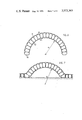
- the structure shown in FIG. 6 is formed similarly to those in FIGS. 4 and 5 but lengths d 1 and d 2 , instead of being equal, are different, which gives the structure a curvilinear shape.
- the lines a 1 a 2 , b 1 b 2 , c 1 c 2 , shown in FIGS. 4 and 5 are decreased to zero in the arrangement of FIG. 6 meeting at a point which is the centre of the circle of curvature of which the radius depends both on the ratio d 1 /d 2 and on the distance separating the two sheets 11 and 12 which itself depends on the circumference of the inflatable cells.
- FIG. 6 shows in fact a cross-section through a shelter such as a shed, having the shape of a segment of a cylinder.
- This shelter is formed by an inflatable structure similar to that in FIG. 5; cells 10 place the portions of the sheets 11 and 12 extending between two adjoining cells under tension; lengths d 1 and d 2 are unequal.
- This construction may be of very large dimensions and, on account of its small weight and of the absence of stresses not vertical to the ground, it may be erected on surfaces of loose consistency without the need for considerable foundation work.
- FIG. 7 shows the ease of erection of such a construction, which is, and remains, self-stabilising during inflation of the cells.
- the central cells are inflated first; due to this inflation, the central portion of the structure takes up the curve described by a radius R equal to that in the construction in FIG. 6 and the central portion, inflated, being self-stabilising, there is no need to use additional means of support or guidance; the process is continued by inflating the cells immediately adjacent to the portion already inflated and so on; when the two end cells are inflated, the whole of the structure has been formed and is ready for use.
- the erection of structures according to the invention is extremely simple. Similarly, to collapse such a structure, it is merely necessary to deflate the end cell then the immediately adjacent cells and so on.
- FIGS. 8 and 9 constitute the collapsible portion of a shelter.
- Cells 10 form an arc and their cross-section decreases from the centre towards the ends; in addition, the distances d 1 and d 2 between the attachments of two adjacent cells to the sheets 11 and 12 are unequal as in the case of FIG. 6; thus, a dome-shaped structure is obtained.
- this inflatable dome rests on another part 13 of the shelter; this part 13 is built of masonry and includes a projecting portion 13a against the face 13b of which the inflatable dome bears.
- the inflatable dome may be totally or partially collapsed by deflating the lower cells as at 10a in FIG. 9 which Figure shows the shelter of FIG. 8 with the dome partially collapsed.
- each cell 10a When the lower cells 10a are deflated, the corresponding portions of the dome weaken and fold up and the upper cell 10b moves away from part 13a; each cell, still inflated, moves around an axis passing through the centre 0 of the circle of curvature each time one of the lower cells is deflated, which brings about the opening of the dome.
- the portion of the dome still inflated is self-stabilising which allows the dome to be left partially open, if desired.
- the cells are straight-sided and arranged parallel to the axis of the cylinder, i.e., parallel to the faces on which it rests.
- the curvature results from the fact that the distances between the attachments of two adjacent cells to the upper and lower sheet (i.e. portions d 1 and d 2 of FIG. 4) are unequal.
- the structure in FIG. 11 has the same shape as that of FIG. 10 but the arch-shaped cells are perpendicular to the axis of the cylinder.
- the equivalent to distances d 1 and d 2 are equal, the curvature of the structure resulting from the shape of the cells.
- the enclosures are formed by laterally flattened tubular cells, i.e. cylindrical formations.
- the enclosures may also be spheres or cylinders whose ends terminate in spherical domes; inflatable enclosures of this latter kind will hereinafter be called “spherical enclosures ⁇ or “inflatable spherical enclosures”.
- FIGS. 12, 13 The application of the invention to the use of inflatable spherical enclosures, will be explained by FIGS. 12, 13 in the case of inflatable structures assumed to comprise only seven inflatable enclosures.
- the inflatable enclosures are spheres linked together.
- Two adjacent spheres are attached to two straight and flexible members 14 and 16, situated diametrically oppositely of the spheres, tangential to one another and parallel to the plane of the centres of the spheres.
- the flexible members 14 and 16 are of a length at least slightly smaller than the radius of the spheres.
- the spheres press against one another and tense members 14 and 16.
- the members 14 and 16 After inflation of the spheres, the members 14 and 16 form two layers, each of which is a trellis or a mesh configuration, the members of which are under tension.
- Members 14 and 16 may be formed by an assembly of parallel wires or cords; they may also be made up by strips either of woven material or of a material having sufficient mechanical strength.
- a sheet or a woven material having no discontinuities may be attached thereto, provided that it possesses sufficient mechanical strength in the direction in which it will be under tension due to the effect of the inflation of the spheres.
- inflated enclosures in the form of a cylinder the ends of which are formed by spherical domes, may be used; these enclosures, which behave in all respects as spheres, are easier to construct than spheres when the distance separating members 14 and 16 is relatively large, for example more than 50 cm.
- FIG. 12 shows the mesh of a trellis, the members of which meet at an angle of 60°.
- FIG. 14 shows another possible method of laying out the spheres; in this case sphere centres are placed at the corners of squares, which brings about the formation of a trellis, the members of which meet at an angle 90°.
- FIGS. 12 to 16 show the possible variations of trellis pattern which can be produced; to form structures extending over a greater area, it is merely necessary to join up several patterns, identical or different, by laying out the spheres in the appropriate positions.
- inflatable structures according to the invention may be produced having the shape of a dome or exhibiting multiple and various curvatures, more easily than by using laterally flattened tubes; in fact, it is sufficient to vary the length of members 14 and 16 if spherical enclosures are being used, while arch-shaped cells must be made if it is desired to produce structures, which like the domes, are not in the form of a segment of a cylinder or a succession of segments of cylinder.
Landscapes
- Engineering & Computer Science (AREA)
- Architecture (AREA)
- Physics & Mathematics (AREA)
- Fluid Mechanics (AREA)
- Civil Engineering (AREA)
- Structural Engineering (AREA)
- Tents Or Canopies (AREA)
Abstract
This invention relates to inflatable structures, that is to say, to an assembly of parts of which some at least are inflatable and joined one to another in such a fashion that the assembly assumes a specific rigid form after the inflation of the inflatable parts. In accordance with the invention, the inflatable structure comprises a plurality of inflatable enclosures joined together with pressure contact and these inflatable enclosures are located between two layers of flexible material to which they are fixed, placing the said layers under tension. Various shapes are described for the inflatable enclosures and the points of attachment of these enclosures to the upper and lower flexible layers may be the same where it is required to make a flat structure, or different where it is desired to make a curvilinear structure.
Description
This application is a continuation-in-part from application Ser. No. 249,278 filed May 1, 1972.
The present invention relates to inflatable structures. By inflatable structures is meant an assembly of parts, of which at least some are inflatable, joined one to another in such a fashion that the assembly assumes a specific rigid form after inflation of the inflatable parts.
Inflatable structures in the sense of the foregoing definition have been known for a long time. Thus, U.S. Pat. No. 511,472 dating from 1893 describes such structures; since then many improved inflatable structures have been proposed and described, but, in fact, none has enjoyed the success anticipated. This is attributable to the fact that, up to now, all have suffered from the same major drawback of lack of rigidity.
FIGS. 1, 2 and 3 show in schematic sectional representation the inflatable structures known at the moment.
One kind of known inflatable structure was made up of an assembly of inflatable cells coupled together.
Another type of structure was formed of two layers of woven material linked together by partition walls, also of woven material, which thus defined chambers into which were inserted inflatable bladders which were not fixed to the said layers of woven material and whose purpose was simply to maintain these latter in spaced relationship.
Another form of prior art structure was made up of two layers of a flexible, gas-tight, woven material or sheet, linked together by partition walls also of a gas-tight material so as to define chambers which were subsequently inflated.
In all the above described prior art structures, the same principle was employed, namely to use the pressure of the inflating medium simply to hold two walls apart.
All these structures lack rigidity; in order that they may retain their shape, braces or rigid attachment members had to be used, or certain portions had to be inflated with a lighter-than-air gas such as helium. In this connection, U.S. Pat. No. 511,472 shows structures in which the means used do not allow the desired rigidity to be achieved. It can thus be said that, since 1893 at least, efforts have been made to produce inflatable structures which should be extremely rigid after inflation, but, up to now, no simple expedient has been found which enables this rigidity to be conferred on them.
One object of the invention is an inflatable structure whose rigidity, after inflation of the inflatable parts, may be of any desired magnitude.
Another object of the invention is an inflatable structure which does not exert on its supports any strains other than those due to its weight. A further object of the invention is an inflatable structure which may be made in a large variety of sizes.
Yet another object of the invention is an inflatable structure which may be used to form shelters or parts of shelters, which may or may not be collapsible, or to form objects intended to carry loads, such as bridges and, in a general way, inflatable constructions and articles of many different kinds.
Inflatable structures according to the invention comprise two rectilinear flexible sheets, separated one from the other, and inflatable enclosures situated in the space separating the two sheets, the said inflatable enclosures being fixed to each sheet and being joined together so that, on inflation, they mutually support one another and apply tension to the members forming the two sheets.
The inflatable enclosures are enclosures formed from a flexible sheet or woven material, impervious to the inflating medium. As will be seen below, enclosures can be used which are cellular in nature and may be rectilinear or curvilinear: their section may be constant or vary along their length. Enclosures may also be used which are spheres or cylinders with spherical dome-like ends.
The rectilinear members forming the sheets between which the enclosures are positioned and to which they are fixed must have sufficient mechanical strength to bear the strain imposed by the inflation of the enclosures. This may be incorporated by a layer or strip of woven material or by wires or cords.
The attachment of the rectilinear members forming the two sheets to the enclosures may be effected by conventional means not per se forming part of the invention, for example by bonding.
In order that the invention may be more clearly understood, reference will now be made to the accompanying drawings which, firstly, show some examples of prior art structures and then certain embodiments of the invention by way of example, and in which:
FIGS. 1, 2 and 3 show schematically sections through various prior art inflatable structures,
FIG. 4 shows schematically a cross-section through a part of a first embodiment of inflatable structure according to the invention,
FIG. 5 shows schematically a cross-section through part of another embodiment of structure;
FIG. 6 shows schematically a cross-section through a third embodiment of structure,
FIG. 7 shows a cross-section of the structure of FIG. 6 during erection,
FIG. 8 shows schematically a cross-section of another structure according to the invention, used as the collapsible part of a shelter,
FIG. 9 shows a section of the structure of FIG. 8 in a partly open state,
FIG. 10 shows a perspective view of a structure of the invention,
FIG. 11 shows a perspective view of another embodiment of structure according to the invention,
FIG. 12 shows a view from above of another embodiment,
FIG. 13 shows a cross-section of the structure of FIG. 12 along the line XIII--XIII thereof,
FIG. 14 shows a view from above of another embodiment,
FIG. 15 shows a view from above of another embodiment, and
FIG. 16 shows a view from above of a part of a further embodiment of the invention.
Referring now to the drawings, FIG. 1 shows a first example of an inflatable structure of the prior art, which comprises a plurality of inflatable cells 1 that are coupled together.
FIG. 2 shows another example of a prior art construction which is formed of two layers 2 and 3 of a woven material which are linked together by partition walls 4 which also are of woven material, and these walls thus define chambers 5 serving as location means for inflatable bladders 6 inserted therein. These bladders 6 are not fixed to the layers 2 and 3 and their purpose is simply to maintain the layers 2 and 3 in spaced relationship.
FIGS. 4 and 5 show a flat, inflatable structure; it may, for example, be used as a cover by being placed on the exterior walls of a building.
This structure is made up as shown of rectilinear, inflatable cells, 10a, 10b, 10c . . . which are attached to the sheet 11 at A1, B1, C1 and to sheet 12 at A2, B2, C2.
In this embodiment, the inflatable cells are made of a gas-tight rubberised material and sheets 11 and 12 are of a woven material of which the warp runs perpendicularly to the axis of the cells. Instead of being made up of a woven material, the sheets 11 and 12 could also be formed by cables, mutually parallel and perpendicular to the axis of the cells; in this case, a light and water-proof sheet, made, for example, of a plastics material, could be attached to the upper sheet 11 for water-proofing purposes.
The circumference of the cell walls is sufficiently great, taking into account the size of lengths d1 or d2 that, after inflation, cells 10 bear on and support one another. (This condition is fulfilled as soon as the circumference of the boundary walls exceeds the value μ x d1). The cells are inflated to the same or to a very similar pressure so that their meeting faces, which are formed by lines a1 a2, b1 b2, c1 c2, of FIG. 4 are plane.
When they are deflated, cells 10 are collapsed and the sheets 11 and 12, no longer being under tension, are in close proximity. When the cells are inflated, sheets 11 and 12 move apart and each cell 10, taking a purchase on the adjoining cell, places the portion of the sheet situated between the attachment of the cell to the sheet and the attachment of the adjoining cell to the sheet, under tension.
Thus, successive portions A1 B1, B1 C1, C1 . . . A2 B2, B2 C2, C2 . . . of the two sheets 11, 12, mutually separated by cells 10, are all placed under tension.
The inflatable structures according to the invention, by reason of having two sheets under tension, separated from each other, are extremely rigid and little subject to deformation as a result of external stresses such as those due to gravity or the action of the wind. This rigidity increases as sheets 11 and 12 are more strongly tensioned. The tension of the sheets varies both as a function of the pressure inside the cells and of the length of the portions a1 a2, b1 b2, c1 c2 . . . it may thus be set to the desired amount by varying the pressure inside the cells by giving to the cells a circumference such that the length of said portions is greater or smaller.
The tension of each section of sheet, such as A1 B1 or A2 B2 being in each transverse section exactly balanced, cells 10 can be as long as desired which means that the range of sizes of the inflatable structures in the invention is theoretically unlimited.
Not only are the inflatable structures self-stabilising (i.e. they do not distort of themselves in the absence of external stresses), once inflation is completed, but also, during inflation, the parts already inflated are themselves self-stabilising (and similarly during deflation). This has the result that, to erect or collapse the structures, it is not necessary to use additional means to support or guide them and that, with advantage, they may be used to produce constructions which are wholly or partly collapsible. This self-stabilising property has the additional result that any bases or foundations used, which have only to bear the strains due to the weight of the structures, which are extremely light, are of minor importance.
The structure shown in FIG. 6 is formed similarly to those in FIGS. 4 and 5 but lengths d1 and d2, instead of being equal, are different, which gives the structure a curvilinear shape. The lines a1 a2, b1 b2, c1 c2, shown in FIGS. 4 and 5 are decreased to zero in the arrangement of FIG. 6 meeting at a point which is the centre of the circle of curvature of which the radius depends both on the ratio d1 /d2 and on the distance separating the two sheets 11 and 12 which itself depends on the circumference of the inflatable cells.
FIG. 6 shows in fact a cross-section through a shelter such as a shed, having the shape of a segment of a cylinder.
This shelter is formed by an inflatable structure similar to that in FIG. 5; cells 10 place the portions of the sheets 11 and 12 extending between two adjoining cells under tension; lengths d1 and d2 are unequal.
This construction may be of very large dimensions and, on account of its small weight and of the absence of stresses not vertical to the ground, it may be erected on surfaces of loose consistency without the need for considerable foundation work.
FIG. 7 shows the ease of erection of such a construction, which is, and remains, self-stabilising during inflation of the cells. The central cells are inflated first; due to this inflation, the central portion of the structure takes up the curve described by a radius R equal to that in the construction in FIG. 6 and the central portion, inflated, being self-stabilising, there is no need to use additional means of support or guidance; the process is continued by inflating the cells immediately adjacent to the portion already inflated and so on; when the two end cells are inflated, the whole of the structure has been formed and is ready for use. From this example, it can be seen that the erection of structures according to the invention is extremely simple. Similarly, to collapse such a structure, it is merely necessary to deflate the end cell then the immediately adjacent cells and so on.
The inflatable structure in FIGS. 8 and 9 constitute the collapsible portion of a shelter.
In the embodiment, this inflatable dome rests on another part 13 of the shelter; this part 13 is built of masonry and includes a projecting portion 13a against the face 13b of which the inflatable dome bears.
The inflatable dome may be totally or partially collapsed by deflating the lower cells as at 10a in FIG. 9 which Figure shows the shelter of FIG. 8 with the dome partially collapsed.
When the lower cells 10a are deflated, the corresponding portions of the dome weaken and fold up and the upper cell 10b moves away from part 13a; each cell, still inflated, moves around an axis passing through the centre 0 of the circle of curvature each time one of the lower cells is deflated, which brings about the opening of the dome. As has been explained above, the portion of the dome still inflated is self-stabilising which allows the dome to be left partially open, if desired.
In the structure in FIG. 10, which is a segment of cylinder, the cells are straight-sided and arranged parallel to the axis of the cylinder, i.e., parallel to the faces on which it rests. Here the curvature results from the fact that the distances between the attachments of two adjacent cells to the upper and lower sheet (i.e. portions d1 and d2 of FIG. 4) are unequal.
The structure in FIG. 11 has the same shape as that of FIG. 10 but the arch-shaped cells are perpendicular to the axis of the cylinder. Here the equivalent to distances d1 and d2 are equal, the curvature of the structure resulting from the shape of the cells.
In the inflatable structures described up to this point, the enclosures are formed by laterally flattened tubular cells, i.e. cylindrical formations. However, as referred to above, the enclosures may also be spheres or cylinders whose ends terminate in spherical domes; inflatable enclosures of this latter kind will hereinafter be called "spherical enclosures⃡ or "inflatable spherical enclosures".
The application of the invention to the use of inflatable spherical enclosures, will be explained by FIGS. 12, 13 in the case of inflatable structures assumed to comprise only seven inflatable enclosures.
In the case of FIGS. 12 and 13 the inflatable enclosures are spheres linked together. Two adjacent spheres are attached to two straight and flexible members 14 and 16, situated diametrically oppositely of the spheres, tangential to one another and parallel to the plane of the centres of the spheres. There are thus twelve flexible members 14 and twelve flexible members 16, each of these members being attached to two adjacent spheres; the attachment points of the flexible members 14 and 16 to the spheres carry respectively references A'1, B'1, C'1 . . . A'2, B'2, C'2 . . . if the structure is to be flat, the lengths A'1 B'1, B'1 C'1, C'1 A'1 . . . are equal to lengths A'2 B'2, B'2 C'2, C'2 A'2 . . . and, so that, after inflation, the spheres may press against one another, the flexible members 14 and 16 are of a length at least slightly smaller than the radius of the spheres.
As above where the inflatable enclosures were laterally flattened tubes, after inflation, the spheres press against one another and tense members 14 and 16.
If the structure is to take up a curve, lengths such as A'1 B'1 and A'2 B'2 are unequal, the shorter ones being placed, with regard to the spheres, on the same side as the centre of curvature, as in the case where the inflatable enclosures are laterally flattened tubes.
After inflation of the spheres, the members 14 and 16 form two layers, each of which is a trellis or a mesh configuration, the members of which are under tension.
In most cases, it is necessary to render the structures impervious, for example to rain; it is then sufficient to attach to members 14 or 16 a continuous, impervious sheet.
Finally, instead of attaching members in the form of strips to the spheres, a sheet or a woven material having no discontinuities, may be attached thereto, provided that it possesses sufficient mechanical strength in the direction in which it will be under tension due to the effect of the inflation of the spheres.
Instead of spheres, inflated enclosures in the form of a cylinder, the ends of which are formed by spherical domes, may be used; these enclosures, which behave in all respects as spheres, are easier to construct than spheres when the distance separating members 14 and 16 is relatively large, for example more than 50 cm.
FIG. 12 shows the mesh of a trellis, the members of which meet at an angle of 60°.
FIG. 14 shows another possible method of laying out the spheres; in this case sphere centres are placed at the corners of squares, which brings about the formation of a trellis, the members of which meet at an angle 90°.
They may also be laid out in the manner shown in FIGS. 15, 16 or in any other way provided that the members 14 and 16 form a mesh pattern, which meshes need not be identical to one another.
FIGS. 12 to 16 show the possible variations of trellis pattern which can be produced; to form structures extending over a greater area, it is merely necessary to join up several patterns, identical or different, by laying out the spheres in the appropriate positions.
If a member 14 (or 16) is not in alignment with two other adjacent members 14 (or l6), due to the trellis pattern selected, or because the spheres are those on the edge of the structure, the tensions in members 14 (or 16) are not balanced by any other tension. To avoid this, which may be a drawback, it is possible, as shown in FIG. 13, to link members 14 and 16, lying one above the other, by a member 15 lying in the plane of members 14 and 16 and surrounding the hemisphere which, in relation to members 14 and 16, points outwards; this member 15 may be identical to members 14 or 16.
By using spherical enclosures, inflatable structures according to the invention may be produced having the shape of a dome or exhibiting multiple and various curvatures, more easily than by using laterally flattened tubes; in fact, it is sufficient to vary the length of members 14 and 16 if spherical enclosures are being used, while arch-shaped cells must be made if it is desired to produce structures, which like the domes, are not in the form of a segment of a cylinder or a succession of segments of cylinder.
Claims (2)
1. An inflatable structure comprising a plurality of inflatable enclosures, each of said enclosures having a wall which is part-spherical in shape, and two layers of flexible material fixed to said enclosures at points on opposite sides of said spheres, each of said layers comprising a plurality of discrete elongated members of flexible material held permanently under tension when said enclosures are inflated, the distance between the points at which one of said layers is fixed to said enclosures being greater than the distance between the points at which the other of said layers is fixed to said enclosures, so that inflation of said enclosures results in a curved structure.
2. An inflatable structure as claimed in claim 1 in which said inflatable structures are spheres.
Priority Applications (1)
| Application Number | Priority Date | Filing Date | Title |
|---|---|---|---|
| US05/420,709 US3973363A (en) | 1969-11-03 | 1973-11-30 | Inflatable structures |
Applications Claiming Priority (4)
| Application Number | Priority Date | Filing Date | Title |
|---|---|---|---|
| FR6937805A FR2067435A5 (en) | 1969-11-03 | 1969-11-03 | |
| FR69.37805 | 1969-11-03 | ||
| US24927872A | 1972-05-01 | 1972-05-01 | |
| US05/420,709 US3973363A (en) | 1969-11-03 | 1973-11-30 | Inflatable structures |
Related Parent Applications (1)
| Application Number | Title | Priority Date | Filing Date |
|---|---|---|---|
| US24927872A Continuation-In-Part | 1969-11-03 | 1972-05-01 |
Publications (1)
| Publication Number | Publication Date |
|---|---|
| US3973363A true US3973363A (en) | 1976-08-10 |
Family
ID=27249235
Family Applications (1)
| Application Number | Title | Priority Date | Filing Date |
|---|---|---|---|
| US05/420,709 Expired - Lifetime US3973363A (en) | 1969-11-03 | 1973-11-30 | Inflatable structures |
Country Status (1)
| Country | Link |
|---|---|
| US (1) | US3973363A (en) |
Cited By (30)
| Publication number | Priority date | Publication date | Assignee | Title |
|---|---|---|---|---|
| US4183378A (en) * | 1976-12-21 | 1980-01-15 | Decker Bert J | Light weight vacuum maintained structures |
| US4318251A (en) * | 1980-02-22 | 1982-03-09 | Winkler Marshall N | Inflatable and automatically deployable heat blanket |
| US4672888A (en) * | 1985-01-03 | 1987-06-16 | Insul-Rib, Inc. | Inflatable greenhouse vent cover |
| US4676032A (en) * | 1983-10-28 | 1987-06-30 | Pierre Jutras | Inflatable wall structure |
| US4807405A (en) * | 1987-08-20 | 1989-02-28 | Borgquist Ronald B | Geodesic inflatable structure, and methods of constructing and utilizing same |
| US4920706A (en) * | 1988-09-21 | 1990-05-01 | The Presray Corporation | Pneumatically inflatable roof seal |
| US4970831A (en) * | 1987-04-15 | 1990-11-20 | Angelo Rota | Shape-adjustable bearing structure |
| EP0515244A1 (en) * | 1991-05-22 | 1992-11-25 | Spironef Industries | Inflatable vaulted structure |
| US5303516A (en) * | 1991-06-04 | 1994-04-19 | Spironef Industries | Inflatable vault which can be opened out and collapsed |
| US5328132A (en) * | 1993-04-28 | 1994-07-12 | General Dynamics Corporation, Space Systems Division | Engine protection system for recoverable rocket booster |
| US5845879A (en) * | 1995-12-28 | 1998-12-08 | Lockheed Martin Corporation | Inflatable conformable fuel tank |
| WO2000004256A1 (en) * | 1998-07-13 | 2000-01-27 | Prospective Concepts Ag | Shape-free pneumatic member |
| US6206328B1 (en) | 1998-11-09 | 2001-03-27 | Thomas C. Taylor | Centrifugal gravity habitation torus constructed of salvaged orbital debris |
| US6606826B2 (en) | 1998-09-25 | 2003-08-19 | Ian Gerard Nagle | Inflatable work shelter |
| WO2003074885A1 (en) * | 2002-03-04 | 2003-09-12 | Prospective Concepts Ag | Pneumatic actuator |
| US20060003687A1 (en) * | 2003-06-12 | 2006-01-05 | Jean-Guy Dube | Ventilation barrier |
| US20060273233A1 (en) * | 2003-07-18 | 2006-12-07 | Mauro Pedretti | Pneumatic support |
| WO2008056102A1 (en) * | 2006-11-08 | 2008-05-15 | Qinetiq Limited | Fascines |
| US20080295445A1 (en) * | 2005-01-20 | 2008-12-04 | Cintec International Limited | Blast Protection Structures |
| US20090049757A1 (en) * | 2007-08-21 | 2009-02-26 | Potter Steven D | Roll-up inflatable beam structure |
| US20090056008A1 (en) * | 2006-04-07 | 2009-03-05 | Rosene Richard C | Floating spa cover or adjustable size |
| US20090072426A1 (en) * | 2007-09-17 | 2009-03-19 | Michael Regan | Fluid pressurized structural components |
| WO2012171524A1 (en) * | 2011-06-15 | 2012-12-20 | Dieter Knauer | Lamellar arrangement |
| US20130068851A1 (en) * | 2011-09-16 | 2013-03-21 | Sunless Solutions Limited | Inflatable Structure |
| CN103492132A (en) * | 2011-04-04 | 2014-01-01 | 全球安全纺织有限公司 | Textile structure element and method for producing same |
| US8820000B2 (en) | 2003-07-18 | 2014-09-02 | Prospective Concepts Ag | Pneumatic support |
| CN105275258A (en) * | 2014-03-23 | 2016-01-27 | 赵彦杰 | Portable sunshade device |
| CN108216566A (en) * | 2016-12-22 | 2018-06-29 | 空中客车运营简化股份公司 | For manufacturing the method for including bending step of the thermoacoustic isolation module of aircraft |
| FR3061131A1 (en) * | 2016-12-22 | 2018-06-29 | Airbus Operations | CINTRABLE INFLATION ELEMENT OF A CURVED ENVELOPE, LATTE AND STRUCTURE COMPRISING SUCH AN ELEMENT AND ASSOCIATED BENDING METHODS |
| US11441582B2 (en) | 2016-05-08 | 2022-09-13 | Alexander Sergeev | Tensile actuator |
Citations (11)
| Publication number | Priority date | Publication date | Assignee | Title |
|---|---|---|---|---|
| US19593A (en) * | 1858-03-09 | tjequhart | ||
| US511472A (en) * | 1893-12-26 | Tubular structure filled with gaseous fluid | ||
| FR452784A (en) * | 1912-12-31 | 1913-05-23 | William Wells Caverley | Improvements to rescue equipment |
| US2018548A (en) * | 1935-02-05 | 1935-10-22 | William T Currey | Surf board |
| US2367835A (en) * | 1943-01-21 | 1945-01-23 | Firestone Tire & Rubber Co | Inflatable boat bottom |
| US2408789A (en) * | 1942-03-11 | 1946-10-08 | August G Luisada | Inflatable boat and method of making same |
| FR955651A (en) * | 1950-01-18 | |||
| US2655369A (en) * | 1949-11-17 | 1953-10-13 | Louis C Musilli | Shock absorbing device |
| US3249682A (en) * | 1961-08-18 | 1966-05-03 | Laing Nikolaus | Wall structure with adjustable radiation transmissivity |
| US3300910A (en) * | 1965-12-10 | 1967-01-31 | Isaac Peter | Reelable structural members |
| US3388509A (en) * | 1965-03-09 | 1968-06-18 | Raul L. Mora | Inflatable construction panels and method of making same |
-
1973
- 1973-11-30 US US05/420,709 patent/US3973363A/en not_active Expired - Lifetime
Patent Citations (11)
| Publication number | Priority date | Publication date | Assignee | Title |
|---|---|---|---|---|
| US19593A (en) * | 1858-03-09 | tjequhart | ||
| US511472A (en) * | 1893-12-26 | Tubular structure filled with gaseous fluid | ||
| FR955651A (en) * | 1950-01-18 | |||
| FR452784A (en) * | 1912-12-31 | 1913-05-23 | William Wells Caverley | Improvements to rescue equipment |
| US2018548A (en) * | 1935-02-05 | 1935-10-22 | William T Currey | Surf board |
| US2408789A (en) * | 1942-03-11 | 1946-10-08 | August G Luisada | Inflatable boat and method of making same |
| US2367835A (en) * | 1943-01-21 | 1945-01-23 | Firestone Tire & Rubber Co | Inflatable boat bottom |
| US2655369A (en) * | 1949-11-17 | 1953-10-13 | Louis C Musilli | Shock absorbing device |
| US3249682A (en) * | 1961-08-18 | 1966-05-03 | Laing Nikolaus | Wall structure with adjustable radiation transmissivity |
| US3388509A (en) * | 1965-03-09 | 1968-06-18 | Raul L. Mora | Inflatable construction panels and method of making same |
| US3300910A (en) * | 1965-12-10 | 1967-01-31 | Isaac Peter | Reelable structural members |
Cited By (40)
| Publication number | Priority date | Publication date | Assignee | Title |
|---|---|---|---|---|
| US4183378A (en) * | 1976-12-21 | 1980-01-15 | Decker Bert J | Light weight vacuum maintained structures |
| US4318251A (en) * | 1980-02-22 | 1982-03-09 | Winkler Marshall N | Inflatable and automatically deployable heat blanket |
| US4676032A (en) * | 1983-10-28 | 1987-06-30 | Pierre Jutras | Inflatable wall structure |
| US4672888A (en) * | 1985-01-03 | 1987-06-16 | Insul-Rib, Inc. | Inflatable greenhouse vent cover |
| US4970831A (en) * | 1987-04-15 | 1990-11-20 | Angelo Rota | Shape-adjustable bearing structure |
| US4807405A (en) * | 1987-08-20 | 1989-02-28 | Borgquist Ronald B | Geodesic inflatable structure, and methods of constructing and utilizing same |
| US4920706A (en) * | 1988-09-21 | 1990-05-01 | The Presray Corporation | Pneumatically inflatable roof seal |
| EP0515244A1 (en) * | 1991-05-22 | 1992-11-25 | Spironef Industries | Inflatable vaulted structure |
| FR2676767A1 (en) * | 1991-05-22 | 1992-11-27 | Spironef | INFLATABLE VOUTE. |
| US5303516A (en) * | 1991-06-04 | 1994-04-19 | Spironef Industries | Inflatable vault which can be opened out and collapsed |
| US5328132A (en) * | 1993-04-28 | 1994-07-12 | General Dynamics Corporation, Space Systems Division | Engine protection system for recoverable rocket booster |
| US5845879A (en) * | 1995-12-28 | 1998-12-08 | Lockheed Martin Corporation | Inflatable conformable fuel tank |
| WO2000004256A1 (en) * | 1998-07-13 | 2000-01-27 | Prospective Concepts Ag | Shape-free pneumatic member |
| US6606826B2 (en) | 1998-09-25 | 2003-08-19 | Ian Gerard Nagle | Inflatable work shelter |
| US6206328B1 (en) | 1998-11-09 | 2001-03-27 | Thomas C. Taylor | Centrifugal gravity habitation torus constructed of salvaged orbital debris |
| CN100374740C (en) * | 2002-03-04 | 2008-03-12 | 未来概念公司 | pneumatic actuator |
| US7331273B2 (en) | 2002-03-04 | 2008-02-19 | Prospective Concepts Ag | Pneumatic actuator |
| WO2003074885A1 (en) * | 2002-03-04 | 2003-09-12 | Prospective Concepts Ag | Pneumatic actuator |
| US20050081711A1 (en) * | 2002-03-04 | 2005-04-21 | Laszlo Kerekes | Pneumatic actuator |
| US20060003687A1 (en) * | 2003-06-12 | 2006-01-05 | Jean-Guy Dube | Ventilation barrier |
| US7357710B2 (en) * | 2003-06-12 | 2008-04-15 | Guy St-Jean | Ventilation barrier |
| US20060273233A1 (en) * | 2003-07-18 | 2006-12-07 | Mauro Pedretti | Pneumatic support |
| US8820000B2 (en) | 2003-07-18 | 2014-09-02 | Prospective Concepts Ag | Pneumatic support |
| US20080295445A1 (en) * | 2005-01-20 | 2008-12-04 | Cintec International Limited | Blast Protection Structures |
| US8635999B2 (en) * | 2006-04-07 | 2014-01-28 | Richard C Rosene | Floating spa cover or adjustable size |
| US20090056008A1 (en) * | 2006-04-07 | 2009-03-05 | Rosene Richard C | Floating spa cover or adjustable size |
| WO2008056102A1 (en) * | 2006-11-08 | 2008-05-15 | Qinetiq Limited | Fascines |
| US20100028079A1 (en) * | 2006-11-08 | 2010-02-04 | Qinetiq Limited | Fascines |
| US20090049757A1 (en) * | 2007-08-21 | 2009-02-26 | Potter Steven D | Roll-up inflatable beam structure |
| US20090072426A1 (en) * | 2007-09-17 | 2009-03-19 | Michael Regan | Fluid pressurized structural components |
| CN103492132A (en) * | 2011-04-04 | 2014-01-01 | 全球安全纺织有限公司 | Textile structure element and method for producing same |
| EP2694256A1 (en) * | 2011-04-04 | 2014-02-12 | Global Safety Textiles GmbH | Textile structure element and method for producing same |
| WO2012171524A1 (en) * | 2011-06-15 | 2012-12-20 | Dieter Knauer | Lamellar arrangement |
| DE102011104502A1 (en) * | 2011-06-15 | 2012-12-20 | Dieter Knauer | fins Association |
| US20130068851A1 (en) * | 2011-09-16 | 2013-03-21 | Sunless Solutions Limited | Inflatable Structure |
| CN105275258A (en) * | 2014-03-23 | 2016-01-27 | 赵彦杰 | Portable sunshade device |
| US11441582B2 (en) | 2016-05-08 | 2022-09-13 | Alexander Sergeev | Tensile actuator |
| CN108216566A (en) * | 2016-12-22 | 2018-06-29 | 空中客车运营简化股份公司 | For manufacturing the method for including bending step of the thermoacoustic isolation module of aircraft |
| FR3061131A1 (en) * | 2016-12-22 | 2018-06-29 | Airbus Operations | CINTRABLE INFLATION ELEMENT OF A CURVED ENVELOPE, LATTE AND STRUCTURE COMPRISING SUCH AN ELEMENT AND ASSOCIATED BENDING METHODS |
| CN108216567A (en) * | 2016-12-22 | 2018-06-29 | 空中客车运营简化股份公司 | Bendable, the flexible lath including this class component are acoustically separated from module and related bending method to structure, associated hot |
Similar Documents
| Publication | Publication Date | Title |
|---|---|---|
| US3973363A (en) | Inflatable structures | |
| US4241746A (en) | Collapsible building structure | |
| US3994102A (en) | Inflatable element and system | |
| US11591819B2 (en) | Collapsible structure | |
| US3909993A (en) | Arch supported membrane structure | |
| JP2638140B2 (en) | Inflatable vault | |
| US3872634A (en) | Rigid frame, tensioned fabric structure | |
| US4114325A (en) | Inflatable structure | |
| US4807405A (en) | Geodesic inflatable structure, and methods of constructing and utilizing same | |
| US2928360A (en) | Flexural tension framing system and structural unit thereof | |
| US3638368A (en) | Inflatable shelter and method of erection | |
| US3225413A (en) | Inflatable form for a concrete building | |
| US3277614A (en) | Pneumatic girders and frameworks | |
| US4918877A (en) | Inflatable tubular structure | |
| US2934075A (en) | Inflatable structure | |
| US3227169A (en) | Inflatable prefabricated structure | |
| US3973370A (en) | Method of making a frame assembly | |
| US3294605A (en) | Fabric for and method of making prefabricated inflatable structures | |
| WO1981000125A1 (en) | Collapsible structure and method of erecting the same | |
| Hernandez | Deployable Estructures | |
| US5857294A (en) | Dome roof structure and method of designing and constructing same | |
| EP1257715B1 (en) | Arch structure | |
| US6584732B2 (en) | Super show dome | |
| US4583330A (en) | Modular inflatable dome structure | |
| JP3045687B2 (en) | Frame structure and construction method |