US3957001A - Furnace implosion door - Google Patents
Furnace implosion door Download PDFInfo
- Publication number
- US3957001A US3957001A US05/535,742 US53574274A US3957001A US 3957001 A US3957001 A US 3957001A US 53574274 A US53574274 A US 53574274A US 3957001 A US3957001 A US 3957001A
- Authority
- US
- United States
- Prior art keywords
- door
- furnace chamber
- passage
- furnace
- fluid pressure
- Prior art date
- Legal status (The legal status is an assumption and is not a legal conclusion. Google has not performed a legal analysis and makes no representation as to the accuracy of the status listed.)
- Expired - Lifetime
Links
- 239000000567 combustion gas Substances 0.000 claims abstract description 16
- 239000012530 fluid Substances 0.000 claims abstract description 13
- 239000007789 gas Substances 0.000 claims description 10
- 230000006872 improvement Effects 0.000 claims description 8
- 238000002485 combustion reaction Methods 0.000 claims description 7
- 230000008520 organization Effects 0.000 claims description 7
- 239000000446 fuel Substances 0.000 claims description 4
- 230000000694 effects Effects 0.000 claims description 3
- 230000000903 blocking effect Effects 0.000 claims 1
- 230000007246 mechanism Effects 0.000 description 5
- XLYOFNOQVPJJNP-UHFFFAOYSA-N water Substances O XLYOFNOQVPJJNP-UHFFFAOYSA-N 0.000 description 4
- 238000000605 extraction Methods 0.000 description 2
- 239000007788 liquid Substances 0.000 description 2
- 238000010276 construction Methods 0.000 description 1
- 238000010304 firing Methods 0.000 description 1
- 230000009931 harmful effect Effects 0.000 description 1
- 238000010438 heat treatment Methods 0.000 description 1
- 238000004519 manufacturing process Methods 0.000 description 1
- 239000000463 material Substances 0.000 description 1
- 239000000203 mixture Substances 0.000 description 1
- 230000004044 response Effects 0.000 description 1
- 238000007789 sealing Methods 0.000 description 1
- 230000003068 static effect Effects 0.000 description 1
Images
Classifications
-
- F—MECHANICAL ENGINEERING; LIGHTING; HEATING; WEAPONS; BLASTING
- F23—COMBUSTION APPARATUS; COMBUSTION PROCESSES
- F23M—CASINGS, LININGS, WALLS OR DOORS SPECIALLY ADAPTED FOR COMBUSTION CHAMBERS, e.g. FIREBRIDGES; DEVICES FOR DEFLECTING AIR, FLAMES OR COMBUSTION PRODUCTS IN COMBUSTION CHAMBERS; SAFETY ARRANGEMENTS SPECIALLY ADAPTED FOR COMBUSTION APPARATUS; DETAILS OF COMBUSTION CHAMBERS, NOT OTHERWISE PROVIDED FOR
- F23M11/00—Safety arrangements
- F23M11/02—Preventing emission of flames or hot gases, or admission of air, through working or charging apertures
-
- Y—GENERAL TAGGING OF NEW TECHNOLOGICAL DEVELOPMENTS; GENERAL TAGGING OF CROSS-SECTIONAL TECHNOLOGIES SPANNING OVER SEVERAL SECTIONS OF THE IPC; TECHNICAL SUBJECTS COVERED BY FORMER USPC CROSS-REFERENCE ART COLLECTIONS [XRACs] AND DIGESTS
- Y10—TECHNICAL SUBJECTS COVERED BY FORMER USPC
- Y10T—TECHNICAL SUBJECTS COVERED BY FORMER US CLASSIFICATION
- Y10T137/00—Fluid handling
- Y10T137/7722—Line condition change responsive valves
- Y10T137/7837—Direct response valves [i.e., check valve type]
- Y10T137/7897—Vacuum relief type
Definitions
- Vapor generators operating on the balanced draft principle have long been known.
- a forced draft fan operates to impart air for combustion to the furnace chamber while an induced draft fan operates to extract the generated combustion gas from the unit for ultimate discharge from the stack.
- the forced draft fan is operated in response to the demand for combustion air as dictated by the fuel firing system controls.
- the induced draft fan is controlled to provide a slightly negative (e.g. 0.5 inches water) fluid pressure in the furnace cavity thereby preventing the possibility of leakage of combustion gases from the furnace chamber to the exterior of the unit.
- a balanced draft vapor generator including a furnace chamber in which fuel is burned for the generation of combustion gases, means forming a passage communicating with said furnace chamber for the discharge of combustion gases therefrom, a forced draft fan operative to supply air for combustion to said furnace chamber, and an induced draft fan operative in said passage to induce flow of combustion gases therethrough, the improvement comprising means for alleviating the effects of an excessive negative fluid pressure in said furnace chamber, said means including one or more through openings in the wall of said passage-forming means communicating with an external source of air, a releasable closure door for said opening operatively attached to said passage-forming means to open inwardly into said passage, and means retaining said door normally closed and operative to release the same for opening upon the occurrence of a predetermined excessive negative fluid pressure in said furnace chamber.
- a principal object of the invention is to provide simple, yet effective means in a balanced draft vapor generator organization to prevent the harmful effects of a furnace implosion caused by the occurrence of excessive negative fluid pressures in the furnace chamber.
- Another object of the invention is to provide mechanism for use in a balanced draft vapor generator organization that is effective to prevent, or at least significantly retard the expulsion of fluid pressure from the furnace chamber during the occurrence of excessive negative fluid pressures thereby to avoid the creation of an implosive condition.
- Yet another object of the invention is to provide means in a balanced draft vapor generator organization that is effective to prevent continued operation of the induced draft fan from impeding operation of the mechanism.
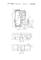
- FIG. 1 is an elevational schematic representation of a balanced draft vapor generator incorporating the present invention
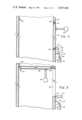
- FIG. 2 is a fragmentary elevational section of the implosion door of the present invention illustrated in its closed position;
- FIG. 3 is a view similar to FIG. 2 showing the implosion door of the present invention in its released position;
- FIG. 4 is an end view taken along line 4--4 of FIG. 1;
- FIG. 5 is a view similar to FIG. 4 illustrating another embodiment of the invention.
- the vapor generator organization 10 illustrated in FIG. 1 includes a vapor drum 12. This drum supplies liquid separated from the vapor-liquid mixture supplied thereto through downcomers 14 to the lower water wall headers 16, 18 and 20 to which are connected the lower ends of water cooled tubes 22 forming walls and roof of the furnace chamber 24. The upper ends of some of the aforesaid water cooled tubes 22 are connected directly to vapor drum 12. Others terminate in the upper wall header 26 which, in turn, communicate with drum 12 through connecting tubes.
- Burners 30 are located in the lower portion of the furnace chamber 24. Fuel and air are discharged through these burners into the furnace chamber 24 where combustion occurs. The combustion gases generated in the furnace chamber are caused to flow upwardly towards the furnace outlet 32 while giving off a substantial portion of the heat contained therein to the tubes 22 for vapor generation purposes. In leaving the furnace chamber 24 the gases enter the horizontal and vertical gas passes 34 and 36 respectively in which vapor heating devices, such as the primary and secondary superheaters, 38 and 40 respectively, are located. Additional heat absorbing surface such as economizer 42 may be arranged in the gas pass 36 through which the gases flow on their way to a stack (not shown).
- the herein described vapor generator organization is of the balanced draft type in which forced draft fan 44 in association with dampers (not shown) controls the flow of combustion air to burners 30 while induced draft fan 46 operates to regulate the extraction flow of combustion gases from the unit for ultimate discharge from the stack.
- the forced draft fan 44 communicates with the burner wind box 48 through a duct 50 which passes incoming air through the air side 52 of an air heater 54.
- the induced draft fan 46 connects with the discharge end of the gas pass 36 by means of duct 56 that extends through the gas side 58 of the air heater 54.
- operation of the induced draft fan is such as to maintain fluid pressure in the furnace chamber 24 at slightly below atmospheric pressure. In this way leakage of combustion gas from the unit is prevented.
- the wall in a vertical run of the duct 56 is provided with one or more through openings 60 by means of which open communication is made between the interior of the combustion gas flow passage and the exterior of the unit.
- Each opening 60 is closed by a closure door 62 which, as shown best in FIGS. 2 and 3, is adapted for pivotal movement into the interior of the duct 56 by means of hinge construction 64.
- the door 62 is preferably sized to extend substantially fully transversely of the duct interior and a stop in the form of angle member 66 is provided on the duct wall opposite that containing the door to locate the door, in its released position, across the duct section.
- a counterweight 65 may be provided on the door to assist its movement to its released position.
- the door is maintained closed during normal operation of the unit by a latching mechanism, indicated generally as 67, with appropriate sealing members 68 being provided to prevent combustion gas leakage across the seam.
- the latching mechanism 67 employed in the illustrated embodiment of the invention comprises a cam member 68 that is pivotally attached to the duct wall adjacent the opening 69. At one end the cam member contains a finger 70 engagable with bracket 72 on the free end of the door 62. At its other end the cam member contains a second finger 74 that is engaged by a pivotally mounted latch 76.
- the latch 76 is actuated by an electrically operated solenoid actuator 78 whose armature 80 connects with the latch.
- the solenoid actuator 78 is arranged for operation upon the occurrence of a predetermined excess negative pressure level within the furnace chamber 24 as determined by an appropriate pressure sensing device 82 (FIG. 1).
- the solenoid actuator 78 is energized to actuate latching mechanism 68 for releasing the door 62.
- the door pivots under the influence of the counterweight 65 and the differential pressure across the door to its released position against the stop 66. In this position the door 62 provides an obstruction in the combustion flow path restricting the flow of gas from the furnace chamber 24. Simultaneously therewith, continued operation of the forced draft fan 44 serves to admit more air to the furnace chamber thereby pressurizing the latter to overcome the excessive negative pressure excursion.
- the fan By means of the exposure of the suction side of the induced draft fan to the exterior of the unit through the opening 60 upon release of the door 62, the fan is prevented from producing a high negative static pressure on the downstream side of the door which would otherwise have a tendency to return the same to its closed position.
- the described embodiment of the invention utilizes a plurality of openings 60 with associated closure doors 62 laterally spaced across the wall of duct 56.
- Each of the respective closure doors 62 is released upon energization of its associated solenoid actuator 78, each of which actuators is set to respond to a different pressure in the furnace chamber 24.
- solenoid actuators 78 each of which actuators is set to respond to a different pressure in the furnace chamber 24.
- the solenoid actuators can be set for simultaneous energization whereby the doors will be released simultaneously or, as shown in FIG. 5, the inventive concept can be implemented by only a single opening 60 having an associated closure door 62.
- the door 62 is dimensioned to substantially fully obstruct, when released, the gas passage defined by the interior of the duct.
Landscapes
- Engineering & Computer Science (AREA)
- Chemical & Material Sciences (AREA)
- Combustion & Propulsion (AREA)
- Mechanical Engineering (AREA)
- General Engineering & Computer Science (AREA)
- Regulation And Control Of Combustion (AREA)
- Air Supply (AREA)
Priority Applications (3)
| Application Number | Priority Date | Filing Date | Title |
|---|---|---|---|
| US05/535,742 US3957001A (en) | 1974-12-23 | 1974-12-23 | Furnace implosion door |
| CA235,832A CA1028571A (en) | 1974-12-23 | 1975-09-18 | Furnace implosion door |
| JP15204275A JPS5189227A (enExample) | 1974-12-23 | 1975-12-22 |
Applications Claiming Priority (1)
| Application Number | Priority Date | Filing Date | Title |
|---|---|---|---|
| US05/535,742 US3957001A (en) | 1974-12-23 | 1974-12-23 | Furnace implosion door |
Publications (1)
| Publication Number | Publication Date |
|---|---|
| US3957001A true US3957001A (en) | 1976-05-18 |
Family
ID=24135574
Family Applications (1)
| Application Number | Title | Priority Date | Filing Date |
|---|---|---|---|
| US05/535,742 Expired - Lifetime US3957001A (en) | 1974-12-23 | 1974-12-23 | Furnace implosion door |
Country Status (3)
| Country | Link |
|---|---|
| US (1) | US3957001A (enExample) |
| JP (1) | JPS5189227A (enExample) |
| CA (1) | CA1028571A (enExample) |
Cited By (3)
| Publication number | Priority date | Publication date | Assignee | Title |
|---|---|---|---|---|
| US4770108A (en) * | 1987-07-28 | 1988-09-13 | Abar Ipsen Industries, Inc. | Two-way vent cap for controlled atmosphere furnace |
| US20060065308A1 (en) * | 2004-09-29 | 2006-03-30 | Rogge Timothy J | Pressure relief door for air duct work |
| US8650801B2 (en) | 2011-03-01 | 2014-02-18 | Bha Altair, Llc | Pressure relief door with counterweight mechanism |
Citations (5)
| Publication number | Priority date | Publication date | Assignee | Title |
|---|---|---|---|---|
| US2160262A (en) * | 1936-07-06 | 1939-05-30 | Baker Perkins Co Inc | Explosion door for furnaces |
| US2989039A (en) * | 1954-08-27 | 1961-06-20 | Babcock & Wilcox Co | Fluid heating unit with gas tempering provisions |
| US3071448A (en) * | 1959-06-15 | 1963-01-01 | Combustion Eng | Chemical recovery unit with improved superheater construction |
| US3297251A (en) * | 1965-01-14 | 1967-01-10 | Conco Engineering Works Inc | Double acting draft control with sleeve |
| US3782411A (en) * | 1972-06-30 | 1974-01-01 | United Mcgill Corp | Duct access section |
Family Cites Families (1)
| Publication number | Priority date | Publication date | Assignee | Title |
|---|---|---|---|---|
| JPS4936442A (enExample) * | 1972-08-07 | 1974-04-04 |
-
1974
- 1974-12-23 US US05/535,742 patent/US3957001A/en not_active Expired - Lifetime
-
1975
- 1975-09-18 CA CA235,832A patent/CA1028571A/en not_active Expired
- 1975-12-22 JP JP15204275A patent/JPS5189227A/ja active Pending
Patent Citations (5)
| Publication number | Priority date | Publication date | Assignee | Title |
|---|---|---|---|---|
| US2160262A (en) * | 1936-07-06 | 1939-05-30 | Baker Perkins Co Inc | Explosion door for furnaces |
| US2989039A (en) * | 1954-08-27 | 1961-06-20 | Babcock & Wilcox Co | Fluid heating unit with gas tempering provisions |
| US3071448A (en) * | 1959-06-15 | 1963-01-01 | Combustion Eng | Chemical recovery unit with improved superheater construction |
| US3297251A (en) * | 1965-01-14 | 1967-01-10 | Conco Engineering Works Inc | Double acting draft control with sleeve |
| US3782411A (en) * | 1972-06-30 | 1974-01-01 | United Mcgill Corp | Duct access section |
Cited By (4)
| Publication number | Priority date | Publication date | Assignee | Title |
|---|---|---|---|---|
| US4770108A (en) * | 1987-07-28 | 1988-09-13 | Abar Ipsen Industries, Inc. | Two-way vent cap for controlled atmosphere furnace |
| US20060065308A1 (en) * | 2004-09-29 | 2006-03-30 | Rogge Timothy J | Pressure relief door for air duct work |
| US7275560B2 (en) * | 2004-09-29 | 2007-10-02 | A.J. Manufacturing, Inc. | Pressure relief door for air duct work |
| US8650801B2 (en) | 2011-03-01 | 2014-02-18 | Bha Altair, Llc | Pressure relief door with counterweight mechanism |
Also Published As
| Publication number | Publication date |
|---|---|
| CA1028571A (en) | 1978-03-28 |
| JPS5189227A (enExample) | 1976-08-04 |
Similar Documents
| Publication | Publication Date | Title |
|---|---|---|
| US3957001A (en) | Furnace implosion door | |
| US3477411A (en) | Heat recovery boiler with bypass | |
| US10712001B2 (en) | Combustion device | |
| US3403962A (en) | Power venter for gas fired appliances | |
| US2259299A (en) | Heating apparatus | |
| CA1118308A (en) | Blow back prevention apparatus for a wood-burning stove | |
| US3921546A (en) | Implosion door operating mechanism | |
| US2576373A (en) | Oil-burning boiler fire box with air and steam feeding means | |
| US2661794A (en) | Oil burner having pneumatic secondary air control | |
| US2088299A (en) | Heating apparatus | |
| GB899850A (en) | Improvements in vapour generating units | |
| US1721735A (en) | Reversing and controlling apparatus for heating furnaces | |
| US1387463A (en) | Superheat-regulator | |
| US3023716A (en) | Pressure fired furnace | |
| US3805764A (en) | Heating system with exterior air inlet for combustion chamber | |
| US1611766A (en) | Apparatus for hot-air heating systems | |
| US3092320A (en) | Combustion control with combustion air and draft diversion air control system | |
| US620380A (en) | toomey | |
| US2231975A (en) | Heating apparatus | |
| US1492135A (en) | Oil-burning apparatus | |
| US2567452A (en) | Superheater for furnaces | |
| JP2640950B2 (ja) | ガスバーナー用燃焼装置 | |
| US2222893A (en) | Solid fuel burning furnace | |
| US1328997A (en) | Superheat-limiting device | |
| US590846A (en) | Steam-boiler furnace |