US395681A - John aitken - Google Patents
John aitken Download PDFInfo
- Publication number
- US395681A US395681A US395681DA US395681A US 395681 A US395681 A US 395681A US 395681D A US395681D A US 395681DA US 395681 A US395681 A US 395681A
- Authority
- US
- United States
- Prior art keywords
- drum
- case
- cord
- disks
- attached
- Prior art date
- Legal status (The legal status is an assumption and is not a legal conclusion. Google has not performed a legal analysis and makes no representation as to the accuracy of the status listed.)
- Expired - Lifetime
Links
- 239000002965 rope Substances 0.000 description 4
- 235000007575 Calluna vulgaris Nutrition 0.000 description 2
- 241001272567 Hominoidea Species 0.000 description 2
- 241000353097 Molva molva Species 0.000 description 2
- 239000002184 metal Substances 0.000 description 2
- 230000001105 regulatory Effects 0.000 description 2
Images
Classifications
-
- A—HUMAN NECESSITIES
- A62—LIFE-SAVING; FIRE-FIGHTING
- A62B—DEVICES, APPARATUS OR METHODS FOR LIFE-SAVING
- A62B1/00—Devices for lowering persons from buildings or the like
- A62B1/06—Devices for lowering persons from buildings or the like by making use of rope-lowering devices
- A62B1/08—Devices for lowering persons from buildings or the like by making use of rope-lowering devices with brake mechanisms for the winches or pulleys
- A62B1/10—Devices for lowering persons from buildings or the like by making use of rope-lowering devices with brake mechanisms for the winches or pulleys mechanically operated
Definitions
- This invention relates to a fire-escape adapted to be carried about from place to place; but the same may be constructed of any desired size.
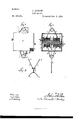
- Figure 1 is a front elevation of the improved fire-escape.
- Fig. 2 is a vertical section in a plane parallel to the front face of the casing; and
- Fig. illust *ates a device for suspending the apparatus.
- My improved fire-escape is constructed as follows: I make use of a case, A, preferably of metal, having within it a shaft, B, with journals 0, arranged to revolve in bearings in the sides of the case.
- 'D is a drum attached to the shaft, the surface of said drum being divided by disks 1 2 3 4 5 6, attached to the drum or formed integral therewith
- the shaft 13, drum D, and disks may all be cast or otherwise formed of one piece.
- E is a cord, preferably of wire, one end of which is attached to the drum between the disks 1 and 2, and the other end passed out through an opening in the upper part of the case, thence through another opening in the upper part of the case back to the drum between the disks 5 and 6, and there secured to the drum.
- F is another similar cord with one end attached to the drum between the disks 2 and 3, and the other end passed out through an opening in the lower part of the case, and thence through another opening in the lower part of the case back to the drum between the disks 4.- and 5, and there secured to the drum.
- cords E and F instead of being continuous, may be separate cords and attached to a bar or ring outside the case, as hereinafterdescribed.
- G is a cord or rope with one end attached to the center of the drum between the disks 3 and 4, and the other end passed out through an opening in the center of the lower part of the case.
- the openings in the case though which the cords E, F, and G pass are elongated laterally, to prevent wear upon the cords by contact with the edges when in operation, and, if desired, rollers may be employed at the openings for the wires to pass over.
- This fire-escape is to be suspended from a window or any part of a building by connect ing the cord E with any suitable suspending device, such as the chains 7, hooks 8, and snap-hook 9. (Shown in Fig. 3.)
- a suitable brake mechanism may be employed. I have shown brake-levers J J, provided with friction brake-shoes L, said levers being pivoted to the arms K, attached to the case.
- M M are screws by which the pressure of the brake-shoes upon the ends of the drum can be regulated.
- a person using this fire-escape may simply grasp the ring I with his hands; but said ring I may be dispensed with and any suitable sling be attached to the cord F.
- ⁇ Vhen desirin to use this fire-escape, a per son throws the ball of cord G to the ground, and, grasping the ring I or other attachment, his weight causes the shaft B to revolve, thus gradually uncoi ling the wire cords E and F from the drum, and at the same time the cord G will wind upon the drum.
- cords E and 1* attached to the drum andpassed outside the case and there attached to a ring or bar, and the cord G, one end of which is fastened to the drum after the cords E and F have been coiled upon said drum, and a suspending device, substantially as specified,
Description
(No Model) J. AITKEN.
FIRE ESCAPE.
N. PU'EFIS Fhcio-Lill'ographer. Washingwn. D. c.
UNITED STATES PATENT rricn.
JOHN AITKEN, OF NEIV YORK, N. Y.
Fl RE ESCAPE.
SPECIFICATION forming part of Letters Patent No. 395,681, dated January 8, 1889. Application filed April 23, 1888. Serial No. 271,603. (No model.)
To aZZ whom it may concern.-
Be it known that I, JOHN AITKEN, of the city, county, and State of New York, have invented an Improvement in FireEs apes, of which the following is a specification.
This invention relates to a fire-escape adapted to be carried about from place to place; but the same may be constructed of any desired size.
In the drawings, Figure 1 is a front elevation of the improved fire-escape. Fig. 2 is a vertical section in a plane parallel to the front face of the casing; and Fig. illust *ates a device for suspending the apparatus.
My improved fire-escape is constructed as follows: I make use of a case, A, preferably of metal, having within it a shaft, B, with journals 0, arranged to revolve in bearings in the sides of the case.
'D is a drum attached to the shaft, the surface of said drum being divided by disks 1 2 3 4 5 6, attached to the drum or formed integral therewith The shaft 13, drum D, and disks may all be cast or otherwise formed of one piece.
E is a cord, preferably of wire, one end of which is attached to the drum between the disks 1 and 2, and the other end passed out through an opening in the upper part of the case, thence through another opening in the upper part of the case back to the drum between the disks 5 and 6, and there secured to the drum. F is another similar cord with one end attached to the drum between the disks 2 and 3, and the other end passed out through an opening in the lower part of the case, and thence through another opening in the lower part of the case back to the drum between the disks 4.- and 5, and there secured to the drum.
It will be obvious that either orboth of the cords E and F, instead of being continuous, may be separate cords and attached to a bar or ring outside the case, as hereinafterdescribed.
G is a cord or rope with one end attached to the center of the drum between the disks 3 and 4, and the other end passed out through an opening in the center of the lower part of the case.
The openings in the case though which the cords E, F, and G pass are elongated laterally, to prevent wear upon the cords by contact with the edges when in operation, and, if desired, rollers may be employed at the openings for the wires to pass over.
In constructing this lire-escape, after the wire cords E and F have been attached to the drum in the manner aforesaid, they are then coiled upon the drum D by revolving the shaft 15. After this has been done the cord or rope G is attached to the drum in the manner before described, and, being of the desired length, that portion projecting outside the case is wound in a ball or upon a stick, as maybe preferreijl, and is then placed within a suitable receptacle, 0, provided for it in the case, so as to be easy of access when it is desired to use the fire-escape.
\Vhen the cords E and F are not continuous, I provide the rings H and I, to which the ends of the cords E and F which are outside the case are attached; or a bar or bars may be employed instead of the rings, as shown by dotted lines in Fig. 1.
This fire-escape is to be suspended from a window or any part of a building by connect ing the cord E with any suitable suspending device, such as the chains 7, hooks 8, and snap-hook 9. (Shown in Fig. 3.)
If desired, a suitable brake mechanism may be employed. I have shown brake-levers J J, provided with friction brake-shoes L, said levers being pivoted to the arms K, attached to the case.
M M are screws by which the pressure of the brake-shoes upon the ends of the drum can be regulated.
A person using this fire-escape may simply grasp the ring I with his hands; but said ring I may be dispensed with and any suitable sling be attached to the cord F.
\Vhen desirin to use this lire-escape, a per son throws the ball of cord G to the ground, and, grasping the ring I or other attachment, his weight causes the shaft B to revolve, thus gradually uncoi ling the wire cords E and F from the drum, and at the same time the cord G will wind upon the drum.
It will be apparent that the operator can control the velocity of his descent by means of the cord G, and that when he reaches the ground the wire cords E and F can be re-coi1ed upon the drum by pulling upon the cord G, which will unwind at the same time, and that the device will then be again in readiness for use. It will also be apparent that by means of the cord G a person below may guide the descent or prevent the device from coinin g in contact with any part of a building.
I claim as my invention 1. In a fire-escape, the combination of the case A, shaft 13, drum D, mounted on the shaft, disks 1 2 3 4 5 (5, attached to the drum, cords E, F, and G, and a suspending device, to which the cord E is connected, substantially as and operating in the manner specified.
2. The combination of the case A, revolving drum D, disks 1 2 3 a 5 6, attached to the drum, the wire cord E, having one end secured to the drum between the disks 1. and 2, and the other end secured to the drum between the disks 5 and 6, the wire cord F, having one end fastened to the drum between the disks 2 and 3, and the other end secured to the drum between the disks 4 and 5, and the cord G, one end of which is fastened to the center of the drum between the disks and at, after the cords E and F have been coiled upon the drum, and the other end passed out through. an opening in the lower part of the case, and a suspending device, to which the cord E is connected, substantially as described.
case A, shaft B, drum D, disks 1 2 3 4 5 6, the
cords E and 1*, attached to the drum andpassed outside the case and there attached to a ring or bar, and the cord G, one end of which is fastened to the drum after the cords E and F have been coiled upon said drum, and a suspending device, substantially as specified,
5. In a fire-escape, the combination of the case A, shaft B, drum D, disks 1 2 3 4 5 6, and cords E, F, and G, attached to the drum, substantially as specified.
JOHN AITKE'N.
\Vitnesses:
THOS. H. HARTWELL, GEO. T. PINCKNEY.
Publications (1)
| Publication Number | Publication Date |
|---|---|
| US395681A true US395681A (en) | 1889-01-08 |
Family
ID=2464651
Family Applications (1)
| Application Number | Title | Priority Date | Filing Date |
|---|---|---|---|
| US395681D Expired - Lifetime US395681A (en) | John aitken |
Country Status (1)
| Country | Link |
|---|---|
| US (1) | US395681A (en) |
Cited By (4)
| Publication number | Priority date | Publication date | Assignee | Title |
|---|---|---|---|---|
| US2490378A (en) * | 1944-06-29 | 1949-12-06 | Intertype Corp | Single cable advancing mechanism and method |
| US2617242A (en) * | 1947-11-20 | 1952-11-11 | Case Co J I | Hydraulic ram for raising sickle bars |
| US3122221A (en) * | 1959-11-11 | 1964-02-25 | Porsche Kg | Disk brake for vehicles including manually operated expanding shoe brake |
| US3202379A (en) * | 1963-04-01 | 1965-08-24 | Pacific Scientific Co | Safety harness device |
-
0
- US US395681D patent/US395681A/en not_active Expired - Lifetime
Cited By (4)
| Publication number | Priority date | Publication date | Assignee | Title |
|---|---|---|---|---|
| US2490378A (en) * | 1944-06-29 | 1949-12-06 | Intertype Corp | Single cable advancing mechanism and method |
| US2617242A (en) * | 1947-11-20 | 1952-11-11 | Case Co J I | Hydraulic ram for raising sickle bars |
| US3122221A (en) * | 1959-11-11 | 1964-02-25 | Porsche Kg | Disk brake for vehicles including manually operated expanding shoe brake |
| US3202379A (en) * | 1963-04-01 | 1965-08-24 | Pacific Scientific Co | Safety harness device |
Similar Documents
| Publication | Publication Date | Title |
|---|---|---|
| US395681A (en) | John aitken | |
| US656507A (en) | Fire-escape. | |
| US374596A (en) | District of co | |
| US437091A (en) | Fire-escape | |
| US482813A (en) | Michael schwarz | |
| US939375A (en) | Fire-escape. | |
| US295047A (en) | Fire-escape | |
| US778743A (en) | Fire-escape. | |
| US646635A (en) | Fire-escape. | |
| US728145A (en) | Fire-escape. | |
| US481252A (en) | Fire-escape | |
| US1167239A (en) | Portable fire-escape. | |
| US294908A (en) | Fire-escape | |
| US199199A (en) | Improvement in fire-escapes | |
| US652621A (en) | Fire-escape. | |
| US301657A (en) | Fire-escape | |
| US715330A (en) | Fire-escape. | |
| US234828A (en) | Fire-escape | |
| US1191504A (en) | Fire-escape. | |
| US772056A (en) | Fire-escape. | |
| US1147365A (en) | Fire-escape. | |
| US588894A (en) | Portable automatic fire-escape | |
| US493490A (en) | Fiee escape | |
| US764339A (en) | Fire-escape. | |
| US829211A (en) | Fire-escape and the like. |