US395675A - weeks - Google Patents
weeks Download PDFInfo
- Publication number
- US395675A US395675A US395675DA US395675A US 395675 A US395675 A US 395675A US 395675D A US395675D A US 395675DA US 395675 A US395675 A US 395675A
- Authority
- US
- United States
- Prior art keywords
- plunger
- pump
- punch
- lever
- packing
- Prior art date
- Legal status (The legal status is an assumption and is not a legal conclusion. Google has not performed a legal analysis and makes no representation as to the accuracy of the status listed.)
- Expired - Lifetime
Links
- 239000007788 liquid Substances 0.000 description 18
- 238000012856 packing Methods 0.000 description 16
- 239000002184 metal Substances 0.000 description 7
- 230000000994 depressogenic effect Effects 0.000 description 5
- 238000010276 construction Methods 0.000 description 4
- 230000009286 beneficial effect Effects 0.000 description 1
- 210000004907 gland Anatomy 0.000 description 1
- 238000003780 insertion Methods 0.000 description 1
- 230000037431 insertion Effects 0.000 description 1
- 239000000463 material Substances 0.000 description 1
- 238000004080 punching Methods 0.000 description 1
- 238000005406 washing Methods 0.000 description 1
Images


Classifications
-
- B—PERFORMING OPERATIONS; TRANSPORTING
- B66—HOISTING; LIFTING; HAULING
- B66F—HOISTING, LIFTING, HAULING OR PUSHING, NOT OTHERWISE PROVIDED FOR, e.g. DEVICES WHICH APPLY A LIFTING OR PUSHING FORCE DIRECTLY TO THE SURFACE OF A LOAD
- B66F3/00—Devices, e.g. jacks, adapted for uninterrupted lifting of loads
- B66F3/24—Devices, e.g. jacks, adapted for uninterrupted lifting of loads fluid-pressure operated
- B66F3/25—Constructional features
- B66F3/42—Constructional features with self-contained pumps, e.g. actuated by hand
Definitions
- HYDRAULIC PUNCH &c. No. 395,675. Patented Jan. 1, 1889.
- HYDRAULIC PUNCH 81,0.
- My invention relates to improvements in hydraulic punches, a part of them being also applicable to other like hydraulic implements; and it consists, among other things, in, first, improvements in the construction and operation of the pump of the punch; second, in adapting and arranging the reservoir of the punch relative to the pump in such manner that the punch may be operated irrespective of the position of the punch, or, in other words, the direction of the punching, whether up, down, horizontally, or at any intermediate angle; and, third, to improvements in the socket and pumpinglever.
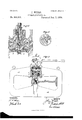
- Figure 1 illustrates a view, partly in vertical section, of thepunch.
- Fig. 2 illustrates a horizontal section taken through the center of the head on the line a a of Fig. 1.
- Fig. 3 illustrates a plan of the head, showing the socket, pumpingdever, and lowering-lever.
- Fig. 4 illustrates an end view of the pumping-lever.
- Fig. 5 illustates a longitudinal sectional view of an alternative construction of the backflowpassages in the plunger and in the pump.
- Fig. 6 illustrates a horizontal section of a pump in which the backflow-passages through the pum p-chamber are made in the form of grooves in the wall thereof.
- Fi 7 illustrates, partly in section, a beammnch, showing the spring for retracting the punch and ram.
- A is the frame of the punch. It is preferably made of wrougl1tsteel, but maybe made of any suitable material.
- B is the head or reservoir of the punch, which is preferably threaded into the frame A by screw-threads a.
- C is a cap or cover threaded onto the head, as shown. It is provided with a screw-plug,
- E is the pump, which is threaded into the base of the head by screwthreads b.
- the pump projects into the reservoir, as shown, and the capacity and dimensions of the head are such that the suction-ports of the pump will always be covered by the liquid in the head irrespective of the position.
- the punch may always be operatedthat is to say, the upper end of the pump is carried so far toward the center of the reservoir, and the liquid capacity of the reservoir is such that the amount of liquid required to fullyproject the ram will not re prise the amount of liquid in the reservoir so but that the suction-ports in the piston will always be covered by the liquid, irrespective of the degree of projection of the ram, and also irrespective of the position of the punch as a whole.
- F is the socket
- G is the socket-pin
- H is a packing for the socketpin.
- I is a knuckle or crank-pin attached to the side of the socket-pin, as shown.
- J is a plunger which works in the pump.
- the diameter of that part of the plunger which passes through the packing thereof and enters the bore of the pump is considerably smaller than the bore of the pump, so that there is free water-passage all around the plunger for the purposes of a backflow of liquid, as hereinafter explained.
- the plunger is attached on its upper end to a plungerhead, K, by means of a pin, 0.
- the plungerhead is recessed and receives the knuckle I within the recess without much play therein.
- the plungenhead is made circular on its sides, which engage with and are guided by correspondii'igly-shaped surfaces of the guide-web L, placed within the head B. It is not, however, essential, that these surfaces should be circular, any 01 her suitable conformation acting as guides; or other suitable guiding devices may be employed.
- the web or guide L is rigidly attached to the walls of the head.
- the plunger J is perforated by a longitudinal passage, (1, and by transverse passages c 6. These transverse passages are so located that when the plunger is so far depressed as to press open the egress-valve, as hereinafter described, then the lower passages e are below the packing of the plunger, marked f; but during the ordinary pun'lping' operation neither of the transverse passages 6 come below the packing.
- the packing maybe of any preferred kind, either a cup-packing, a U-shapcd packing, a hard-ring packing, as shown, or any other desired packing.
- g is a threaded packing-ring or gland for fastening the packing f in place, as usual.
- h is a bonnet attached to the lower end of the plunger, provided with perforations 1' 'i for the free passage of the liquid through them.
- j is the ingress-valve for the pump. It opens downwardly, having its seat at the lower end of the longitudinal passage (Z in the plunger. dropping down into the chamber of the pump.
- This passage 71 is is a downwardly-exteuding hole or passage proceeding from the lower end of the chamber of the pump through the base thereof into the force-chamber of the punch. (Shown at Z.)
- This passage 71 is provided with a stemmed valve, m, which has its seat at the at is a perforated bonnet,substantially the same as the bonnet 70. It is attached to the lower end of the pump.
- 0 is a spring placed within the bonnet n
- p is a packing held in place by a packingring, q, which is held by threads q, out on the lower end of the pump, as shown, or in any other desired manner.
- This packing seals both of the joints a and b.
- M is the ram of the punch. It slides longitudinally through the frame A, which it fits somewhat snugly. It is provided with the packing N, which is held in place by the packing-ring O, which may be confined by screws P, as shown, or in any other suitable manner.
- the ram is recessed at Q, to allow space for the bonnet at when the ram is in its most retracted position.
- R is the punching-tool, which is attached to the lower end of the ram by a pin, S, or in any other suitable manner.
- T is the die, and U the piece of metal to be punched.
- the stems of the valves j and m are made triangular, as usual, to allow liquid passage past them.
- F is the socket, before referred to
- V is the pumping-lever.
- the lever is so made that it can pass through the socket F and project beyond the same, say, half or three-quarters of an inch, as shown at V. This is so that if the punch be inverted so as to punch up instead of down, the pumping-lever may be inserted from the other side of the socket, and the projecting end V will then act as a stop against the end 0 of the lug
- the bonnet hprecons the valve j from W in the same manner that the part marked a; of the lever acts when the punch is used right-side up. In this way the downstroke of the lever is made the pumping-stroke, irrespective of the position of the punch.
- the lever V has shoulders on its sides, as shown in Fig. 4, to prevent it from passing too far through the socket.
- the lug ⁇ V is a double stop-lug-that is to say, it has one shoulder, 0'', against which the lever strikes when. at the end of the p um pin g-stroke, and another shoulder, 0', against which the end of the socket strikes when the plunger of the pump has been carried down sufficiently far to force the egress-valve off its seat to secure the backflow of liquid.
- X is a lever or rod which, when the pumpin g-lever V has been removed from the socket,
- a second hole, :11" is preferably made in the socket for the insertion of the rod X when the machine is upside down. This is not essential, but is convenient.
- Fig. 5 I illustrate an. alternative construction of the backflow-passages in the plunger, and also in the pump-that is to say, instead of the transverse passages e e connecting with the longitudinal passage d, there are what may be called ingress-passages e 6, connecting with the longitudinal passage (1; but they are not used for the backflow, but simply for the illflow of liquid to the pump-chamber. Other passages in the form of grooves c" e are provided for the backflow.
- these grooves are made, as shown, in the periphery of the plunger, and are so located and of such length that when the plunger is depressed sufliciently to open the egress-valve these grooves will connect with the chamber of the pump at their lower end and with the reservoir at their upper end.
- the plunger may substantially fit the bore of the pump-chamber, but with grooves f, Figs. 5 and 6, made in the walls thereof, which c011- nect with the egrcss-passage 7tand with the backliow-passagcs in the plunger wheirit is depressed to open the egress-valve; and, instead of these grooves opening into the chamber of the pump throughout their length, they may be made as concealed holes bored in the metal within the wall of the pump-chamber, as seen at f", Fig. 5, connecting by transverse passagesf with the egress-passage 7.5 below and the backtlow passages in the plunger above.
- Fig. 7 I illustrate the devices for retracting the ram and punch.
- the frame of the punch is carried inwardly, presenting a eircumferential or annular shoulder, A.
- the ram M is reduced in diameter in a part of its length to conform to the size of the hole in the frame within this annularshoulder.
- the upper part of the ram is of the diameter of the force-chamber Z, thus producing the annularshoulders B on the rain.
- a heavy spring, 0, is placed between the shoulder A and B, which spring is compressed by the outward movement of the ram, as shown in Fig. 7.
- This spring may be a spiral spring, as shown, surrounding the ram, or a convoluted plate-spring.
- the operation is as follows: The work to be punched is placed, or the punch is moved, so as to bring the metal to be punched over the die T and in proper line with the punch.
- the lever V is then operated as usual, and the liquid from the reservoir or head B of the punch at each upstroke of the plunger pass s through the transverse and longitudinal passages in the plunger, through the ingress valve at its end, through, the perforation in the bonnet 71., and into the force-chamber of the pump.
- retraeting-spring C may be employed in punches of the kind shown in Fig. 1, as well as in the beam-punches shown in Fig. 7, by a similar construction of the coacting parts.
- I claim 1 The combination of a reservoir and a pump, the suction whereof is located at ornear the center of the reservoir, and the plunger or piston whereof is provided with an ingressvalve which opens on the upstroke but closes on the downstroke of the piston or plunger, a :forcechamli)er, the liquid capacity of which is such relative to that of the reservoir that when the ram is projected to its utmost limit there will still be suliicient liquid in the reservoir to cover the suction of the pump irrespective of the position of the apparatus and mechanism to operate the pump, substantially as set forth.
Landscapes
- Life Sciences & Earth Sciences (AREA)
- Engineering & Computer Science (AREA)
- Geology (AREA)
- Mechanical Engineering (AREA)
- Structural Engineering (AREA)
- Details Of Reciprocating Pumps (AREA)
Description
(No Model.) 3 Sheets-Sheet 1.
J. WEEKS.
HYDRAULIC PUNCH, &c. No. 395,675. Patented Jan. 1, 1889.
WITNESSES;
ATTORNEY,
N. PETERS, PhnluLilhoghpMr. Washi nnnnnnn C.
(No Model.) s Sheets Sheet 2. J. WEEKS.
HYDRAULIG PUNCH, &c. No. 395,675. Patented Jan. 1, 1889.
W BY? 7,
ATTORNEY.
3 Sheets-Sheet 3.
(No Model.)
J. WEEKS.
9 O0 8 11 1 n a u d e t .n 06 &t 1a HP 0 N U P nu T. L U A R D Y H 5 7 6 5 9 3 O N WITNESSES:
l VEJOR ATTORNEY rrn grates PATENT trier.
JOHN YVEEKS, OF NEW YORK, N. Y., ASSIGNOR TO RICHARD DUDGEON, OF SAME PLACE.
HYDRAULIC PUNCH, 81,0.
SPECIFICATION forming part of Letters Patent No. 395,675, dated January 1, 1889. Application filed January 28, 1887. Serial No. 225,758 (No model.)
To aZZ whom it may concern.
Be it known that I, JOHN lVEEKs, a citizen of the United States, and a resident of New York city, in the county of New York and State of New York, have invented certain new and useful Improvements in Hydraulic Punches and Like Apparatus, of which the following is a specification.
' My invention relates to improvements in hydraulic punches, a part of them being also applicable to other like hydraulic implements; and it consists, among other things, in, first, improvements in the construction and operation of the pump of the punch; second, in adapting and arranging the reservoir of the punch relative to the pump in such manner that the punch may be operated irrespective of the position of the punch, or, in other words, the direction of the punching, whether up, down, horizontally, or at any intermediate angle; and, third, to improvements in the socket and pumpinglever.
In the drawings the same reference-letters indicate the same parts in all the figures.
Figure 1 illustrates a view, partly in vertical section, of thepunch. Fig. 2 illustrates a horizontal section taken through the center of the head on the line a a of Fig. 1. Fig. 3 illustrates a plan of the head, showing the socket, pumpingdever, and lowering-lever. Fig. 4: illustrates an end view of the pumping-lever. Fig. 5 illust ates a longitudinal sectional view of an alternative construction of the backflowpassages in the plunger and in the pump. Fig. 6 illustrates a horizontal section of a pump in which the backflow-passages through the pum p-chamber are made in the form of grooves in the wall thereof. Fi 7 illustrates, partly in section, a beammnch, showing the spring for retracting the punch and ram.
A is the frame of the punch. It is preferably made of wrougl1tsteel, but maybe made of any suitable material.
B is the head or reservoir of the punch, which is preferably threaded into the frame A by screw-threads a.
C is a cap or cover threaded onto the head, as shown. It is provided with a screw-plug,
D, which can be easily removed for filling the head with liquid or for washing the reservoir out and substituting a fresh charge of liquid.
E is the pump, which is threaded into the base of the head by screwthreads b. The pump projects into the reservoir, as shown, and the capacity and dimensions of the head are such that the suction-ports of the pump will always be covered by the liquid in the head irrespective of the position. of the punch, whether upside down or at any intermediate angle, so that the punch may always be operatedthat is to say, the upper end of the pump is carried so far toward the center of the reservoir, and the liquid capacity of the reservoir is such that the amount of liquid required to fullyproject the ram will not re duce the amount of liquid in the reservoir so but that the suction-ports in the piston will always be covered by the liquid, irrespective of the degree of projection of the ram, and also irrespective of the position of the punch as a whole.
F is the socket, and G is the socket-pin.
H is a packing for the socketpin.
I is a knuckle or crank-pin attached to the side of the socket-pin, as shown.
J is a plunger which works in the pump. The diameter of that part of the plunger which passes through the packing thereof and enters the bore of the pump is considerably smaller than the bore of the pump, so that there is free water-passage all around the plunger for the purposes of a backflow of liquid, as hereinafter explained. The plunger is attached on its upper end to a plungerhead, K, by means of a pin, 0. The plungerhead is recessed and receives the knuckle I within the recess without much play therein.
The plungenhead is made circular on its sides, which engage with and are guided by correspondii'igly-shaped surfaces of the guide-web L, placed within the head B. It is not, however, essential, that these surfaces should be circular, any 01 her suitable conformation acting as guides; or other suitable guiding devices may be employed.
The web or guide L is rigidly attached to the walls of the head. The plunger J is perforated by a longitudinal passage, (1, and by transverse passages c 6. These transverse passages are so located that when the plunger is so far depressed as to press open the egress-valve, as hereinafter described, then the lower passages e are below the packing of the plunger, marked f; but during the ordinary pun'lping' operation neither of the transverse passages 6 come below the packing.
The packing maybe of any preferred kind, either a cup-packing, a U-shapcd packing, a hard-ring packing, as shown, or any other desired packing.
g is a threaded packing-ring or gland for fastening the packing f in place, as usual.
h is a bonnet attached to the lower end of the plunger, provided with perforations 1' 'i for the free passage of the liquid through them.
j is the ingress-valve for the pump. It opens downwardly, having its seat at the lower end of the longitudinal passage (Z in the plunger. dropping down into the chamber of the pump.
is is a downwardly-exteuding hole or passage proceeding from the lower end of the chamber of the pump through the base thereof into the force-chamber of the punch. (Shown at Z.) This passage 71; is provided with a stemmed valve, m, which has its seat at the at is a perforated bonnet,substantially the same as the bonnet 70. It is attached to the lower end of the pump.
0 is a spring placed within the bonnet n,
which normally presses the egress-valve m up against its seat.
p is a packing held in place by a packingring, q, which is held by threads q, out on the lower end of the pump, as shown, or in any other desired manner. This packing seals both of the joints a and b.
M is the ram of the punch. It slides longitudinally through the frame A, which it fits somewhat snugly. It is provided with the packing N, which is held in place by the packing-ring O, which may be confined by screws P, as shown, or in any other suitable manner. The ram is recessed at Q, to allow space for the bonnet at when the ram is in its most retracted position.
R is the punching-tool, which is attached to the lower end of the ram by a pin, S, or in any other suitable manner.
T is the die, and U the piece of metal to be punched. The stems of the valves j and m are made triangular, as usual, to allow liquid passage past them.
Referring to Fig. 3, F is the socket, before referred to, and V is the pumping-lever. The lever is so made that it can pass through the socket F and project beyond the same, say, half or three-quarters of an inch, as shown at V. This is so that if the punch be inverted so as to punch up instead of down, the pumping-lever may be inserted from the other side of the socket, and the projecting end V will then act as a stop against the end 0 of the lug The bonnet hpreveuts the valve j from W in the same manner that the part marked a; of the lever acts when the punch is used right-side up. In this way the downstroke of the lever is made the pumping-stroke, irrespective of the position of the punch. The lever V has shoulders on its sides, as shown in Fig. 4, to prevent it from passing too far through the socket. The lug \V is a double stop-lug-that is to say, it has one shoulder, 0'', against which the lever strikes when. at the end of the p um pin g-stroke, and another shoulder, 0', against which the end of the socket strikes when the plunger of the pump has been carried down sufficiently far to force the egress-valve off its seat to secure the backflow of liquid. By the use of this second stop, 7", all danger of crushing the bonnet 7L by carelessness in use is avoided.
X is a lever or rod which, when the pumpin g-lever V has been removed from the socket,
is introduced into a hole, 05', in the socket,
and by its use the socket is depressed still farther until it reaches the shoulder 0", and the egress-valve m is thus opened. A second hole, :11", is preferably made in the socket for the insertion of the rod X when the machine is upside down. This is not essential, but is convenient. The employment of the double stop-lug above described, instead of a single step and a lug or projection on one side of the pumping-lever V, is a marked improvement in the punches herein especially described, and also in hydraulic jacks and other like devices, because with my straight pumping-lever and double stop it is impossible to carry the openings of the passages e eduring the pumpingstrokes past the packing, whereas, if the old style of lever with the lug on one side was thoughtlessly used with the lug reversed, so that it did not engage with the stop, then at each pumping-stroke the plunger might be so far depressed as to cause the openings of the passages e e to sweep across the packing of the plunger, and thus rapidly injure if not destroy it, and itmight even be carried so far down as to trip the egress-valve at each stroke.
In Fig. 5 I illustrate an. alternative construction of the backflow-passages in the plunger, and also in the pump-that is to say, instead of the transverse passages e e connecting with the longitudinal passage d, there are what may be called ingress-passages e 6, connecting with the longitudinal passage (1; but they are not used for the backflow, but simply for the illflow of liquid to the pump-chamber. Other passages in the form of grooves c" e are provided for the backflow. They are made, as shown, in the periphery of the plunger, and are so located and of such length that when the plunger is depressed sufliciently to open the egress-valve these grooves will connect with the chamber of the pump at their lower end and with the reservoir at their upper end. There may be as many of these grooves or passages as desired, and they may be made within the surface of the plunger, being drilled therein, and connecting at each end with the surface of the plunger, if desired. Moreover, instead of making the plunger of less diameter than the bore of the chamber of the pump, so that the baekfiow of the liquid shall be made through the annular space around it, the plunger may substantially fit the bore of the pump-chamber, but with grooves f, Figs. 5 and 6, made in the walls thereof, which c011- nect with the egrcss-passage 7tand with the backliow-passagcs in the plunger wheirit is depressed to open the egress-valve; and, instead of these grooves opening into the chamber of the pump throughout their length, they may be made as concealed holes bored in the metal within the wall of the pump-chamber, as seen at f", Fig. 5, connecting by transverse passagesf with the egress-passage 7.5 below and the backtlow passages in the plunger above.
In Fig. 7 I illustrate the devices for retracting the ram and punch. The frame of the punch is carried inwardly, presenting a eircumferential or annular shoulder, A. The ram M is reduced in diameter in a part of its length to conform to the size of the hole in the frame within this annularshoulder. The upper part of the ram, however, is of the diameter of the force-chamber Z, thus producing the annularshoulders B on the rain. A heavy spring, 0, is placed between the shoulder A and B, which spring is compressed by the outward movement of the ram, as shown in Fig. 7. This spring may be a spiral spring, as shown, surrounding the ram, or a convoluted plate-spring.
I do not limit myself to the employment of the retracting-sprin in connection with hydraulic punches, since they may be employed with beneficial results in screw and lever punches as well.
The operation is as follows: The work to be punched is placed, or the punch is moved, so as to bring the metal to be punched over the die T and in proper line with the punch. The lever V is then operated as usual, and the liquid from the reservoir or head B of the punch at each upstroke of the plunger pass s through the transverse and longitudinal passages in the plunger, through the ingress valve at its end, through, the perforation in the bonnet 71., and into the force-chamber of the pump. At each downstroke of the plunger the liquid in the force-chamber of the pump is displaced by the plunger, and is forced through the egress-valve m and through the perforations in the bonnet n into the forcechamber Z of the punch, compelling the ram M to move slightly outward. This operation is repeated until the punching-tool R has been forced through or partly through the metal and thepunching act is performed.
The lever V is then withdrawn from. the
socket F, and the red X is inserted in the hole iii, by which the socket F is moveddownwardly still farther until it strikes the shoulder r of the stop \V. The adjustment c" e in the periphery of the plunger, as the case may bc-depending on which form of backflow-passages is employed in the plungerare below the packing f. Thus free wa ter way is established from the force-chamber Z through the bonnet n and the valve m, and through the chamber of the pump between the sides of the plunger and the bore of the pump, or through the backtlow-passages f or f made in the walls of the pump-chamber, as the case may be, thence through the passages in the plunger, and out at their upper ends into the reservoir again. As soon as the egress-valve is opened, the spring 0 or its equivalent presses the ram back again into the frame of the punch, withdrawing the punching-tool from the metal which has been punched.
It will sometimes be necessary to jar the metal or the punch by a slight stroke of a hammer or equivalent implement to start the ram and punch back. If the spring 0' be not employed, then the ram and punch may be retracted by means of a forked lever or other suitable instrument applied between the shoulders of the punching-tool R and the surface of the metal, or at any other suitable place, which, being pried upon, forces the ram to move back again. within the frame as the liquid moves out from the chamber 1 I do not limit myself to the details of construetion shown, because they may be departed from somewhat and still the spirit of my invention be employed.
It obvious that the retraeting-spring C may be employed in punches of the kind shown in Fig. 1, as well as in the beam-punches shown in Fig. 7, by a similar construction of the coacting parts.
Having described my invention, I claim 1. The combination of a reservoir and a pump, the suction whereof is located at ornear the center of the reservoir, and the plunger or piston whereof is provided with an ingressvalve which opens on the upstroke but closes on the downstroke of the piston or plunger, a :forcechamli)er, the liquid capacity of which is such relative to that of the reservoir that when the ram is projected to its utmost limit there will still be suliicient liquid in the reservoir to cover the suction of the pump irrespective of the position of the apparatus and mechanism to operate the pump, substantially as set forth.
2. The combination of a recessed socket, double stops cast on the exterior of the reservoir, one below the other, against the upper one of which the pumping-lever strikes 011 the downstroke of the plunger, and against the otherthe socket strikes on the downstroke of the plunger upon the removal of the pump- York and State of New York, this 20th day of ing-lever, and a pumping-lever, both sides January, A7 I). 1887.
whereof, either of which may engage with the i T q stop, are substantially equidistant from the JOHB medial line of the lever, substantially as set *itnesses:
forth. JOHN H. IvEs,
Signed at New York, in the county of New GEORGE A. VOSS.
Publications (1)
| Publication Number | Publication Date |
|---|---|
| US395675A true US395675A (en) | 1889-01-01 |
Family
ID=2464645
Family Applications (1)
| Application Number | Title | Priority Date | Filing Date |
|---|---|---|---|
| US395675D Expired - Lifetime US395675A (en) | weeks |
Country Status (1)
| Country | Link |
|---|---|
| US (1) | US395675A (en) |
Cited By (1)
| Publication number | Priority date | Publication date | Assignee | Title |
|---|---|---|---|---|
| US2563912A (en) * | 1946-01-30 | 1951-08-14 | Julius A Belinkin | Jointed hydraulic jack lever |
-
0
- US US395675D patent/US395675A/en not_active Expired - Lifetime
Cited By (1)
| Publication number | Priority date | Publication date | Assignee | Title |
|---|---|---|---|---|
| US2563912A (en) * | 1946-01-30 | 1951-08-14 | Julius A Belinkin | Jointed hydraulic jack lever |
Similar Documents
| Publication | Publication Date | Title |
|---|---|---|
| DE102018117236A1 (en) | driving tool | |
| US395675A (en) | weeks | |
| US532265A (en) | Portable hydraulic punch | |
| US233419A (en) | jones | |
| US545777A (en) | Elijah beans cornell | |
| US1315019A (en) | Whistle | |
| DE1550315A1 (en) | Valve arrangement for riveting tools | |
| US1226272A (en) | Pile-hammer. | |
| US930781A (en) | Air-pump. | |
| US818001A (en) | Pump. | |
| US402668A (en) | Charles l | |
| US437933A (en) | Ernest w | |
| US845033A (en) | Stuffing-box. | |
| US328730A (en) | thoens | |
| DE138923C (en) | ||
| US1082793A (en) | Press for enlarging holes. | |
| US182710A (en) | Improvement in pumps | |
| US904107A (en) | Lubricator. | |
| US17661A (en) | Machine foe riveting boilebs | |
| US339042A (en) | brooks | |
| US1070429A (en) | Pump. | |
| DE1035170B (en) | Starting aid for refrigeration compressors | |
| US50898A (en) | Improvement in adjusting the packing of pistons in deep wells | |
| US989435A (en) | Oil-can. | |
| US1725496A (en) | Oil-well pump |