US394251A - Piano-action - Google Patents
Piano-action Download PDFInfo
- Publication number
- US394251A US394251A US394251DA US394251A US 394251 A US394251 A US 394251A US 394251D A US394251D A US 394251DA US 394251 A US394251 A US 394251A
- Authority
- US
- United States
- Prior art keywords
- rail
- key
- lever
- pedal
- hammer
- Prior art date
- Legal status (The legal status is an assumption and is not a legal conclusion. Google has not performed a legal analysis and makes no representation as to the accuracy of the status listed.)
- Expired - Lifetime
Links
- 238000005266 casting Methods 0.000 description 4
- 241000735495 Erica <angiosperm> Species 0.000 description 1
- 230000001174 ascending effect Effects 0.000 description 1
- 238000010276 construction Methods 0.000 description 1
- 230000000881 depressing effect Effects 0.000 description 1
- 230000005484 gravity Effects 0.000 description 1
- 238000004904 shortening Methods 0.000 description 1
- 239000007787 solid Substances 0.000 description 1
Images
Classifications
-
- G—PHYSICS
- G10—MUSICAL INSTRUMENTS; ACOUSTICS
- G10C—PIANOS, HARPSICHORDS, SPINETS OR SIMILAR STRINGED MUSICAL INSTRUMENTS WITH ONE OR MORE KEYBOARDS
- G10C3/00—Details or accessories
- G10C3/12—Keyboards; Keys
-
- G—PHYSICS
- G10—MUSICAL INSTRUMENTS; ACOUSTICS
- G10C—PIANOS, HARPSICHORDS, SPINETS OR SIMILAR STRINGED MUSICAL INSTRUMENTS WITH ONE OR MORE KEYBOARDS
- G10C3/00—Details or accessories
- G10C3/16—Actions
- G10C3/161—Actions specially adapted for upright pianos
-
- G—PHYSICS
- G10—MUSICAL INSTRUMENTS; ACOUSTICS
- G10C—PIANOS, HARPSICHORDS, SPINETS OR SIMILAR STRINGED MUSICAL INSTRUMENTS WITH ONE OR MORE KEYBOARDS
- G10C3/00—Details or accessories
- G10C3/26—Pedals or pedal mechanisms; Manually operated sound modification means
Definitions
- N4 PETERS PhuRo-Liihcgnphen Washington. n.
- This invention relatesto piano-actions, and has a twofold obj ect-first, to vary the resistance of the keys to the touch by a weight connected with the keys, and having a shifting fulcrum, without changing the dip of the keys; second, to modulate the sound without .muftling the tone, and at the same time preserve the touch and dip of the key.
- the resistance of the keys of a piano can .be readily adapted to the touch of any performer by a simple movement of the lever, and a performer having weak fingers can strengthen them by increasing the resistance of thekeys while practicing.
- the sound can .be quickly moderated without muffiing the tone, and independently of the pedal.
- throw of the hammer when adjusted, can be fixed for any length of time and can be changed as often as required, and can be fur ther modified by the pedal, if necessary, provided the mechanism has not been adjusted to the limit at which it will give the softest sound.
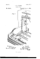
- Figure 1 is a perspective detail view, parts being broken away, of one end of an upright piano embodying my invention
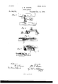
- Fig. 2 a detail view showing the counter-balance applied to the key and the counterbalance-rail
- Fig. 3 a detail view of the inner end of the .key, showing the means for varying the position of the striker
- Fig. 4 a detail view showing the connection between the pedal-rod and the rocker-rail
- l ig. 5 a detail perspective view of the sliding stop and the key-block separated, showing the relative position of each.
- 1 is the piano-block, to which the ends of the strings are secured; 2 the bridge; 3, the string; 4, the hammer; 5, the hammer-stem; (5, the hammer-lnitt; T, the bridle and guide; 8, the check; 9, the jack; lo, the bridle-support; ll, the whip; 12,the sticker; l3,thelifting-rocker; 14, the key; in, the counter-balance; '17, the counterbalancerail; 18, the hinge which rail swings upon; 1!), the keyframe; 20, the rocker-rail; Bl, the hinge on which the rocker-rail swings; 2:2, thcbase end of rocker-rail, which is enlarged so as to have the sliding wedge-sha 'ied stop-piece 31 slide under to hold up said rail, as is seen in 22,
- the operation of the device is as follows: 011 depressing the key it throws the hammer forward.
- the tilting rocker 13 on the key being in position to move with the key when struck is as if the key and rocker 13 were solid, because in this instance the relative arrangement of the parts is such that the rocker does not work at the joint at ll, but lies on the key from the joint 41 back to the rear end of the key, the counter-balance under the front end of the key being at rest and not making any extra weight on the key that would lessen the resistance to the touch more than ordinarily, as the counterbalance 16 is on a balance over the balance-rail 17. This makes no change in the action or the key, as it now represents the full piano.
- balance-rail 17 leaves its position half-way between the ends of the counter-balance, and nears the fulcrum 57, traveling from O to O on counter-balance 16, Fig. 2, thus increasing the resistance to the touch on the key while the hammers are up toward the strings.
- the counter-balance can be made to act with greater or less force'on the key, according to the position of the counterbalance-rail, thereby producing a graded touch.
- the three rails 17, 20, and 30 move at the same time as the weight is taken off the key by the hammers ascending toward the wires, the weight coming gradually on the outer or free end of the counter-balance.
- All the liftingrocker accomplishes is to have the jack follow up close to the butts of the hammer to take up and prevent any motion between the end of the jack and the hammer-butt. IVhen it is desired to hold the hammer up near to the wires without keeping the foot. 011 the pedal, press down and in on the stop-lever 35, which will bring the parts in the position shown in Fig. 1-that is, the sliding stop 31 is pushed under the rail 22 and under the eccentric 25, which is pivoted to the pedalfrom the kerf 56.
- the inner end of the stop is bifurcated and provided with the wedge-shaped ends 23 and 24.
- the wedge 23 is under the rail 20 at 22.
- the wedge 2-1 is under the eccentric or cam 25.
- the stop in this position holds the hammer nearer the wires without the foot being on the pedal rod, preserving the perfect piano touch and the same dip of the keys and not changing anything in the action.
- I have a plan for increasing the weight of the key and its consequent resistance to the touch by simply disconnect ing the lever 34: from the soft pedal lever 26, as shown by the dotted lines, Fig. 1, 34 being disconnected from the long.
- lever 26 at the forked end by disengaging the projection 37 After disconnecting lever 31 from the lever 26 a continued movement of the lever 31 in a downward direction will turn the counterbalance-rail 17 about its hinge and change its position relative to the counter balance, thus varying the resistance to the touch independently of the pedal.
Landscapes
- Physics & Mathematics (AREA)
- Engineering & Computer Science (AREA)
- Acoustics & Sound (AREA)
- Multimedia (AREA)
- Electrophonic Musical Instruments (AREA)
Description
2 Sheets--Sheet L (No Model.)
J. W. COOPER.
PIANO ACTION.
No. 394,251. Patented Dec. 11, 1888.
N4 PETERS. PhuRo-Liihcgnphen Washington. n.
(No Model.) 2 Sheets-Sheet 2.
Y J. W. COOPER. 4
PIANO ACTION.
Patented Dec. 11, 1888.
'.llllllllllllliliiiiilllllliiiilimfifill meiiamum .IIIllllllIllllllllIllllllllllllllllllllIlllllllllllllllll m'fzz'im. g) X f 12 2m f:
UNITED STATES PATENT Erica JOHN TV. COOPER, OF ATLANTA, GEORGIA.
PIANO-ACTION.
SPECIFICATION forming part of Letters Patent No. 394,251, dated December 11, 1888.
Application filed November 10, 1887. Serial No. 254,779. (No model.)
.act description of the invention, such as will enable others skilled in the art to which it appertains to make and use the same, reference being had to the accompanying drawings, and to the letters and figures of reference marked thereon, which form a part of this specification.
This invention relatesto piano-actions, and has a twofold obj ect-first, to vary the resistance of the keys to the touch by a weight connected with the keys, and having a shifting fulcrum, without changing the dip of the keys; second, to modulate the sound without .muftling the tone, and at the same time preserve the touch and dip of the key.
The resistance of the keys of a piano can .be readily adapted to the touch of any performer by a simple movement of the lever, and a performer having weak fingers can strengthen them by increasing the resistance of thekeys while practicing. The sound can .be quickly moderated without muffiing the tone, and independently of the pedal. The
throw of the hammer, when adjusted, can be fixed for any length of time and can be changed as often as required, and can be fur ther modified by the pedal, if necessary, provided the mechanism has not been adjusted to the limit at which it will give the softest sound.
The improvement consists in the novel features and peculiar construction and combination of parts, which will be more particularly hereinafter set forth and claimed, and shown .in the annexed drawings, in which Figure 1 is a perspective detail view, parts being broken away, of one end of an upright piano embodying my invention; Fig. 2, a detail view showing the counter-balance applied to the key and the counterbalance-rail; Fig. 3, a detail view of the inner end of the .key, showing the means for varying the position of the striker; Fig. 4, a detail view showing the connection between the pedal-rod and the rocker-rail; l ig. 5, a detail perspective view of the sliding stop and the key-block separated, showing the relative position of each.
Similar-letters and figures refer to corresponding parts in the several views.
1 is the piano-block, to which the ends of the strings are secured; 2 the bridge; 3, the string; 4, the hammer; 5, the hammer-stem; (5, the hammer-lnitt; T, the bridle and guide; 8, the check; 9, the jack; lo, the bridle-support; ll, the whip; 12,the sticker; l3,thelifting-rocker; 14, the key; in, the counter-balance; '17, the counterbalancerail; 18, the hinge which rail swings upon; 1!), the keyframe; 20, the rocker-rail; Bl, the hinge on which the rocker-rail swings; 2:2, thcbase end of rocker-rail, which is enlarged so as to have the sliding wedge-sha 'ied stop-piece 31 slide under to hold up said rail, as is seen in 22,
23, 2i, and 2o, soft-pedal lever; 27, pedalrod; 28, hammer-rail castings; 20, a section of the action-bracket; 30, the hammer-rail; 3l,the sliding stop 32, the key-block; 33, the casting with slots for levers to work through; 3i, the detachable lever; 35, the stop-lever; 36, the casting attached to counterbalancerail and connected to lever Si; 37, a projection cast on lever 3i to enter into one end of soft-pedal lever26 at forked end. 38 is where the stop-lever enters into sliding stop 31 at hole 39; 40, slot in casting 33 on key-block for stop-lever 35 to go through.
The operation of the device is as follows: 011 depressing the key it throws the hammer forward. The tilting rocker 13 on the key being in position to move with the key when struck is as if the key and rocker 13 were solid, because in this instance the relative arrangement of the parts is such that the rocker does not work at the joint at ll, but lies on the key from the joint 41 back to the rear end of the key, the counter-balance under the front end of the key being at rest and not making any extra weight on the key that would lessen the resistance to the touch more than ordinarily, as the counterbalance 16 is on a balance over the balance-rail 17. This makes no change in the action or the key, as it now represents the full piano. Now when we put on the soft pedal, by pressing upon the pedal (not shown) it throws up the pedal-rod 27, which raises the hammerrail 30, carrying the hammer up closer to the string and shortening its stroke, and at the same time the rockerrail 20 is carried up by a small pedal-rod, 55, taking hold of the middle of the rocker-rail, as shown most clearly in Fig. 4, raising the series of rockers at the same time the hanr mers are being raised up. The rocker, as will be seen, raises the sticker, which, being connected with the whip 11 in the action, and whip being connected with the jack 9, follows up the hammer; but as said rocker would not raise up the sticker, whip, and jack when the hammers rise up, then in that case there would be a space between the jack and hammer-butt. Now when the hammer-rail rises and the jack follows up the hammer-butt, the gravity of these parts is taken off the hammer to a great extent, as its rear end is raised in almost a perpendicular position. In this case the key is left, comparatively speaking, very light, as all or nearly all the weight is removed therefrom, and to compensate for this removal of weight, so as to preserve a uniform touch on the key, I found it necessary to substitute a counter-balance. Now when the hammer-rail and rocker-rail carry up the hammer, at the same time the counterbalance-rail is raised by the lever 26, which is raised or operated on by the pedal-rod 27, connected at 50 with the lever 26 and pivoted at 51, and then being connected with the lever 34 by having the projection 37 fitted into a slot or kerf, 56, in the end of long lever 26. The counterbalance-rail brings into operation the counter-balance 16, and counterbalancerail changes its position, as shown in Fig. 2, balance-rail 17 leaves its position half-way between the ends of the counter-balance, and nears the fulcrum 57, traveling from O to O on counter-balance 16, Fig. 2, thus increasing the resistance to the touch on the key while the hammers are up toward the strings. The counter-balance can be made to act with greater or less force'on the key, according to the position of the counterbalance-rail, thereby producing a graded touch. The three rails 17, 20, and 30 move at the same time as the weight is taken off the key by the hammers ascending toward the wires, the weight coming gradually on the outer or free end of the counter-balance. All the liftingrocker accomplishes is to have the jack follow up close to the butts of the hammer to take up and prevent any motion between the end of the jack and the hammer-butt. IVhen it is desired to hold the hammer up near to the wires without keeping the foot. 011 the pedal, press down and in on the stop-lever 35, which will bring the parts in the position shown in Fig. 1-that is, the sliding stop 31 is pushed under the rail 22 and under the eccentric 25, which is pivoted to the pedalfrom the kerf 56.
rod at 54. The inner end of the stop is bifurcated and provided with the wedge-shaped ends 23 and 24. The wedge 23 is under the rail 20 at 22. The wedge 2-1 is under the eccentric or cam 25. The stop in this position holds the hammer nearer the wires without the foot being on the pedal rod, preserving the perfect piano touch and the same dip of the keys and not changing anything in the action. In addition to a perfect soft pedal I have a plan for increasing the weight of the key and its consequent resistance to the touch by simply disconnect ing the lever 34: from the soft pedal lever 26, as shown by the dotted lines, Fig. 1, 34 being disconnected from the long. lever 26 at the forked end by disengaging the projection 37 After disconnecting lever 31 from the lever 26 a continued movement of the lever 31 in a downward direction will turn the counterbalance-rail 17 about its hinge and change its position relative to the counter balance, thus varying the resistance to the touch independently of the pedal.
Having thus described my invention, what I claim, and desire to secure by Letters Patent, 1s
1. In a piano-action, the combination, with the key having a lifting-rocker and the r0 ckerrail, of the sliding stop having a wedgeshaped end, and means for moving the stop, whereby the wedge-shaped end is projected under the rocker-rail, substantially as described.
2. The combination, with the key, the lifting-rocker, and the rocker-rail, of the counter-balance pivotally connected with the key, the counterbalanc'erail, and means for moving the rocker-rail and the counterbalancerail, substantially as set forth,- for the purpose described.
3. The combination, with the key and the counter-balance, of the counterbalance-rail and means for moving the counterbalancerail, whereby the fulcrum of the counter-balance is changed to vary the resistance of the key to the touch.
at. The combination, with the string, the hammer-rail, and the pedal-rod, of the cam 25 and the sliding stop adapted to be projected within the path of the cam, substantially as described, for the purpose specified.
5. The combination of the hammer-rail, the pedal-rod, the pedal-lever, the key, the counter-balance, the counterbalance-rail, and the lever 34, connecting the pedal-lever and the counterbalance rail, substantially as described.
6. The combination of the hammer-rail, the pedal-rod, the cam, the pedal-lever 26, the key, the counter-balance, the counterbalancerail, the lever 34:, and the sliding stop 31, adapted to be projected in the path of the cam 25, substantially as described, for the purpose set forth.
7. The combination of the key, the coun- In testimony WhereofI affixmy signature in tor-balance, the counterbalance-rail, the hampresence of two Witnesses. nier-rail, the pedal-rod, the pedal-lever 26, having a kerf in its outer end, and the lever 7 JOHN \V. COOPER. 5 34, having the projection 37 interposed between and adapted to connect and disconnect Vitnesses: the lever 26 and balance-rail, substantially as R. A. HALLIDAY, and for the purpose described. HARRY KROUSE.
Publications (1)
| Publication Number | Publication Date |
|---|---|
| US394251A true US394251A (en) | 1888-12-11 |
Family
ID=2463220
Family Applications (1)
| Application Number | Title | Priority Date | Filing Date |
|---|---|---|---|
| US394251D Expired - Lifetime US394251A (en) | Piano-action |
Country Status (1)
| Country | Link |
|---|---|
| US (1) | US394251A (en) |
-
0
- US US394251D patent/US394251A/en not_active Expired - Lifetime
Similar Documents
| Publication | Publication Date | Title |
|---|---|---|
| US394251A (en) | Piano-action | |
| US527533A (en) | Martin h | |
| US608177A (en) | Piano action | |
| US498523A (en) | Pianoforte-action | |
| US323632A (en) | Piano-action | |
| US308415A (en) | Leonard kustner | |
| US767100A (en) | Piano damper-action. | |
| US917994A (en) | Zither-piano. | |
| US619964A (en) | Piano-action and touch-regu lator therefor | |
| US1082895A (en) | Piano-action. | |
| US468918A (en) | Piano-action | |
| US794515A (en) | Pianissimo device. | |
| US560247A (en) | weser | |
| US294004A (en) | Piano action | |
| US780944A (en) | Piano damper-action. | |
| US2523A (en) | Mode op constructing shifting- movements for square or horizontal | |
| US165503A (en) | Improvement in damper mechanisms for piano-fortes | |
| US614340A (en) | Attachment for pianos | |
| US819556A (en) | Action for stringed musical instruments. | |
| US453938A (en) | Piano-forte action | |
| US228912A (en) | mailing | |
| US348111A (en) | Piano-action | |
| US232346A (en) | Upright piano-forte | |
| US4109A (en) | Samuel k | |
| US599585A (en) | becker |