US393003A - Boot-treeing machine - Google Patents
Boot-treeing machine Download PDFInfo
- Publication number
- US393003A US393003A US393003DA US393003A US 393003 A US393003 A US 393003A US 393003D A US393003D A US 393003DA US 393003 A US393003 A US 393003A
- Authority
- US
- United States
- Prior art keywords
- boot
- head
- tree
- ring
- machine
- Prior art date
- Legal status (The legal status is an assumption and is not a legal conclusion. Google has not performed a legal analysis and makes no representation as to the accuracy of the status listed.)
- Expired - Lifetime
Links
Images

Classifications
-
- A—HUMAN NECESSITIES
- A43—FOOTWEAR
- A43D—MACHINES, TOOLS, EQUIPMENT OR METHODS FOR MANUFACTURING OR REPAIRING FOOTWEAR
- A43D95/00—Shoe-finishing machines
- A43D95/02—Machines for treating or smoothing shoe uppers to remove wrinkles, folds, or the like
Definitions
- FIG. 1 represents a central longitudinal section of the machine, showing one of the trees and its shoe in elevation.
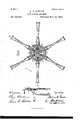
- Fig. 2 represents a horizontal section on the line A B in Fig. 1, as seen from below said line; and Fig. 8 represents a similar section on said line A B, as seen from above such line.
- Fig. 4 represents a detail sectional view ofthe automatic expansion device for the tree; and
- Fig. 5 represents an end view of the same, as seen from Z in Fig. 4.
- Fig. 6 represents a detail sectional view of the treadle-locking mechanism.
- the frame or standard of the machine is preferably made in two parts-namely, a lower one, a, adapted to rest on the iioor, and an upper one, b, that is made vertically adjustable within the upper end of the lower one, as shown in Fig. l, so as to enable the machine to be raised or lowered to suit the requirements of the operator, and after such upper frame part is adj usted relative to the lower one it is secured to the latter by means of screws or other suitable fastening device.
- annular ring, c having at one place of its interior portion a recess, c', (shown in Figs. l and 2,) for a purpose, as will hereinafter be described.
- c is the central hub of the ring c, and to it is secured the vertical pin or shaft C, on which is journaled the tree carrying head D, as shown in Figs. 1 and 2, which head is provided with two or more radiallyprojecting sockets, d d, for receiving the shanks of the' boottrees, as shown in Figs. 1, 2, and 4.
- the rod e By depressing the treadle-lever f, the rod ewill be drawn downward against the influence of the spring E sufficiently to cause its upper end to be disengaged from that one of the locking-notches cl inthe head D, in which it was lockcd,when Vthe said head with its trees and shoes held thereon may be turned freely around a part of a revolution until the next locking-notch,d,in the series reaches the locking-rod e,w.hen the latter will automatically bc forced upward into such notch by the influence of the spring E, the operator in the meantime having removed his foot from the treadle-lever f, and sol on.
- g represents the tree-body provided with a cylindrical shank, g', loosely inserted in the socket d of the head D, in which it maybe turned around during the operation of the machine.
- g3 is the usual forward part of the tree, secured to or forming a part of the body g
- g4t is the expansible back part ofthe tree, as usual.
- the back portion, g is actuated to and from the front portion, g3, by means of the rod g5, arranged within the tree, as usual, and connected in its outer end to a slotted link, g, or equivalent device, pivoted to the part g3 or its con nections, said rod g5 being automaticallyforced roo outward by theinfluence of a spring, g7,(shown in Figs. l and 4,) to move the part g toward the part g3 to enable the finished boot or shoe to be removed from the tree and to place another one thereon.
- each expansion-rod g5 To the inner ⁇ end of each expansion-rod g5 is secured, in a suitable manner, a spindle, I, arranged within a recess, h, in the block H, to the lower portion of which is journaled the roller h on a pin, h', as shown in Figs. 1, 2, 3, and 4.
- the said roller his automatically forced outward against the interior of the ring c by the iniiuencc of the spring 97 on the expansionrod g5, as shown in said Figs. 1, 2, 3, and 4.
- the operator stands at the place marked Yin Fig. 2, and an attendant stands at the place marked X in the said figure.
- the boot-tree at Y is automatically expanded by the rods gi being moved toward the center of the ring c by the agency of the rollers h h riding and resting on the cylindrical interior surface of the ring c, as shown in Figs. 1, 2, and 3, by which the boots or shoes on such expanded trees arevproperly stretched on the latter.
- the operator at Y has treed the boot or shoe in front of him, he depresses the treadle j', and thus liberates the head D from the standard and swings said head and its trees a partial revolution in the direction shown by arrows in Figs.
- rlhe tension of the spring i is regulated by means of' a set-screw, i4, screwed through the end of the spindle I against the key i, as shown in said figures.
- 7c is a ring secured to the rear of the block H, and it has on the top an opening, 7c', of a size sufficient to enable the key i to pass through it, by which arrangement the tree may be removed, when so desired, simply by unscrewing the set-screw i* and introducing a h ook or other suitable or convenient tool through one of the perforations d3 in the head D, and by this means withdrawing the said key i from the slotted spindle I.
- the ring 7c serves to prevent the key i from dropping out of the slotted spindle I during the rotation of the tree around its axis while the treeing process takes place.
- a boot or shoe treeing machine a stationary hollow base, a, and a vertically-adj ustable non-rotating standard, b, in combination with a rotary head, D, and a series of rotary boot or shoe trees journaled in said head, substantiallyin a manner'and for vthe purpose Set forth.
- a stationary ring, c having on its interior portion a recess, c', combined with a tree-carrying head, D, pivoted to said ring or its connections, and a series of expansive boot-trees j ournalcd in sockets on said heads and having their spring-pressed expansion-rods connected to rollers adapted to be actuated by said ring for the purpose of automatically expanding and contracting the trees, substantially as and for the purpose set forth.
- the stationary ring c having on its interior the recess c', and the rotary head D, having journaled to it a series of expansive trees with springpressed expansion-rods g5, combined with the blocks H, yieldingly and adj ustably secured to said expansion-rods and provided with rollers h, adapted to lie in contact with and to be actuated by the ring c and its recess c', substantially in a manner and for the purpose set forth.
- a boot or shoe treeing machine In a boot or shoe treeing machine, a standard or frame, a cani-shaped ring secured to it, a rotatable head journaled to said ring or standard, a locking device for securing said head and standard or ring together, and a series of expansive trees journaled to said head, and means,substantially as described, for automatically expanding and contracting the boottrees during the rotation of the tree-carrying lfieail, substantially as and for the purpose set ort 5.
Landscapes
- Footwear And Its Accessory, Manufacturing Method And Apparatuses (AREA)
Description
2 Sheets-Sheet '1.
,(No Model.)
A. B. POWLBR. BOOT TRBBING MACHINE.
,003.l Patented Nov. Z0, 1.888.
2 S-heetsmheet 2.
(No Model.)
A. 13.P0WLER.V BOOT 4TEEINGA MACHINE.
. Ptvented Nov. 20, 1888.8
" lNirnn Srn'rns PATENT rtree.
ALFRED B. FOVLER, OF EXETER, NEI/V HAMPSHIRE, ASSIGNORv TO OLIVER A. MILLER, OF BROOKTON, MASSACHUSETTS.
BOOT-TRI SPECIFICATION forming part of Letters Patent No. 393,003, dated November 20, 1888.
Application filed June 26, 1888. Ser-inl No. 278,252. (No model.)
.To aZZ whom, it may concern:
Beit known that I, ALFRED B. FowLnR, a citizen'of the United States, and a resident of Exeter, in the county of Rockingham and State of New Hampshire, have invented new and useful Improvements in Treeing Machines, of which the following, taken in connection with the accompanying drawings, is a specification.
This invention relates to improvements in machines for treeing boots or shoes, and it is? carried out as follows, reference being had to the accompanying drawings, wherein- Figure 1 represents a central longitudinal section of the machine, showing one of the trees and its shoe in elevation. Fig. 2 represents a horizontal section on the line A B in Fig. 1, as seen from below said line; and Fig. 8 represents a similar section on said line A B, as seen from above such line. Fig. 4 represents a detail sectional view ofthe automatic expansion device for the tree; and Fig. 5 represents an end view of the same, as seen from Z in Fig. 4. Fig. 6 represents a detail sectional view of the treadle-locking mechanism.
Similar letters refer to similar parts Wherever they occur on the different parts of the drawings. j
The frame or standard of the machine is preferably made in two parts-namely, a lower one, a, adapted to rest on the iioor, and an upper one, b, that is made vertically adjustable within the upper end of the lower one, as shown in Fig. l, so as to enable the machine to be raised or lowered to suit the requirements of the operator, and after such upper frame part is adj usted relative to the lower one it is secured to the latter by means of screws or other suitable fastening device.
To the upper end of the frame or standard b, I secure an annular ring, c, having at one place of its interior portion a recess, c', (shown in Figs. l and 2,) for a purpose, as will hereinafter be described.
cis the central hub of the ring c, and to it is secured the vertical pin or shaft C, on which is journaled the tree carrying head D, as shown in Figs. 1 and 2, which head is provided with two or more radiallyprojecting sockets, d d, for receiving the shanks of the' boottrees, as shown in Figs. 1, 2, and 4.
On the circumference of the head D, between its sockets d, are made vertical notches or locking-recesses d d', adapted to receive the upper end of the spring-pressed locking-rod @that is guided in a bearing on the ring c or other stationary part of the machine, as shown in Figs. 3 and 6, and normally held upward in a locked position relative to the head D by the induence of a spring, E, or equivalent device. To the lower end of the rod e is adjustably secured the downwardly-projecting rod e', the lower end of which is connected to the treadlelever f, that is pivoted atf to the frame or standard a. By depressing the treadle-lever f, the rod ewill be drawn downward against the influence of the spring E sufficiently to cause its upper end to be disengaged from that one of the locking-notches cl inthe head D, in which it was lockcd,when Vthe said head with its trees and shoes held thereon may be turned freely around a part of a revolution until the next locking-notch,d,in the series reaches the locking-rod e,w.hen the latter will automatically bc forced upward into such notch by the influence of the spring E, the operator in the meantime having removed his foot from the treadle-lever f, and sol on.
In connection with the machine I use anumber' of boot-trees equal in number to the sockets d in the head D. Each of these trees is of the usual expansible construction and need not here minutely be described, it being sufficient for the purpose to state that g represents the tree-body provided with a cylindrical shank, g', loosely inserted in the socket d of the head D, in which it maybe turned around during the operation of the machine. A setscrew, d, screwed through the socket d and having its inner end projecting in an annular groove, g, on the shank g', serves to connect the latter to the said socket d, as shown in Figs. 1 and 4. g3 is the usual forward part of the tree, secured to or forming a part of the body g, and g4t is the expansible back part ofthe tree, as usual.
The back portion, g, is actuated to and from the front portion, g3, by means of the rod g5, arranged within the tree, as usual, and connected in its outer end to a slotted link, g, or equivalent device, pivoted to the part g3 or its con nections, said rod g5 being automaticallyforced roo outward by theinfluence of a spring, g7,(shown in Figs. l and 4,) to move the part g toward the part g3 to enable the finished boot or shoe to be removed from the tree and to place another one thereon.
I wish to state that I do not claim tlic cxpansive tree, as shown, nor the mechanism, as described, for its operation as my invention, as such is well known in the art, and any of the usual expansive trees may be used with my machine without departing from the cssence of my invention.
In connection with the expansive trees I use an automatic mechanism for expanding and contracting them during the intermittent rotary motion of the head D, and it is constructed as follows:
To the inner` end of each expansion-rod g5 is secured, in a suitable manner, a spindle, I, arranged within a recess, h, in the block H, to the lower portion of which is journaled the roller h on a pin, h', as shown in Figs. 1, 2, 3, and 4. The said roller his automatically forced outward against the interior of the ring c by the iniiuencc of the spring 97 on the expansionrod g5, as shown in said Figs. 1, 2, 3, and 4. During the operation oi' the machine the operator stands at the place marked Yin Fig. 2, and an attendant stands at the place marked X in the said figure.
rIhe boot-tree opposite to X is automatically contracted by the roller h being forced into the recess c on the interior of the cylindrical ring' c by the influence of the spring g?, as shown in Figs. l, 2, 3, and 4, thus enabling the attendant at X to remove the finished shoe and to place another one on the tree.
The operator at Y in the meantime performs the treeing operation on the boot or shoe directly in front of him, the head D during such operation being locked firmly in position to the frame or standard of the machine by the locking mechanism hereinabove described.
The boot-tree at Y, as well as all the other trees in the series except the one at X, is automatically expanded by the rods gi being moved toward the center of the ring c by the agency of the rollers h h riding and resting on the cylindrical interior surface of the ring c, as shown in Figs. 1, 2, and 3, by which the boots or shoes on such expanded trees arevproperly stretched on the latter. When the operator at Y has treed the boot or shoe in front of him, he depresses the treadle j', and thus liberates the head D from the standard and swings said head and its trees a partial revolution in the direction shown by arrows in Figs. 2 and 3, until the next tree in the series is brought opposite to him, when the head D is again locked in position, another boot treed, and the finished boot at X removed by the attendant and replaced by another one to be treed, and so on; but it is desirable that during the treeing operation any stretching of theleather that may occur should be automatically taken up 5 and for this purpose I interpose between the bottomof the recess 7L in the block II and a collar, i, on the spindle I a coiled or rubber spring, i, (shown in Figs. I and 4,) the said collar/t being held in position on the spindle I by means of a key, i", passing through a slot, i, in the spindle I, as shown in Figs. 1 and 4.
rlhe tension of the spring i is regulated by means of' a set-screw, i4, screwed through the end of the spindle I against the key i, as shown in said figures.
7c is a ring secured to the rear of the block H, and it has on the top an opening, 7c', of a size sufficient to enable the key i to pass through it, by which arrangement the tree may be removed, when so desired, simply by unscrewing the set-screw i* and introducing a h ook or other suitable or convenient tool through one of the perforations d3 in the head D, and by this means withdrawing the said key i from the slotted spindle I. The ring 7c serves to prevent the key i from dropping out of the slotted spindle I during the rotation of the tree around its axis while the treeing process takes place.
Having thus fully' described the nature, construction, and operation of my invention, I
.wish to secure by Letters Patent and claim- 1. In a boot or shoe treeing machine, a stationary hollow base, a, and a vertically-adj ustable non-rotating standard, b, in combination with a rotary head, D, and a series of rotary boot or shoe trees journaled in said head, substantiallyin a manner'and for vthe purpose Set forth.
2. In a boot or shoe treeing machine, a stationary ring, c, having on its interior portion a recess, c', combined with a tree-carrying head, D, pivoted to said ring or its connections, and a series of expansive boot-trees j ournalcd in sockets on said heads and having their spring-pressed expansion-rods connected to rollers adapted to be actuated by said ring for the purpose of automatically expanding and contracting the trees, substantially as and for the purpose set forth.
3. In a boot or shoe treeing machine,the stationary ring c, having on its interior the recess c', and the rotary head D, having journaled to it a series of expansive trees with springpressed expansion-rods g5, combined with the blocks H, yieldingly and adj ustably secured to said expansion-rods and provided with rollers h, adapted to lie in contact with and to be actuated by the ring c and its recess c', substantially in a manner and for the purpose set forth.
4. In a boot or shoe treeing machine,a standard or frame, a cani-shaped ring secured to it, a rotatable head journaled to said ring or standard, a locking device for securing said head and standard or ring together, and a series of expansive trees journaled to said head, and means,substantially as described, for automatically expanding and contracting the boottrees during the rotation of the tree-carrying lfieail, substantially as and for the purpose set ort 5. In a boot or shoe treeing machine, a sta- IOO tionary cam-shaped ring, c c', a boot-tree-oarcombined substantially as and for the purpose rying head, D, journaled to said ring` or its set forth.
connections and having perforations d3, as de- In testimony whereof Ihave signed my name scribed, combined with the expansive trees to this specication,in the presence of two sub- 15 5 journaled tosaidheadandhavingtheir springsoribing Witnesses, on this 28d day of J une,
pressed expansion-rods g5 connected to spring- A. D. 1888.
pressed spindles I, arranged within recesses in theroller-carrying blocks H, the slitted rings k k', secured to said blocks H, and the set- Witnesses: to screws i* for regulating the tension of the O. A. MILLER,
springs z", and the keys i, all arranged and H. STORER BARRY.
ALFRED B. FOWLER.
Publications (1)
| Publication Number | Publication Date |
|---|---|
| US393003A true US393003A (en) | 1888-11-20 |
Family
ID=2461974
Family Applications (1)
| Application Number | Title | Priority Date | Filing Date |
|---|---|---|---|
| US393003D Expired - Lifetime US393003A (en) | Boot-treeing machine |
Country Status (1)
| Country | Link |
|---|---|
| US (1) | US393003A (en) |
-
0
- US US393003D patent/US393003A/en not_active Expired - Lifetime
Similar Documents
| Publication | Publication Date | Title |
|---|---|---|
| US393003A (en) | Boot-treeing machine | |
| US599773A (en) | Treeing-machine for boots or shoes | |
| US442033A (en) | Boot-treeing machine | |
| US142756A (en) | Improvement in machines for trimming and burnishing the edges of boots and shoes | |
| US1005352A (en) | Machine for brushing edges of boot and shoe soles. | |
| US553948A (en) | winkley | |
| US891912A (en) | Machine for supporting shoe-uppers. | |
| US132957A (en) | Improvement in holding devices for heel trimming and burnishing machines | |
| US392715A (en) | Heel-burnishing machine | |
| US503475A (en) | Heel-trimming machine | |
| US836862A (en) | Stitch-indenting machine. | |
| US764335A (en) | Jack for boots or shoes. | |
| US543147A (en) | clark | |
| US589732A (en) | Machine for shaping boots or shoes | |
| US385702A (en) | Heel-burnishing machine | |
| US418694A (en) | Simon a | |
| US391001A (en) | Lasting and sole-laying machine | |
| US283381A (en) | Assigxtob of one-half | |
| US438997A (en) | fowler | |
| US221954A (en) | Improvement in boot and shoe heel burnishing machines | |
| US357741A (en) | Heel-trimming machine | |
| US361628A (en) | Chaeles e | |
| US153274A (en) | Improvement in boot-blacking machines | |
| US447965A (en) | mebklen | |
| US1087423A (en) | Treeing-stand. |