US3927768A - Magazine rack - Google Patents
Magazine rack Download PDFInfo
- Publication number
- US3927768A US3927768A US321733A US32173373A US3927768A US 3927768 A US3927768 A US 3927768A US 321733 A US321733 A US 321733A US 32173373 A US32173373 A US 32173373A US 3927768 A US3927768 A US 3927768A
- Authority
- US
- United States
- Prior art keywords
- members
- spine
- rack
- pair
- presser member
- Prior art date
- Legal status (The legal status is an assumption and is not a legal conclusion. Google has not performed a legal analysis and makes no representation as to the accuracy of the status listed.)
- Expired - Lifetime
Links
- 230000007812 deficiency Effects 0.000 description 2
- 238000004519 manufacturing process Methods 0.000 description 2
- 239000000463 material Substances 0.000 description 2
- 238000010276 construction Methods 0.000 description 1
- 230000002950 deficient Effects 0.000 description 1
- 238000001514 detection method Methods 0.000 description 1
- 238000006073 displacement reaction Methods 0.000 description 1
- 238000007689 inspection Methods 0.000 description 1
- 230000004048 modification Effects 0.000 description 1
- 238000012986 modification Methods 0.000 description 1
- 238000010422 painting Methods 0.000 description 1
- 238000010186 staining Methods 0.000 description 1
- 238000006467 substitution reaction Methods 0.000 description 1
- 239000002023 wood Substances 0.000 description 1
Images

Classifications
-
- A—HUMAN NECESSITIES
- A47—FURNITURE; DOMESTIC ARTICLES OR APPLIANCES; COFFEE MILLS; SPICE MILLS; SUCTION CLEANERS IN GENERAL
- A47F—SPECIAL FURNITURE, FITTINGS, OR ACCESSORIES FOR SHOPS, STOREHOUSES, BARS, RESTAURANTS OR THE LIKE; PAYING COUNTERS
- A47F1/00—Racks for dispensing merchandise; Containers for dispensing merchandise
- A47F1/04—Racks or containers with arrangements for dispensing articles, e.g. by means of gravity or springs
- A47F1/12—Racks or containers with arrangements for dispensing articles, e.g. by means of gravity or springs dispensing from the side of an approximately horizontal stack
- A47F1/121—Racks or containers with arrangements for dispensing articles, e.g. by means of gravity or springs dispensing from the side of an approximately horizontal stack made of tubes or wire
Definitions
- A47f H06 Field of Search 211/49 R, 49 D, 50, 51, ABSTRACT 211/52, 53, 54, 106, 181; 312/42, 50, 61, 71
- a Magazine Rack having a U-shaped back, retangular support members and a spine secured to said support
- a substantially U-shaped presser member is UNTTED STATES PATENTS pivotally connected to cross members secured to the 272,000 2/1883 Umbdenstock 211/106 Spine and Sprmg based agamst the from of the 370,563 9/1887 Simmons spme- 579,566 3/1897 Drenning 211/51 1 Claim, 4 Drawing Figures U.S. Patfint Dec.23, 1975 Sheet20f2 3,927,768
- This invention relates to a rack and more specifically to a magazine rack in which magazines are sturdily held in position.
- Racks which are constructed of bulky wood-type or other opaque materials, tend to obstruct views. These racks are also less durable because of the extensive use of nails, screws, and similar devices prone to displacement. Conventional wooden racks are more costly in production due to the extra materials and work involved in the staining, painting and finishing of the wood to compliment the decor of a particular room. But as aforementioned, the primary deficiency of the conventional rack is the lack of a means whereby contents may be held in a secure, upright, orderly position. The lack of this means not only hinders the orderly placement and removal of the racks contents, but permits the magazines to fall toward the rear of the rack.
- the invention provides a rack which is light-weight, and capable of a variety of placement positions in a room, such as hanging on a wall, placing on a table or placing on a floor. Further, the invention provides a rack of greater durability and a means whereby magazines can be positioned and secured in an orderly upright fashion in the front of the rack allowing for easy detection of the particular magazine desired with out disrupting the order of the other items therein placed.
- Still further objects of this invention reside in a rack whereby the user may insert a magazine at the front of the rack.
- This invention is less cumbersome than conventional racks and is relatively inexpensive to manufacture.
- FIG. 1 is a perspective view of a preferred embodiment of a magazine rack constructed of rigid wire in accordance with the invention.
- FIG. 2 is a vertical sectional view taken along the plane of line 2-2 FIG. 1 illustrating part of the spine, the back and a down-biased spring connected to a follower member;
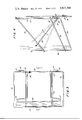
- FIG. 3 is a top view of the preferred embodiment showing follower member, a rectangular support member, the back, and the front;
- FIG. 4 is an entire cross-sectional view of FIG. 3 additionally showing a lower rectangular support member, the vase and the follower member pivotally connected to the spine.
- reference numeral 10 is used to generally designate a magazine rack having a rectangular support member 20 to which a U-shaped back is welded or otherewise attached.
- a wire spine 15 of integral construction has a pair of rear members 28 and 50 which extend downwardly from the rectangular support member 20.
- the spine is strengthened by two cross members including an upper cross member 34 and a lower cross member 32 parallel to each other and connecting across members 28 and 50.
- a substantial U-shaped presser member 38 having divergent wings 39 and 41 is pivotally connected to the lower cross member 32 and is engaged with at least one down-biased spring 36 which is mounted on upper cross member 34 and lower cross member 32.
- the spring 36 urges the substantial U-shaped member 38 to contact the two front members 56 and 57 of the spine 15, which are interconnected by connected members 50.
- the front members 56 and 57 are forwardly arcuate, and are connected to members 28 and 59 by members 52 and 54.
- a second rectangular support member 30 having its lowest side connecting to front member 56, and 57 and its highest side connecting to U-shaped member 22 and rear member 28 and 50.
- magazines are inserted by merely lifting the presser member 38. After the magazines are inserted, the presser member will hold the magazines securely and in an upright position firmly at the front of the rack. There will be no loose falling of individual magazines in the rack but all the magazines will be firmly urged by the presser member 38 toward the front of the rack. If a prospective purchaser were to remove a magazine for inspection, the magazine may be easily reinserted because of the forwardly arcuated top configuration of members 56 and 57.
- the spring 36 is disposed opposite the approximate location of the spines of the magazines to be displayed in the magazine rack.
- a plurality of the racks may be arranged against a supporting structure and held there by suitable fasteners extending through mounting plates 24.
- the racks may be manufactured in multiples as desired.
- a rack comprising a back, upper and lower rectangular wire support members connected to said back and extending downwardly and forwardly therefrom, said back including an upright U-shaped member having an open end closed by said upper support member,
- said spine including a pair of cross members, said presser member being pivotally mounted on one of said cross members, said presser member being located substantially inwardly of said spine and including two diverging wings at the front thereof. said wings being engageable with said spine,
- said spring means being disposed on said one of said cross members at one side thereof.
Abstract
A Magazine Rack having a U-shaped back, retangular support members and a spine secured to said support members. A substantially U-shaped presser member is pivotally connected to cross members secured to the spine and is spring biased against the front of the spine.
Description
" ted States Patent 1191 1111 3,927,768
fiohen Dec. 23, 1975 1 MAGAZINE RACK 996,421 6/1911 McCausland 211/51 1,038,474 9/1912 Back 211/51 [76] Inventor. Melv1nC0hen,58 He1ghts Road, 1,894,597 H1933 Murrayw H 21 V51 2,186,343 r 1/1940 Potts 211/51 [22] Filed, Jan 8 1973 3,326,388 6/1967 Zider 211/51 [211 Appl. No.: 321,733 Primary ExaminerRoy D. Frazier Assistant Examiner--Thomas J. Holko 52 US. (:1 211/49 1); 211/51; 211/106; Agen Goldfarb 211/181 r [51] Int. Cl. A47f H06 [58] Field of Search 211/49 R, 49 D, 50, 51, ABSTRACT 211/52, 53, 54, 106, 181; 312/42, 50, 61, 71 A Magazine Rack having a U-shaped back, retangular support members and a spine secured to said support [56] References Cited members. A substantially U-shaped presser member is UNTTED STATES PATENTS pivotally connected to cross members secured to the 272,000 2/1883 Umbdenstock 211/106 Spine and Sprmg based agamst the from of the 370,563 9/1887 Simmons spme- 579,566 3/1897 Drenning 211/51 1 Claim, 4 Drawing Figures U.S. Patfint Dec.23, 1975 Sheet20f2 3,927,768
FIG. 4
'1 MAGAZINE RACK BACKGROUND OF THE INVENTION l. Field of the Invention This invention relates to a rack and more specifically to a magazine rack in which magazines are sturdily held in position.
.2. Description of the Prior A Conventional magazine racks fulfill the object of being a receptacle for the placement of magazines, newspapers and sundry items. But the placement of these items hereto fore has been deficient because the receptacle has no means whereby these items may be maintained in an orderly upright position for easy withdrawal and replacement without flopping.
Racks, which are constructed of bulky wood-type or other opaque materials, tend to obstruct views. These racks are also less durable because of the extensive use of nails, screws, and similar devices prone to displacement. Conventional wooden racks are more costly in production due to the extra materials and work involved in the staining, painting and finishing of the wood to compliment the decor of a particular room. But as aforementioned, the primary deficiency of the conventional rack is the lack of a means whereby contents may be held in a secure, upright, orderly position. The lack of this means not only hinders the orderly placement and removal of the racks contents, but permits the magazines to fall toward the rear of the rack. Generally, those minority of racks in which it is possible to store items in some orderly fashion, are still limited because the magazines and such are stacked at the same height one behind the other, thus, obstructing the titles of the succeeding magazines. To pick out the disired item the whole stack must be examined. Therefore, it is desirable to have a magazine rack designed in such a way as to eliminate the aforementioned deficiencies of the conventional type magazine rack.
SUMMARY OF THE INVENTION Accordingly it is an object of the invention to provide a rack which is light-weight, and capable ofa variety of placement positions in a room, such as hanging on a wall, placing on a table or placing on a floor. Further, the invention provides a rack of greater durability and a means whereby magazines can be positioned and secured in an orderly upright fashion in the front of the rack allowing for easy detection of the particular magazine desired with out disrupting the order of the other items therein placed.
Still further objects of this invention reside in a rack whereby the user may insert a magazine at the front of the rack. This invention is less cumbersome than conventional racks and is relatively inexpensive to manufacture.
These together with the various ancillary objects and features which will become apparent to those artisnas possessing ordinary skill in the art and as the following description proceeds, are attained by this novel magazine rack a preferred embodiment shown in the accompanying drawings by way of example only wherein:
BRIEF DESCRIPTION OF THE DRAWING FIG. 1 is a perspective view of a preferred embodiment of a magazine rack constructed of rigid wire in accordance with the invention.
FIG. 2 is a vertical sectional view taken along the plane of line 2-2 FIG. 1 illustrating part of the spine, the back and a down-biased spring connected to a follower member;
FIG. 3 is a top view of the preferred embodiment showing follower member,a rectangular support member, the back, and the front;
FIG. 4 is an entire cross-sectional view of FIG. 3 additionally showing a lower rectangular support member, the vase and the follower member pivotally connected to the spine.
DETAILED DESCRIPTION OF THE INVENTION With continuing reference to the accompanying drawing wherein like reference numerals designate simular parts throughout the various views. reference numeral 10 is used to generally designate a magazine rack having a rectangular support member 20 to which a U-shaped back is welded or otherewise attached. A wire spine 15 of integral construction has a pair of rear members 28 and 50 which extend downwardly from the rectangular support member 20. The spine is strengthened by two cross members including an upper cross member 34 and a lower cross member 32 parallel to each other and connecting across members 28 and 50. A substantial U-shaped presser member 38 having divergent wings 39 and 41 is pivotally connected to the lower cross member 32 and is engaged with at least one down-biased spring 36 which is mounted on upper cross member 34 and lower cross member 32. The spring 36 urges the substantial U-shaped member 38 to contact the two front members 56 and 57 of the spine 15, which are interconnected by connected members 50. The front members 56 and 57 are forwardly arcuate, and are connected to members 28 and 59 by members 52 and 54.
A second rectangular support member 30 having its lowest side connecting to front member 56, and 57 and its highest side connecting to U-shaped member 22 and rear member 28 and 50.
In operation magazines are inserted by merely lifting the presser member 38. After the magazines are inserted, the presser member will hold the magazines securely and in an upright position firmly at the front of the rack. There will be no loose falling of individual magazines in the rack but all the magazines will be firmly urged by the presser member 38 toward the front of the rack. If a prospective purchaser were to remove a magazine for inspection, the magazine may be easily reinserted because of the forwardly arcuated top configuration of members 56 and 57. The spring 36 is disposed opposite the approximate location of the spines of the magazines to be displayed in the magazine rack.
A plurality of the racks may be arranged against a supporting structure and held there by suitable fasteners extending through mounting plates 24. Of course the racks may be manufactured in multiples as desired.
A latitude of modification change and substitution is intended in the foregoing disclosure, and in some instances some features ofthe invention will be employed without a corresponding use of other features.
What is claimed is:
l. A rack comprising a back, upper and lower rectangular wire support members connected to said back and extending downwardly and forwardly therefrom, said back including an upright U-shaped member having an open end closed by said upper support member,
nectedto said spine at the rear thereof, and spring means for urging said presser member against said spine at the front thereof, said spine including a pair of cross members, said presser member being pivotally mounted on one of said cross members, said presser member being located substantially inwardly of said spine and including two diverging wings at the front thereof. said wings being engageable with said spine,
said spring means being disposed on said one of said cross members at one side thereof.
Claims (1)
1. A rack comprising a back, upper and lower rectangular wire support members connected to said back and extending downwardly and forwardly therefrom, said back including an upright U-shaped member having an open end closed by said upper support member, a U-shaped spine open at the top including a pair of rear members extending downwardly from said upper support member and a pair of front members extending upwardly from a pair of members connecting said front and rear members and a connected member connecting said front members, said rear members being attached to the rear of said support members and said front members being attached to the front of said support members, said spine being located inwardly of said rectangular support members, and an upwardly and forwardly extending presser member pivotally connected to said spine at the rear thereof, and spring means for urging said presser member against said spine at the front thereof, said sPine including a pair of cross members, said presser member being pivotally mounted on one of said cross members, said presser member being located substantially inwardly of said spine and including two diverging wings at the front thereof, said wings being engageable with said spine, said spring means being disposed on said one of said cross members at one side thereof.
Priority Applications (1)
| Application Number | Priority Date | Filing Date | Title |
|---|---|---|---|
| US321733A US3927768A (en) | 1973-01-08 | 1973-01-08 | Magazine rack |
Applications Claiming Priority (1)
| Application Number | Priority Date | Filing Date | Title |
|---|---|---|---|
| US321733A US3927768A (en) | 1973-01-08 | 1973-01-08 | Magazine rack |
Publications (1)
| Publication Number | Publication Date |
|---|---|
| US3927768A true US3927768A (en) | 1975-12-23 |
Family
ID=23251792
Family Applications (1)
| Application Number | Title | Priority Date | Filing Date |
|---|---|---|---|
| US321733A Expired - Lifetime US3927768A (en) | 1973-01-08 | 1973-01-08 | Magazine rack |
Country Status (1)
| Country | Link |
|---|---|
| US (1) | US3927768A (en) |
Cited By (5)
| Publication number | Priority date | Publication date | Assignee | Title |
|---|---|---|---|---|
| US4146138A (en) * | 1978-01-18 | 1979-03-27 | Davis Dale W | Clamp on magazine rack |
| US5996812A (en) * | 1998-04-20 | 1999-12-07 | Seville Classics, Inc. | Organizer assembly |
| US20070068884A1 (en) * | 2005-09-23 | 2007-03-29 | Dipietro Dean | Napkin holder assembly |
| US20090258127A1 (en) * | 2008-04-15 | 2009-10-15 | Joshua Holtz | Container Rack of a Food Warmer and Method of Use |
| SE2151369A1 (en) * | 2021-11-08 | 2023-02-21 | Svenska Good Medical Ab | Wire frame holding system for packages comprising adjustable clamping means |
Citations (8)
| Publication number | Priority date | Publication date | Assignee | Title |
|---|---|---|---|---|
| US272000A (en) * | 1883-02-06 | Rack for advertising-cards | ||
| US370563A (en) * | 1887-09-27 | William amos simmons | ||
| US579566A (en) * | 1897-03-30 | Bag or paper holder | ||
| US996421A (en) * | 1911-01-07 | 1911-06-27 | Perkins C Mccausland | Bag-holder. |
| US1038474A (en) * | 1912-03-05 | 1912-09-10 | Arthur D Back | Bag-holder. |
| US1894597A (en) * | 1933-01-17 | Bag holder | ||
| US2186343A (en) * | 1938-03-28 | 1940-01-09 | William F Potts | Retainer for paper bags |
| US3326388A (en) * | 1965-03-10 | 1967-06-20 | Charles E Zidek | Article retaining rack |
-
1973
- 1973-01-08 US US321733A patent/US3927768A/en not_active Expired - Lifetime
Patent Citations (8)
| Publication number | Priority date | Publication date | Assignee | Title |
|---|---|---|---|---|
| US272000A (en) * | 1883-02-06 | Rack for advertising-cards | ||
| US370563A (en) * | 1887-09-27 | William amos simmons | ||
| US579566A (en) * | 1897-03-30 | Bag or paper holder | ||
| US1894597A (en) * | 1933-01-17 | Bag holder | ||
| US996421A (en) * | 1911-01-07 | 1911-06-27 | Perkins C Mccausland | Bag-holder. |
| US1038474A (en) * | 1912-03-05 | 1912-09-10 | Arthur D Back | Bag-holder. |
| US2186343A (en) * | 1938-03-28 | 1940-01-09 | William F Potts | Retainer for paper bags |
| US3326388A (en) * | 1965-03-10 | 1967-06-20 | Charles E Zidek | Article retaining rack |
Cited By (7)
| Publication number | Priority date | Publication date | Assignee | Title |
|---|---|---|---|---|
| US4146138A (en) * | 1978-01-18 | 1979-03-27 | Davis Dale W | Clamp on magazine rack |
| US5996812A (en) * | 1998-04-20 | 1999-12-07 | Seville Classics, Inc. | Organizer assembly |
| US20070068884A1 (en) * | 2005-09-23 | 2007-03-29 | Dipietro Dean | Napkin holder assembly |
| US20090258127A1 (en) * | 2008-04-15 | 2009-10-15 | Joshua Holtz | Container Rack of a Food Warmer and Method of Use |
| SE2151369A1 (en) * | 2021-11-08 | 2023-02-21 | Svenska Good Medical Ab | Wire frame holding system for packages comprising adjustable clamping means |
| SE545005C2 (en) * | 2021-11-08 | 2023-02-21 | Svenska Good Medical Ab | Wire frame holding system for packages comprising adjustable clamping means |
| WO2023080819A1 (en) * | 2021-11-08 | 2023-05-11 | Svenska Good Medical Ab | Wire frame holding system for packages |
Similar Documents
| Publication | Publication Date | Title |
|---|---|---|
| US6612448B2 (en) | Display rack with slidable member | |
| US5468063A (en) | Accessories organizer | |
| US10820695B2 (en) | Portable organizer system | |
| US4126230A (en) | Document handling system | |
| CA1209965A (en) | Storage accessories for movable partition systems | |
| US4548324A (en) | Table and literature display stand | |
| US7523833B2 (en) | Rotary shoe storage device | |
| US5027955A (en) | Storage rack for discs, cassettes and the like | |
| US5332106A (en) | Spoon and fork holder | |
| US4795042A (en) | Split back mail sorter | |
| US4998630A (en) | Organized storage for miscellaneous parts | |
| US3850303A (en) | Adjustable storage rack | |
| US5746330A (en) | Tool rack | |
| US2818180A (en) | Rack for storing and tying articles | |
| US3927768A (en) | Magazine rack | |
| US20010032824A1 (en) | Modular organizer | |
| US3258126A (en) | Record filling means | |
| US5074420A (en) | Free-standing rack assembly | |
| US2972417A (en) | Bar accessory | |
| US5082122A (en) | Unit for displaying a plurality of items in holders | |
| US3430774A (en) | Card rack | |
| US5810176A (en) | File folder/organizer rack | |
| US11072198B1 (en) | Modular paper organizer | |
| US806965A (en) | Post-office furniture. | |
| US2858028A (en) | Letter trays |