US3919082A - Elution apparatus and method - Google Patents
Elution apparatus and method Download PDFInfo
- Publication number
- US3919082A US3919082A US449013A US44901374A US3919082A US 3919082 A US3919082 A US 3919082A US 449013 A US449013 A US 449013A US 44901374 A US44901374 A US 44901374A US 3919082 A US3919082 A US 3919082A
- Authority
- US
- United States
- Prior art keywords
- elution
- absorption layer
- eluate
- isolated substance
- chromatographic plate
- Prior art date
- Legal status (The legal status is an assumption and is not a legal conclusion. Google has not performed a legal analysis and makes no representation as to the accuracy of the status listed.)
- Expired - Lifetime
Links
Images

Classifications
-
- G—PHYSICS
- G01—MEASURING; TESTING
- G01N—INVESTIGATING OR ANALYSING MATERIALS BY DETERMINING THEIR CHEMICAL OR PHYSICAL PROPERTIES
- G01N30/00—Investigating or analysing materials by separation into components using adsorption, absorption or similar phenomena or using ion-exchange, e.g. chromatography or field flow fractionation
- G01N30/90—Plate chromatography, e.g. thin layer or paper chromatography
- G01N30/94—Development
Definitions
- This invention relates to an elution apparatus and method. More particularly. the invention relates to an apparatus and method which may be employed in thin layer chromatogram evaluation.
- Evaluation of the substances in the absorption layer on a chromatographic plate has in the past essentially involved procedures in which either the area of absorption layer carrying the particular chromatographically isolated substance is scraped off, or the density of the substance in said area is determined.
- the present invention does not involve either of said procedures, but provides an apparatus and method whereby the chromatographically isolated substance may be eluted directly from the absorption layer.
- an elution apparatus for eluting a chromatographically isolated substance from the absorption layer of a thin layer chromatographic plate, which comprises an elution head having a base section, a seal to seal between the base section and a surface of the chromatographic plate cleared of absorption layer around the isolated substance and to thus define an elution chamber, an eluent inlet conduit leading into the elution chamber, an eluate outlet conduit leading from the elution chamber, connection means for connecting up the inlet and outlet conduits respectively to an eluent supply line and eluate take off line, and holding means for holding the elution head in position on the chromatographic plate.
- the base section preferably has a flat bottom surface, and the seal may be provided by a sealing skirt about the base section standing proud of said bottom surface to the extent of only slightly greater than the thickness of the absorption layer from which the isolated substance is to be eluted.
- An elution head having these features will thus define an elution chamber with the chromatographic plate which will be substantially filled by absorption layer carrying the isolated substance.
- the eluent inlet conduit leads into the elution chamber at a position adjacent the sealing skirt to one side of the elution chamber and that the eluate outlet conduit leads from the elution chamber at a position adjacent the sealing skirt to the opposing side of the elution chamber.
- connection means for connecting up the inlet and outlet conduits respectively to an eluent supply line and eluate take off line may comprise threaded bores communicating with the inlet and outlet conduits to receive correspondingly threaded hollow screws provided at the connection ends of the eluent supply' and eluate take off lines.
- the holding means for holding the elution head in position on the chromatographic plate may comprise a table to support the thin layer chromatographic plate, and clamp means associated with the table to clamp the elution head in position on the chromatographic plate.
- the clamp means itself may comprise a lever arm pivotally mounted to the table, one free end of the lever arm to one side of the pivot being for engagement with the elution head and the other free end of the lever arm to the other side of the pivot having adjustment means associated with the table to adjust the clamping action of the lever arm on the elution head.
- the eluent inlet conduit open into the elution chamber at a level lower than the opening to the eluate outlet conduit so that eluent flows from the lower level through the absorption layer and out from the elution chamber through the eluate conduit at the higher level.
- the table is accordingly preferably tiltable between a horizontal position and an inclined position substantially parallel to an eluent supply line and eluate take off line leading downwardly via the inlet and outlet conduits to an eluate collection point.
- a method of eluting a chromatographically isolated substance from the absorption layer of a thin layer chromatographic plate which comprises sealing off the area of the absorption layer carrying the isolated substance, and eluting in situ the substance from the absorption layer.
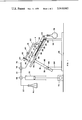
- FIG. 1 is a schematic side view of an assembled elution apparatus
- FIG. 2 is a plan view of an elution head of the apparatus.
- FIG. 3 is a cross-section taken at centrally displaced line Ill-[ll of FIG. 2.
- the elution apparatus comprises an elution head 4 having a base section 6, a sealing skirt 14 about the base section standing proud of its bottom surface 94 (see H6. 3) to seal against a surface of a chromatographic plate 20 cleared of absorption layer 26 around the isolated substance and to thus define an elution chamber 8 (see FIGS. 2 and 3).
- An eluent inlet conduit 10 leads into the elution chamber
- an eluate outlet conduit 12 leads from the elution chamber
- Connection means 28 and 30 are provided for connecting up the inlet and outlet conduits respectively to an eluent supply line 22 and eluate take off line 24.
- Holding means 16 holds the elution head 4 in position on the chromatographic plate 20.
- the bottom surfaces 94 of the base section 6 is flat, and the eluent inlet conduit leads into the elution chamber 8 at a position adjacent the sealing skirt 14 to one side of the elution chamber and the eluate outlet conduit leads from the elution chamber at a position adjacent the sealing skirt to the opposing side of the elution chamber.
- connection means 28 and 30 respectively comprise bores 32 and 34 having threads 36 and 38, communicating with the inlet and outlet conduits l0 and 12 to receive correspondingly threaded hollow screws (not shown) provided at the connection ends of the eluent supply and eluate take off lines (22, 24).
- the holding means 16 for holding the elution head 4 in position on the chromatographic plate 20 comprises a table 52 to support the chromatographic plate and clamp means comprising a lever arm 60 pivotally mounted about pivot via upright 58 fixed to the table 52.
- One free end of the lever arm 60 to one side of the pivot 80 engages with the elution head 4 and the other free end of the lever arm to the other side of the pivot 80 has adjustment means 62 associated with the table 52 com prising an upstanding leg 82 and screw 84 passing through mating threads in the lever arm 62 and seating on the leg 82.
- the clamping action of the lever arm 60 on the elution head 4 can be adjusted by means of the screw.
- the upper section 42 of the elution head 4 is provided with fixing means 40 for fixing one end of the lever arm 60 to the elution head.
- the fixing means comprises a bore 44 into which the end of the lever arm is receivable, and a threaded bore 46 for receiving a grub screw (not shown) for abutting against the section of the lever arm within the bore 44 and to thus fix onto the lever arm.
- the table 52 is carried on a stand 18 and is tiltable between a horizontal position and an inclined position.
- the stand comprises a base plate 48, two pairs of stanchions 50 and 54 and support means 56 comprising a swing arm 92 pivotable about pivot 88.
- the swing arm is provided with extension shoulders 90 at its free end to provide a greater surface against which the underside of the table 52 may be rested when in the inclined position shown in FIG. 1.
- the table 52 is tiltable about pivot 86 at the top end of the pair of stanchionss 50.
- the height of the pair of stanchions 54 above the base plate 48 is chosen so that the table 52 will assume a horizontal disposition when rested on the free ends of the pair of stanchions 54.
- the table 52 may be tilted into the inclined position shown in FlG.
- Reference numerals 68 and 74 refer to three-way cocks, and reference numeral '76 to an eluate outlet line.
- a motor 70 provides the drive to a pump mechanism 72 for pumping eluent along the eluent supply line from eluent supply 64.
- the position of a chromatographically isolated substance on a prepared chromatogram is established, the absorption layer 26 is cut away about the isolated substance, e.g. by means of the serrated end of an open ended tube (not shown), which cuts out a ring in the absorption layer into which the sealing skirt 14 of the elution head 4 is fitted.
- the elution head is then clamped into sealing engagement with the chromatographic plate 20 by means of the clamp means 16.
- This preparation stage is conveniently effected on the table 52, while in its horizontal disposition.
- the table 52 is then tilted upwardly about the pivot 86, the swing arm 92 is lifted into position against the underside of the table, and the eluent supply and eluate take off lines 22 and 24 are connected up to the eluent inlet and eluant outlet conduits respectively.
- An elution apparatus for eluting a chromatographically isolated substance from the absorption layer of a thin layer chromatographic plate, which comprises an elution head having a base section which has a flat bottom surface, a sealing skirt about the base section standing proud of said bottom surface to the extent of only slightly greater than the thickness of the absorption layer to provide a seal between the base section and a surface of the chromatographic plate cleared of absorption layer around the isolated substance and to thus define an elution chamber, an eluent inlet conduit leading into the elution chamber at a position adjacent the sealing skirt to one side of the elution chamber, an eluate outlet conduit leading from the elution chamber at a position adjacent the sealing skirt to the opposing side of the elution chamber, connection means for connecting up the inlet and outlet conduits respectively to an eluent supply line and eluate take off line, a tiltable table to support the thin layer chromatographic plate, and clamp means associated with the table to clamp the elution head
- clamp means comprises a lever arm pivotally mounted to the table, one free end of the lever arm to one side of the pivot being for engagement with the elution head and the other free end of the lever arm to the other side of the pivot having adjustment means associated with the table to adjust the clamping action of the lever arm on the elution head.
- An elution apparatus in which the table is tiltable between a horizontal position and an inclined position substantially parallel to an eluent supply line and eluate take off line leading downwardly via the inlet and outlet conduits to an eluant collection point.
- connection means for connecting up the inlet and outlet conduits respectively to an eluent supply line and eluate take off line comprises threaded bores communicating with the inlet and outlet conduits to receive correspondingly threaded hollow screws provided at the connection ends of the eluent supply and eluate take off lines.
- Method of eluting a chromatographically isolated substance in situ from the absorption layer of a thin layer chromatographic plate which comprises clearing the surface of the chromatographic plate of absorption layer about the isolated substance, confining the absorption layer carrying said isolated substance in situ on the chromatographic plate in a volume which is substantially filled by the volume of the absorption layer carrying the isolated substance, and eluting the isolated substance from the enclosed absorption layer by passing eluent through said confined volume and collecting the eluate.
Landscapes
- Physics & Mathematics (AREA)
- Health & Medical Sciences (AREA)
- Life Sciences & Earth Sciences (AREA)
- Chemical & Material Sciences (AREA)
- Analytical Chemistry (AREA)
- Biochemistry (AREA)
- General Health & Medical Sciences (AREA)
- General Physics & Mathematics (AREA)
- Immunology (AREA)
- Pathology (AREA)
- Treatment Of Liquids With Adsorbents In General (AREA)
Abstract
The invention concerns an elution apparatus and method. The elution apparatus disclosed is suitable for eluting a chromatographically isolated substance directly from the absorption layer of a thin layer chromatographic plate.
Description
United States Patent w;
Falk
[ 1 Nov. 11, 1975 l5 l ELUTION APPARATUS AND METHOD [75] Inventor; Heinz Falk Angst S itzerland [73] Assignee: Sandoz Ltd., Basel. Switzerland [22 Filed: Mar. 7. I974 [21] Appl. No.1 449013 Related US. Application Data [63] Continuation of Ser No 15MB). Mn lll, W 3.
abandoned.
(30] Foreign Application Priorit Data Ma ll lnl $\\|tZerl;md I 1 [52] U.S.Cl...,.. ZlllUl (I :l /WX (Q [ill lnt. CIQ" i v i i .7 a, .7 BOll) l5t'tl8 [58] Field Of Search... lltl/lm 3l (1 55:6?
[Sol References Cited UNITED STATES PATENTS 3.47 .950 llfl twl Clement et alum BID/[Q8 C X Ritlifill 3rl970 Sussman v a v ZlU/IJll C Primal) E,\u!rI1IieJ'J0hn Adee .lzmruey Agent, or Firm-Gerald D Sharkin; Robert S Honor; Walter F. Jewell {57} ABSTRACT The invention concerns an elution apparatus antl method The elution apparatus disclosed is suitable for eluting a chromatographicall isolated substance di rectlt from the absorption layer of a thin la er chromatographic plate.
5 Claims, 3 Drawing Figures U.S. Patent Nov. 11, 1975 Sheet 1 012 3,919,082
US. Patent Nov.1l, 1975 Sheet2of2 3,919,082
FIG.2
ELUTION APPARATUS AND METHOD This is a continuation of application Ser. No. 251,929, filed May 10, 1972, now abandoned.
This invention relates to an elution apparatus and method. More particularly. the invention relates to an apparatus and method which may be employed in thin layer chromatogram evaluation.
Evaluation of the substances in the absorption layer on a chromatographic plate, particularly quantitative evaluation, has in the past essentially involved procedures in which either the area of absorption layer carrying the particular chromatographically isolated substance is scraped off, or the density of the substance in said area is determined. The present invention does not involve either of said procedures, but provides an apparatus and method whereby the chromatographically isolated substance may be eluted directly from the absorption layer.
In accordance with the invention, there is provided an elution apparatus for eluting a chromatographically isolated substance from the absorption layer of a thin layer chromatographic plate, which comprises an elution head having a base section, a seal to seal between the base section and a surface of the chromatographic plate cleared of absorption layer around the isolated substance and to thus define an elution chamber, an eluent inlet conduit leading into the elution chamber, an eluate outlet conduit leading from the elution chamber, connection means for connecting up the inlet and outlet conduits respectively to an eluent supply line and eluate take off line, and holding means for holding the elution head in position on the chromatographic plate.
The base section preferably has a flat bottom surface, and the seal may be provided by a sealing skirt about the base section standing proud of said bottom surface to the extent of only slightly greater than the thickness of the absorption layer from which the isolated substance is to be eluted. An elution head having these features will thus define an elution chamber with the chromatographic plate which will be substantially filled by absorption layer carrying the isolated substance.
80 that flow of eluent will take place through the entire volume of the absorption layer carrying the isolated substance, it is preferable that the eluent inlet conduit leads into the elution chamber at a position adjacent the sealing skirt to one side of the elution chamber and that the eluate outlet conduit leads from the elution chamber at a position adjacent the sealing skirt to the opposing side of the elution chamber.
The connection means for connecting up the inlet and outlet conduits respectively to an eluent supply line and eluate take off line may comprise threaded bores communicating with the inlet and outlet conduits to receive correspondingly threaded hollow screws provided at the connection ends of the eluent supply' and eluate take off lines.
The holding means for holding the elution head in position on the chromatographic plate may comprise a table to support the thin layer chromatographic plate, and clamp means associated with the table to clamp the elution head in position on the chromatographic plate. The clamp means itself may comprise a lever arm pivotally mounted to the table, one free end of the lever arm to one side of the pivot being for engagement with the elution head and the other free end of the lever arm to the other side of the pivot having adjustment means associated with the table to adjust the clamping action of the lever arm on the elution head.
in assembled condition, it is preferable that the eluent inlet conduit open into the elution chamber at a level lower than the opening to the eluate outlet conduit so that eluent flows from the lower level through the absorption layer and out from the elution chamber through the eluate conduit at the higher level. The table is accordingly preferably tiltable between a horizontal position and an inclined position substantially parallel to an eluent supply line and eluate take off line leading downwardly via the inlet and outlet conduits to an eluate collection point.
Further, in accordance with the invention, there is provided a method of eluting a chromatographically isolated substance from the absorption layer of a thin layer chromatographic plate, which comprises sealing off the area of the absorption layer carrying the isolated substance, and eluting in situ the substance from the absorption layer.
The invention will now be described with reference to the accompanying drawings showing, by way of examples only, an elution apparatus in accordance with the invention.
In the drawings:
FIG. 1 is a schematic side view of an assembled elution apparatus;
FIG. 2 is a plan view of an elution head of the apparatus; and
FIG. 3 is a cross-section taken at centrally displaced line Ill-[ll of FIG. 2.
Referring particularly to FIG. 1 of the drawings, the elution apparatus comprises an elution head 4 having a base section 6, a sealing skirt 14 about the base section standing proud of its bottom surface 94 (see H6. 3) to seal against a surface of a chromatographic plate 20 cleared of absorption layer 26 around the isolated substance and to thus define an elution chamber 8 (see FIGS. 2 and 3). An eluent inlet conduit 10 leads into the elution chamber, an eluate outlet conduit 12 leads from the elution chamber Connection means 28 and 30 (see FIGS. 2 and 3) are provided for connecting up the inlet and outlet conduits respectively to an eluent supply line 22 and eluate take off line 24. Holding means 16 holds the elution head 4 in position on the chromatographic plate 20.
As can best be seen from FIG. 3, the bottom surfaces 94 of the base section 6 is flat, and the eluent inlet conduit leads into the elution chamber 8 at a position adjacent the sealing skirt 14 to one side of the elution chamber and the eluate outlet conduit leads from the elution chamber at a position adjacent the sealing skirt to the opposing side of the elution chamber.
Referring now particularly to FIGS. 2 and 3 of the drawings, the connection means 28 and 30 respectively comprise bores 32 and 34 having threads 36 and 38, communicating with the inlet and outlet conduits l0 and 12 to receive correspondingly threaded hollow screws (not shown) provided at the connection ends of the eluent supply and eluate take off lines (22, 24).
Referring again to FIG. 1 of the drawings, the holding means 16 for holding the elution head 4 in position on the chromatographic plate 20 comprises a table 52 to support the chromatographic plate and clamp means comprising a lever arm 60 pivotally mounted about pivot via upright 58 fixed to the table 52. One free end of the lever arm 60 to one side of the pivot 80 engages with the elution head 4 and the other free end of the lever arm to the other side of the pivot 80 has adjustment means 62 associated with the table 52 com prising an upstanding leg 82 and screw 84 passing through mating threads in the lever arm 62 and seating on the leg 82. The clamping action of the lever arm 60 on the elution head 4 can be adjusted by means of the screw. The upper section 42 of the elution head 4 is provided with fixing means 40 for fixing one end of the lever arm 60 to the elution head. The fixing means comprises a bore 44 into which the end of the lever arm is receivable, and a threaded bore 46 for receiving a grub screw (not shown) for abutting against the section of the lever arm within the bore 44 and to thus fix onto the lever arm.
The table 52 is carried on a stand 18 and is tiltable between a horizontal position and an inclined position. The stand comprises a base plate 48, two pairs of stanchions 50 and 54 and support means 56 comprising a swing arm 92 pivotable about pivot 88. The swing arm is provided with extension shoulders 90 at its free end to provide a greater surface against which the underside of the table 52 may be rested when in the inclined position shown in FIG. 1. The table 52 is tiltable about pivot 86 at the top end of the pair of stanchionss 50. The height of the pair of stanchions 54 above the base plate 48 is chosen so that the table 52 will assume a horizontal disposition when rested on the free ends of the pair of stanchions 54. Thus, the table 52 may be tilted into the inclined position shown in FlG. l, which is substantially parallel to eluent supply line 22 and the eluate take off line 24 which leads to an eluate collection point 78. In this position the table is supported by the swing arm 92. in the horizontal position the table is supported by the pair of stanchions 54, in which position the swing arm 92 will have been swung out of the way about the pivot 88.
ln use, the position of a chromatographically isolated substance on a prepared chromatogram is established, the absorption layer 26 is cut away about the isolated substance, e.g. by means of the serrated end of an open ended tube (not shown), which cuts out a ring in the absorption layer into which the sealing skirt 14 of the elution head 4 is fitted. The elution head is then clamped into sealing engagement with the chromatographic plate 20 by means of the clamp means 16. This preparation stage is conveniently effected on the table 52, while in its horizontal disposition. The table 52 is then tilted upwardly about the pivot 86, the swing arm 92 is lifted into position against the underside of the table, and the eluent supply and eluate take off lines 22 and 24 are connected up to the eluent inlet and eluant outlet conduits respectively. The pump 72 is then put in operation, the three- way cocks 68 and 74 are adjusted so that eluent will be pumped along the eluent supply line 22, into the elution chamber 8 through the eluent inlet conduit and, after having passed upwardly through the absorption layer carrying the isolated substance, out through the eluate outlet conduit 12 and along the eluant take off line 24 into collection point It will be appreciated that an apparatus and method in accordance with the invention allows for collection of an isolated substance from a chromatogram, without the danger of losing amounts of the substance following on filtration which otherwise needs to be effected to separate the chromatographically isolated substance from the material of the absorption layer.
What we claim is:
1. An elution apparatus for eluting a chromatographically isolated substance from the absorption layer of a thin layer chromatographic plate, which comprises an elution head having a base section which has a flat bottom surface, a sealing skirt about the base section standing proud of said bottom surface to the extent of only slightly greater than the thickness of the absorption layer to provide a seal between the base section and a surface of the chromatographic plate cleared of absorption layer around the isolated substance and to thus define an elution chamber, an eluent inlet conduit leading into the elution chamber at a position adjacent the sealing skirt to one side of the elution chamber, an eluate outlet conduit leading from the elution chamber at a position adjacent the sealing skirt to the opposing side of the elution chamber, connection means for connecting up the inlet and outlet conduits respectively to an eluent supply line and eluate take off line, a tiltable table to support the thin layer chromatographic plate, and clamp means associated with the table to clamp the elution head in position on the chromatographic plate.
2. An elution apparatus according to claim 1, in which the clamp means comprises a lever arm pivotally mounted to the table, one free end of the lever arm to one side of the pivot being for engagement with the elution head and the other free end of the lever arm to the other side of the pivot having adjustment means associated with the table to adjust the clamping action of the lever arm on the elution head.
3. An elution apparatus according to claim 1, in which the table is tiltable between a horizontal position and an inclined position substantially parallel to an eluent supply line and eluate take off line leading downwardly via the inlet and outlet conduits to an eluant collection point.
4. An elution apparatus according to claim 1, in which the connection means for connecting up the inlet and outlet conduits respectively to an eluent supply line and eluate take off line comprises threaded bores communicating with the inlet and outlet conduits to receive correspondingly threaded hollow screws provided at the connection ends of the eluent supply and eluate take off lines.
5. Method of eluting a chromatographically isolated substance in situ from the absorption layer of a thin layer chromatographic plate, which comprises clearing the surface of the chromatographic plate of absorption layer about the isolated substance, confining the absorption layer carrying said isolated substance in situ on the chromatographic plate in a volume which is substantially filled by the volume of the absorption layer carrying the isolated substance, and eluting the isolated substance from the enclosed absorption layer by passing eluent through said confined volume and collecting the eluate.
Claims (5)
1. AN ELUTION APPARATUS FOR ELUTING A CHROMATOGRAPHICALLY ISOLATED SUBSTANCE FROM THE ABSORPTION LAYER OF A THIN LAYER CHROMATOGRAPHIC PLATE, WHICH COMPRISES AN ELUTION HEAD HAVING A BASE SECTION WHICH HAS A FLAT BOTTOM SURFACE, A SEALING SKIRT ABOUT THE BASE SECTION STANDING PROUD OF SAID BOTTOM SURFACE TO THE EXTENT OF ONLY SLIGHTLY GREATER THAN THE THICKNESS OF THE ABSORPTION LAYER TO PROVIDE A SEAL BETWEEN THE BASE SECTION AND SURFACE OF THE CHROMATOGRAPHIC PLATE CLEARED OF ABSORPTION LAYER AROUND THE ISOLATED SUBSTANCE AND TO THUS DEFINE AN ELUTION CHAMBER, AN ELUENT LEADING INTO THE ELUTION CHAMBER AT A POSITION ADJACENT THE SEALING SKIRT TO ONE SAID OF THE ELUTION CHAMBER, AN ELUATE OUTLET CONDUIT LEADING FROM THE ELUTION CHAMBER AT A POSITION ADJACENT THE SEALING SKIRT TO THE OPPOSING SIDE OF THE ELUTION CHAMBER, CONNECTION MEANS FOR CONNECTING UP THE INLET AND OUTLET CONDUITS RESPECTIVELY TO AN ELUENT SUPPLY LINE AND ELUATE TAKE OFF LINE, A TILTABLE TABLE TO SUPPORT THE THIN LAYER CHROMATOGRPHIC PLATE, AND CLAMP MEANS ASSOCIATED WITH THE TABLE TO CLAMP THE ELUTION HEAD IN POSITION ON THE CHROMATOGRAPHIC PLATE.
2. An elution apparatus according to claim 1, in which the clamp means comprises a lever arm pivotally mounted to the table, one free end of the lever arm to one side of the pivot being for engagement with the elution head and the other free end of the lever arm to the other side of the pivot having adjustment means associated with the table to adjust the clamping action of the lever arm on the elution head.
3. An elution apparatus according to claim 1, in which the table is tiltable between a horizontal position and an inclined position substantially parallel to an eluent supply line and eluate take off line leading downwardly via the inlet and outlet conduits to an eluant collection point.
4. An elution apparatus according to claim 1, in which the connection means for connecting up the inlet and outlet conduits respectively to an eluent supply line and eluate take off line comprises threaded bores communicating with the inlet and outlet conduits to receive correspondingly threaded hollow screws provided at the connection ends of the eluent supply and eluate take off lines.
5. Method of eluting a chromatographically isolated substance in situ from the absorption layer of a thin layer chromatographic plate, which comprises clearing the surface of the chromatographic plate of absorption layer about the isolated substance, confining the absorption layer carrying said isolated substance in situ on the chromatographic plate in a volume which is substantially filled by the volume of the absorption layer carrying the isolated substance, and eluting the isolated substance from the enclosed absorption layer by passing eluent through said confined volume and collecting the eluate.
Priority Applications (1)
| Application Number | Priority Date | Filing Date | Title |
|---|---|---|---|
| US449013A US3919082A (en) | 1971-05-13 | 1974-03-07 | Elution apparatus and method |
Applications Claiming Priority (3)
| Application Number | Priority Date | Filing Date | Title |
|---|---|---|---|
| CH708071A CH538117A (en) | 1971-05-13 | 1971-05-13 | Process for eluting a substance stain from a sorption layer of a thin-layer chromatogram located on a carrier plate and device for carrying out the process |
| US25192972A | 1972-05-10 | 1972-05-10 | |
| US449013A US3919082A (en) | 1971-05-13 | 1974-03-07 | Elution apparatus and method |
Publications (1)
| Publication Number | Publication Date |
|---|---|
| US3919082A true US3919082A (en) | 1975-11-11 |
Family
ID=27175689
Family Applications (1)
| Application Number | Title | Priority Date | Filing Date |
|---|---|---|---|
| US449013A Expired - Lifetime US3919082A (en) | 1971-05-13 | 1974-03-07 | Elution apparatus and method |
Country Status (1)
| Country | Link |
|---|---|
| US (1) | US3919082A (en) |
Cited By (5)
| Publication number | Priority date | Publication date | Assignee | Title |
|---|---|---|---|---|
| US4139458A (en) * | 1977-10-03 | 1979-02-13 | Shuyen Harrison | Preparative centrifugal chromatography device |
| US4261835A (en) * | 1979-04-27 | 1981-04-14 | Creeger Samuel M | Thin layer and paper chromatography cones |
| US4797215A (en) * | 1984-04-05 | 1989-01-10 | Petazon, Inc. | Method for sequential centrifugal stratification chromatography for separating components from mixtures |
| US20030013187A1 (en) * | 2000-02-14 | 2003-01-16 | Rolf Guller | Device for analyzing substances by means of thin layer chromatography |
| US20040164012A1 (en) * | 2003-02-24 | 2004-08-26 | Dunkley John Graham | Chromatography column |
Citations (2)
| Publication number | Priority date | Publication date | Assignee | Title |
|---|---|---|---|---|
| US3477950A (en) * | 1966-11-14 | 1969-11-11 | Eastman Kodak Co | Developing method and apparatus for thin layer chromatography |
| US3503712A (en) * | 1966-05-18 | 1970-03-31 | Research Corp | Apparatus for effecting interactions of fluids at extended solid surfaces |
-
1974
- 1974-03-07 US US449013A patent/US3919082A/en not_active Expired - Lifetime
Patent Citations (2)
| Publication number | Priority date | Publication date | Assignee | Title |
|---|---|---|---|---|
| US3503712A (en) * | 1966-05-18 | 1970-03-31 | Research Corp | Apparatus for effecting interactions of fluids at extended solid surfaces |
| US3477950A (en) * | 1966-11-14 | 1969-11-11 | Eastman Kodak Co | Developing method and apparatus for thin layer chromatography |
Cited By (10)
| Publication number | Priority date | Publication date | Assignee | Title |
|---|---|---|---|---|
| US4139458A (en) * | 1977-10-03 | 1979-02-13 | Shuyen Harrison | Preparative centrifugal chromatography device |
| US4261835A (en) * | 1979-04-27 | 1981-04-14 | Creeger Samuel M | Thin layer and paper chromatography cones |
| US4797215A (en) * | 1984-04-05 | 1989-01-10 | Petazon, Inc. | Method for sequential centrifugal stratification chromatography for separating components from mixtures |
| US20030013187A1 (en) * | 2000-02-14 | 2003-01-16 | Rolf Guller | Device for analyzing substances by means of thin layer chromatography |
| US6709584B2 (en) * | 2000-02-14 | 2004-03-23 | Chemspeed Ltd. | Device for analyzing substances by means of thin layer chromatography |
| US20060054545A1 (en) * | 2002-03-04 | 2006-03-16 | Millipore Corporation | Chromatography columns |
| US20060113232A1 (en) * | 2002-03-04 | 2006-06-01 | Millipore Corporation | Chromatography columns |
| US7534346B2 (en) * | 2002-03-04 | 2009-05-19 | Millipore Corporation | Chromatography columns |
| US20040164012A1 (en) * | 2003-02-24 | 2004-08-26 | Dunkley John Graham | Chromatography column |
| US7041216B2 (en) * | 2003-02-24 | 2006-05-09 | Millipore Corporation | Chromatography column |
Similar Documents
| Publication | Publication Date | Title |
|---|---|---|
| Spackman et al. | Automatic recording apparatus for use in chromatography of amino acids | |
| Stellwagen | [25] Gel filtration | |
| Kilts et al. | Simultaneous quantification of dopamine, 5-hydroxytryptaine and four metabolically related compounds by means of reversed-phase high-performance liquid chromatography with electrochemical detection | |
| US3919082A (en) | Elution apparatus and method | |
| BE903277A (en) | PROCESS FOR CUTTING ABRASIVE FLUID FROM A REINFORCED GLASS SHEET | |
| JP3172660B2 (en) | Equipment for packing chromatography columns | |
| JPS58196455A (en) | Device used for liquid chromatography system and pre-column | |
| Mori et al. | Resistance to spreading of liquids by sharp edged microsteps | |
| Hjertén | Zone electrophoresis in columns of agarose suspensions | |
| Geerdink et al. | Determination of phenoxyacid herbicides in water: Polymeric pre-column preconcentration and tetrabutyl-ammonium ion-pair separation on a PRP-1 column | |
| SE8802126D0 (en) | APPARATUS FOR FLOW FIELD FLOW FRACTIONATION | |
| Sun et al. | The use of polyacrylamide gels for chromatography of proteins | |
| LeBlanc et al. | Capillary zone electrophoresis of fish muscle sarcoplasmic proteins | |
| FR2439043A1 (en) | DEVICE FOR THE SIMULTANEOUS AND CONTINUOUS APPLICATION OF COATING MASSES OF CONSTANT THICKNESS ON BOTH SIDES OF A STRIP MATERIAL | |
| Wyss et al. | Determination of highly protein bound in plasma using high-performance liquid chromatography and column switching, exemplified by the retinoids | |
| Kårsnäs et al. | Two methods for electrophoretic elution of proteins from polyacrylamide gels | |
| Redburn et al. | Stimulus secretion coupling in vitro: A rapid perfusion apparatus for monitoring efflux of transmitter substances from tissue samples | |
| Nishimura et al. | High-performance frontal analysis for the determination of the free drug concentration in protein binding equilibrium using porous polymer stationary phase | |
| CA2157655A1 (en) | Low-pressure chromatography column with automatically movable lid | |
| CN210923291U (en) | A pavement material strength tester | |
| Kekwick et al. | A new type of preparative electrophoresis cell | |
| Keller et al. | Dynamic slurry-packing technique for liquid chromatography columns | |
| CN208018632U (en) | Purified reagent apparatus for placing | |
| Crombeen et al. | High-performance liquid-liquid chromatography | |
| Öfverstedt et al. | Recovery of proteins on a milligram scale from polyacrylamide electrophoresis gels, exemplified by purification of a retinol-binding protein |