US3901034A - Rotary piston engine - Google Patents
Rotary piston engine Download PDFInfo
- Publication number
- US3901034A US3901034A US422593A US42259373A US3901034A US 3901034 A US3901034 A US 3901034A US 422593 A US422593 A US 422593A US 42259373 A US42259373 A US 42259373A US 3901034 A US3901034 A US 3901034A
- Authority
- US
- United States
- Prior art keywords
- rotary piston
- piston engine
- set forth
- transmission
- shaft
- Prior art date
- Legal status (The legal status is an assumption and is not a legal conclusion. Google has not performed a legal analysis and makes no representation as to the accuracy of the status listed.)
- Expired - Lifetime
Links
- 230000005540 biological transmission Effects 0.000 claims abstract description 64
- 238000002485 combustion reaction Methods 0.000 claims description 24
- 230000006835 compression Effects 0.000 claims description 14
- 238000007906 compression Methods 0.000 claims description 14
- 238000001816 cooling Methods 0.000 claims description 14
- 230000001105 regulatory effect Effects 0.000 claims description 3
- 210000002105 tongue Anatomy 0.000 claims description 3
- 230000008859 change Effects 0.000 abstract description 10
- 239000007789 gas Substances 0.000 description 38
- 238000013461 design Methods 0.000 description 8
- 238000006073 displacement reaction Methods 0.000 description 7
- 230000008901 benefit Effects 0.000 description 5
- 238000010276 construction Methods 0.000 description 5
- 239000000446 fuel Substances 0.000 description 5
- 230000004048 modification Effects 0.000 description 5
- 238000012986 modification Methods 0.000 description 5
- 230000002349 favourable effect Effects 0.000 description 4
- 230000007246 mechanism Effects 0.000 description 3
- 238000000034 method Methods 0.000 description 3
- UFHFLCQGNIYNRP-UHFFFAOYSA-N Hydrogen Chemical compound [H][H] UFHFLCQGNIYNRP-UHFFFAOYSA-N 0.000 description 2
- 230000004075 alteration Effects 0.000 description 2
- 239000000463 material Substances 0.000 description 2
- 238000012856 packing Methods 0.000 description 2
- 230000010363 phase shift Effects 0.000 description 2
- 230000008569 process Effects 0.000 description 2
- 238000007789 sealing Methods 0.000 description 2
- 238000004804 winding Methods 0.000 description 2
- IJGRMHOSHXDMSA-UHFFFAOYSA-N Atomic nitrogen Chemical compound N#N IJGRMHOSHXDMSA-UHFFFAOYSA-N 0.000 description 1
- 241000220324 Pyrus Species 0.000 description 1
- 239000004809 Teflon Substances 0.000 description 1
- 229920006362 Teflon® Polymers 0.000 description 1
- 238000010521 absorption reaction Methods 0.000 description 1
- 238000013459 approach Methods 0.000 description 1
- 239000000919 ceramic Substances 0.000 description 1
- 210000000078 claw Anatomy 0.000 description 1
- 150000001875 compounds Chemical class 0.000 description 1
- 230000001276 controlling effect Effects 0.000 description 1
- 239000002826 coolant Substances 0.000 description 1
- 238000012937 correction Methods 0.000 description 1
- 230000003247 decreasing effect Effects 0.000 description 1
- 230000007547 defect Effects 0.000 description 1
- 238000010586 diagram Methods 0.000 description 1
- 229910001873 dinitrogen Inorganic materials 0.000 description 1
- 230000000694 effects Effects 0.000 description 1
- 230000008030 elimination Effects 0.000 description 1
- 238000003379 elimination reaction Methods 0.000 description 1
- 230000005484 gravity Effects 0.000 description 1
- 238000010438 heat treatment Methods 0.000 description 1
- 239000003779 heat-resistant material Substances 0.000 description 1
- 239000001307 helium Substances 0.000 description 1
- 229910052734 helium Inorganic materials 0.000 description 1
- SWQJXJOGLNCZEY-UHFFFAOYSA-N helium atom Chemical compound [He] SWQJXJOGLNCZEY-UHFFFAOYSA-N 0.000 description 1
- 230000006872 improvement Effects 0.000 description 1
- 230000000266 injurious effect Effects 0.000 description 1
- 238000009434 installation Methods 0.000 description 1
- 239000007788 liquid Substances 0.000 description 1
- 238000013021 overheating Methods 0.000 description 1
- 235000021017 pears Nutrition 0.000 description 1
- 230000001172 regenerating effect Effects 0.000 description 1
- 230000000717 retained effect Effects 0.000 description 1
- 230000008646 thermal stress Effects 0.000 description 1
- XLYOFNOQVPJJNP-UHFFFAOYSA-N water Substances O XLYOFNOQVPJJNP-UHFFFAOYSA-N 0.000 description 1
Images


Classifications
-
- F—MECHANICAL ENGINEERING; LIGHTING; HEATING; WEAPONS; BLASTING
- F02—COMBUSTION ENGINES; HOT-GAS OR COMBUSTION-PRODUCT ENGINE PLANTS
- F02G—HOT GAS OR COMBUSTION-PRODUCT POSITIVE-DISPLACEMENT ENGINE PLANTS; USE OF WASTE HEAT OF COMBUSTION ENGINES; NOT OTHERWISE PROVIDED FOR
- F02G1/00—Hot gas positive-displacement engine plants
- F02G1/04—Hot gas positive-displacement engine plants of closed-cycle type
- F02G1/043—Hot gas positive-displacement engine plants of closed-cycle type the engine being operated by expansion and contraction of a mass of working gas which is heated and cooled in one of a plurality of constantly communicating expansible chambers, e.g. Stirling cycle type engines
- F02G1/045—Controlling
-
- F—MECHANICAL ENGINEERING; LIGHTING; HEATING; WEAPONS; BLASTING
- F01—MACHINES OR ENGINES IN GENERAL; ENGINE PLANTS IN GENERAL; STEAM ENGINES
- F01C—ROTARY-PISTON OR OSCILLATING-PISTON MACHINES OR ENGINES
- F01C1/00—Rotary-piston machines or engines
- F01C1/02—Rotary-piston machines or engines of arcuate-engagement type, i.e. with circular translatory movement of co-operating members, each member having the same number of teeth or tooth-equivalents
- F01C1/063—Rotary-piston machines or engines of arcuate-engagement type, i.e. with circular translatory movement of co-operating members, each member having the same number of teeth or tooth-equivalents with coaxially-mounted members having continuously-changing circumferential spacing between them
- F01C1/07—Rotary-piston machines or engines of arcuate-engagement type, i.e. with circular translatory movement of co-operating members, each member having the same number of teeth or tooth-equivalents with coaxially-mounted members having continuously-changing circumferential spacing between them having crankshaft-and-connecting-rod type drive
-
- F—MECHANICAL ENGINEERING; LIGHTING; HEATING; WEAPONS; BLASTING
- F01—MACHINES OR ENGINES IN GENERAL; ENGINE PLANTS IN GENERAL; STEAM ENGINES
- F01C—ROTARY-PISTON OR OSCILLATING-PISTON MACHINES OR ENGINES
- F01C20/00—Control of, monitoring of, or safety arrangements for, machines or engines
- F01C20/18—Control of, monitoring of, or safety arrangements for, machines or engines characterised by varying the volume of the working chamber
-
- F—MECHANICAL ENGINEERING; LIGHTING; HEATING; WEAPONS; BLASTING
- F02—COMBUSTION ENGINES; HOT-GAS OR COMBUSTION-PRODUCT ENGINE PLANTS
- F02G—HOT GAS OR COMBUSTION-PRODUCT POSITIVE-DISPLACEMENT ENGINE PLANTS; USE OF WASTE HEAT OF COMBUSTION ENGINES; NOT OTHERWISE PROVIDED FOR
- F02G1/00—Hot gas positive-displacement engine plants
- F02G1/04—Hot gas positive-displacement engine plants of closed-cycle type
- F02G1/043—Hot gas positive-displacement engine plants of closed-cycle type the engine being operated by expansion and contraction of a mass of working gas which is heated and cooled in one of a plurality of constantly communicating expansible chambers, e.g. Stirling cycle type engines
-
- F—MECHANICAL ENGINEERING; LIGHTING; HEATING; WEAPONS; BLASTING
- F02—COMBUSTION ENGINES; HOT-GAS OR COMBUSTION-PRODUCT ENGINE PLANTS
- F02G—HOT GAS OR COMBUSTION-PRODUCT POSITIVE-DISPLACEMENT ENGINE PLANTS; USE OF WASTE HEAT OF COMBUSTION ENGINES; NOT OTHERWISE PROVIDED FOR
- F02G2258/00—Materials used
- F02G2258/10—Materials used ceramic
-
- F—MECHANICAL ENGINEERING; LIGHTING; HEATING; WEAPONS; BLASTING
- F02—COMBUSTION ENGINES; HOT-GAS OR COMBUSTION-PRODUCT ENGINE PLANTS
- F02G—HOT GAS OR COMBUSTION-PRODUCT POSITIVE-DISPLACEMENT ENGINE PLANTS; USE OF WASTE HEAT OF COMBUSTION ENGINES; NOT OTHERWISE PROVIDED FOR
- F02G2270/00—Constructional features
- F02G2270/02—Pistons for reciprocating and rotating
Definitions
- a rotary piston engine h a plurality of Sets of annw lwhubumhmcd' lar members forming cylinders and annular segment pistons moving inside the cylinders and provided with [30] Formgn Appl'catmn Prmmy Dam a hollow shaft and a core shaft extending coaxially All ⁇ ; Q 1970 Gcrmimy 3041389 therethrough and with a common shaft A transmis sion is provided for connecting the central and core 60/519; 60/395]; 123/347; shafts to the common shaft whose axis is eccentric to 418/!8; l23/8.4l; 418/33 the other two shafts.
- a central ring arrangement is l l l Cl F03g 7/06; 2 U04; FOIC 1/0U provided which is connected by links to double-crank Field Search 60/519 39-63; connectors mounted on the central and core shafts by 123/847; 418/1 links.
- the positions of the links may be varied to change the phase between the pistons and cylinders of i 1 References Cited the sets.
- the piston operates on the Stirling principle.
- the invention relates to rotary piston members of the type having annular members forming cylinders and annular segment pistons moving inside the cylinders.
- the said patent relates to a rotary piston engine and more particularly to a rotary piston engine having annular members forming cylinders and annular segment pistons moving on the insides of said cylinders, the said segment pistons having disc type hubs bearing against one another and constituting with their circumferential surfaces the inner walls of the corresponding cylinders, wherein the first of said hubs is connected with a central hollow shaft and the second of the hubs is connected with a core shaft extending coaxially through the said hollow shaft, said two shafts working on a common shaft, and wherein the said engine has at least two cylinders with segment pistons cooperating therewithin and lying one behind the other in the direction of the central axis of said shaft.
- the aim of the former patent is to provide an engine of the type here in question which has a compact shape and delivers high output at low weight, can be manufactured and assembled at low cost and has low wear, wherein heat expansion in service causes no disturbances due to gripping, simple seals are usable with low seal wear, and wherein, fur ther, a cylinder charge may be effected by simple means, allowing precise control of charge filling.
- An advantageous embodiment was recommended for this purpose, permitting in particular the rotary piston engine to be employed as a steam engine, whereby it can be assembled in the manner of a modular system and can be expanded as desired.
- hollow shafts and core shafts extend on both sides of the transmission and that at least one annular cylinder with annular segments is located on each side of the transmission, wherein in the case of a clockwise hot gas circulation process, for example, the group on one side serves to compress a cooled gas, while the group on the other side serves to displace and expand the additionally heated gas supplied to it.
- lines to a cooling heat exchanger which is connected with the intake side of the compression group, can be provided for the gas which is to be expanded.
- the transmission is designed in such a manner as to enable it to control the movements of the annular segment pistons of the groups on each side independently of the other group, and in such a manner that the pivot points of the connecting rods on the ring of the transmission are adjustable relative to one another, preferably through hydraulic or mechanical means.
- this is referred to as the phase angle (1).
- This phase angle employed for controlling the engine, plays a decisive role in the design of the engine. Shifting the phase permits the entire output range to be passed through. It is not necessary to alter the pressure of the working medium. In the current state of the art, the above effect cannot be realized in a conventional reciprocating hot gas engine.
- phase shifting of the warm and cold sections relative to one another is provided in a simple manner. If the ring is designed in a divided, clampable and rotatable manner, the angle between the pairs of pins can also be shifted. In a special case, it is a compound two-way hydraulically clamped rotating ring.
- phase shifting is offered by means of mechanical differential gearing, built into the transmission in such a manner that there is one flywheel mass each in the form of bevel crown gears between the two four-rod linkage on the warm and cold sides instead of the eccentrically mounted transmission rotating ring, wherein the spur bevel gear giving off the energy is toothed on the circumference of its flywheel mass rim, leading to the power take-off by means of a pinion.
- One or two bevel pinions are swivel mounted between the two spur bevel gears by means of a pinion cage so that the rotation of the driving spur bevel gear is transmitted to the driven spur bevel gear, which rotates in the opposite direction, in every swivel position.
- the swivel planet bridge which carries a worm gear segment, is mounted on a concentric hub, projecting from a wall which divides the engine housing into two cylindrical parts.
- a bolt on whose two projecting ends the above spur bevel gears rotate by means of antifriction bearings, extends through the hub hole.
- the spur bevel gears serve as a flywheel mass, having two pivot pins each on the side opposite the teeth, with which the two four-rod linkages engage.
- the spur bevel gears are mounted relative to one another in such a manner that the pair of pins on one side rotates a certain constant angle ahead of the pair of pins on the other side.
- the pinion cage can be swivelled to both sides by means of a toothed rim and self-locking worm, an additional rotary movement is given to the spur bevel gears by means of the bevel pinions with shifting by means of the worm, causing the pairs of pins to also be either rotated away from or closer to one another.
- the cold" and warm segment pistons must rotate in opposite directions. However this can be accomplished through suitable placement of the inlet and outlet openings in the cylinder.
- a double-toothed spur bevel gear which also rotates in the opposite direction, is employed instead of the spur bevel gear on the cold side.
- the teeth on the rear act on an additional pinion, which is mounted in a second wall. The said additional pinion now rotates the cold spur bevel gear in the same direction as the warm one.
- the transmission (follower rod) comprises a ring (termed rotating ring in a special case) mounted eccentrically in relation to the axis of the annular cylinder, on which the hollow shafts and core shafts are pivoted through several cranks (starting rod) by means of connecting rods (link rods).
- the ring can be mounted in a holder, which can be swivelled around a laterally rigid shaft. This permits the holder to be designed as a hollow cylinder and to hold the ring.
- the holder can bear against an eccentric shaft or hydraulic cylinder which can be shifted manually or by means of a motor.
- control of the output can be accomplished in such a manner that, by shifting the eccentricity, the working volumes of the annular cylinders on both sides of the transmission are increased or decreased.
- the holder can also be in the shape of an axle, guided in slotted pieces and mounted concentrically to the rotating ring.
- the engine operates with external combustion in the closed circulation through displacing members, regenerators, and compressors, wherein burners, heaters and coolers maintain the thermic cycle of the medium. Characteristic is its rotary piston design according to the modular principle.
- annular cylinder with annular segment pistons acting as a compressor for the combustion air and/or cooling air, can be located on one side, preferably on the compression side, to provide combustion air for the combustion chamber and secondary air for reg ulating the combustion and the heat. It is practical for the heat exchanger located in front of the burner to pre-heat this combustion air through the exhaust.
- the heat exchanger and the associated air paths and/or the combustion chamber are located concentrically to the annular cylinder or cylinders. It is also favorable if the heat exchanger admitting the coolant, preferably water, concentrically surrounds the annular cylinder or cylinders acting as compressors.
- This invention therefore describes an engine which appears particularly suitable as an automotive engine. It possesses the known advantages of the Stirling engine such as quiet, low-wear, vibration-free, silent operation, since through the external constant-pressure corribustion the combustion surges of internal combustion or diesel engines cannot result.
- the combustion is simple to control and complete combustion is ensured, without the injurious exhaust whose elimination requires so much effort. This all has a favorable effect on total efficiency, which is at least as high as that of a die sel engine.
- the engine's multi-fuel capability without cold-starting difficulties is also advantageously divided into a warm side and a cold side, whereby the transmission housing in the center serves for installation of the engine as well as absorption of thermal stresses and rod forces.
- this engine also achieves a simpler shape with more versatile design, a more favorable center of gravity, a higher power-to-weight ratio, lower structural volume and a simpler, easier to control method of regulation as well as the resulting lower first costs with increased performance.
- the above invention therefore describes an engine which does not have the above mentioned defects of a conventional hot gas engine and therefore ap pears particularly well suited as an automotive engine.
- a thermal engine operates with a closed, regenerative thermodynamic cycle under compression and expansion of the working medium at different temperatures, so that the basic principle is to convert heat to work.
- the working medium such as nitrogen gas or hydrogen gas
- the working medium is compressed in the space between the compressor cylinder ring disc and the displacement ring disc by a driving engine and then flows through the water-cooled heat exchanger (cooler), the regenerator and the freezer (heat exchanger ll), into the space between the cylinder head and the top of the displacement member.
- the working medium expands there.
- the temperature drops, causing heat to be withdrawn from the vicinity of the cylinder head and the freezer.
- the result is liquid air at a temperature of between -80 and 80C.
- the hot air engine and the gas refrigerating machine thus differ only in the temperature gradients of the expansion cylinder.
- a positive temperature difference relative to the ambient temperature through suitable means is desired.
- the refrigerating machine this is mainly accomplished in that the compression and expansion cylinder are driven by a driving engine, that is, by an electric motor, whereby the employed fourrod linkage rotates in such a manner that the change in volume of the expansion area precedes the change in volume of the compression area. In this manner, phase shifting can easily be brought about during operation through suitable known measures.
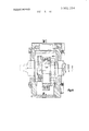
- FIG. I is a longitudinal vertical section through a rotary piston engine according to this invention.
- FIG. 2 is a vertical section taken along the line II-Il of FIG. 1,
- FIGS. 2a and 2b are perspective views of two of the cylinders
- FIG. 3 is a cross-section of a detail of an arrangement according to FIG. 1,
- FIG. 4 is a longitudinal vertical section through a modified embodiment of the invention
- FIG. 5 is a cross-section of a detail of an arrangement according to FIG. 4,
- FIG. 6 is a vertical section of a part of a further modified embodiment of this invention.
- FIG. 7 is a front view of an arrangement according to FIG. 6,
- FIG. 8 is a view corresponding to FIG. 6 of a modification of an arrangement according to FIGS. 6 and 7,
- FIGS. 9a 9f are a series of views showing the volumes of two working cylinders in the first embodiment during one revolution
- FIG. 10 is a diagrammatic view of the cylinder volumes throughout a revolution of 360
- FIGS. 11a llfare a series of views showing the volumes of two working cylinders in the second embodiment illustrated in the same manner and,
- FIG. 12 is an illustration of the embodiment corresponding to FIG. 10.
- FIGS. 1 to 3 The embodiment of a rotary piston engine serving as a hot gas engine serving illustrated in FIGS. 1 to 3 comprises five annular cylinders l to 5, arranged behind one another coaxially on shaft 6.
- Cylinders 2, 3 and 4 are formed of rings, wherein intermediate rings 11 are located coaxially between them.
- External cylinders 1 and 5 are designed as end members and close the ends of annular segment pistons 7 and 9 axially to the outside, while also supporting core shafts l2 and 13.
- Hubs of annular segment pistons 8 are connected with these core shafts l2 and 13 by means of a spline connection, for example, while the annular segment pistons 7 form a hollow shaft with their hubs 10 which are positively connected with one another by being inserted into one another in the circumferential direction.
- the rotary piston engine illustrated in FIG. 1 is designed as a hot gas engine with the left half, viewed from the transmission housing 14 in the drawing, operating as a compressor while the right half is provided as a displacement member for expanding a gas.
- a gas that is air, hydrogen gas or helium, is supplied by pressure to the cylinders 2 and 3 through a heat exchanger 35.
- the gas is supplied to cylinders 4 and 5 from cylinders 2 and 3, acting as compressors, through the coils of a heat exchanger 36.
- the heat exchanger 36 is surrounded by heated air, which is heated in a combustion chamber 37.
- Said combustion chamber 37 is provided with a fuel nozzle in which the fuel is burned with primary air.
- secondary air is supplied to the hot flow of gas in the subsequent location 39 and burned again. Said secondary air is heated beforehand in the heat exchanger 40 termed a pre-heater.
- the hot exhaust which permits complete combustion of the fuel, then flows past heat exchanger 36 and through heat exchanger 40 into the exhaust pipe.
- the working gas heated in the heat exchanger 36 and supplied to cylinders 4 and 5, can expand in these cylinders while giving ofi work, that is, the gas is supplied to cylinders 2 and 3 through the cooling heat exchanger 35 by displacement members 7 and 8.
- regenerators 41 Provided between the two heat exchangers 35 and 36 are regenerators 41, which prevent excessive losses by storing and giving off heat.
- the gas flows through these re generators both after leaving cylinders 2 and 3 before entering heat exchanger 36 and after leaving cylinders 4 and 5 before entering heat exchanger 35.
- Cylinder 1 also serves as a compressor. It sucks in air and supplies said air through to an annular system 410, from which the air flows out through openings in the wall of the annular chamber into space 51.
- the combustion chamber is shown in more detail in FIG. 3.
- 50 is the fuel nozzle.
- the fresh air for the combustion chamber flows out of the ring 41a, through the space 51 and into the dome 52. Another portion of the fresh air flows into tubes 53 of the pre-heater 40, egresses at the other end, reverses its direction of flow in space 53a and enters the rotating flames in the combustion chamber as preheated secondary air through a toroidal-shaped burner having holes 53b and slots. After passing the heat exchanger 36, the gases pass through the spaces of heat exchange 40 and exhaust at 53c.
- the cooler layers of air provide effective protection against burning out and local overheating of the toroidal burner and the hoodshaped finned cylinder body 51, termed the cylinder head.
- Said cylinder head 51 of a high-quality heatresistant material, is comprised primarily of a basic body 50, designed hump-shaped for rigidity, which also carries the connecting rods 5b of the in-line cylinders. Cast on the surface facing the rotating flames are spirally twisted fins of a material having good thermal transmission properties.
- the internal lining which gives annular cylinder 5 its cylindrical shape, can also be of a material of this type. Because of this arrangement, cylinder 5 gains its operating heat faster when starting than cylinder 4, for example.
- FIGS. 2a and 2b show perspective views of the cylinders 4 and 5, respectively, the pistons 7 and 8 turn within the cylinders 11.
- One of the pistons for example the piston 8, has connected with it a ring 8 which extends around the interior of the cylinder 11 and is provided with openings 8a and 8b, respectively which open into ring channels 11a and 1 lb, respectively which extend around the periphery of the ring 8'.
- the channels 110 and 11b are connected by pipes to coils 101, 102 and 103, 104, respectively, each of which coils makes several turns side-by-side along the outside of the hot portion of the machine.
- the ring channels 110 and 11d are connected with coils 105, 106 and 107, 108, respectively, these being the inner coils of the heat exchanger 36 shown in FIG.
- the pipes 101 and 102 are connected to one pair of the regenerators, pipes 103 and 104 to another pair, pipes 105 and 106 to another pair and pipes 107 and 108 to another pair. It may be desirable in practice to have four pairs of regenerators but this is not essential to the invention in its broader aspects.
- the construction of the cylinders 2 and 3 is similar, that is, they have annular channels similar to those of FIGS. and 2b.
- the channels of cylinder 2 are connected through pipes 109 to the cooler 35, through which the gases pass to the regenerators.
- Cooler 35 is divided into four partly annular segments, each connected to one pair of the regenerators. There are two pairs of outlets for each cylinder, and the pairs of outlets are connected each to a different segment of the cooler 35 and thus to clifi'erent pairs of regenerators.
- the gases from one of the cylinders 2 or 3 pass through one of the pairs of regenerators 41 into one of the cylinders 4 or 5, while at the same time heated gases from the other of the cylinders 4 or 5 are passing through a different pair of regenerators to the other of the cylinders 2 or 3.
- the expanded gas goes then over the pipe connections to the regenerator, which consists of a wave shaped ceramic mass, which absorbs a great part of the heat, so that the outlet temperature of the medium is essentially lower than at the introduction of the medium and for the next cycle the cooled gases are available.
- the drive mechanism in the quadrant 15 is explained in connection with FIGS. 6, 7 and 8. This is a mechanically operating phase shifting.
- regenerators 41 The gases move alternately through the regenerators 41 first from the cool to the warm side and then from the warm to the cool side. At each working cycle the hot gas moves towards the right and on the other hand the cooled gas towards the left.
- regenerators are provided in the middle part of the arrangement which are spaced around a circle and through which the medium flows. Each regenerator serves for receiving cool medium flowing from left to right and then the hot medium from right to left, and has the purpose of taking out heat from the warm medium and giving it back the cold medium.
- the control of the gas through the regenerator is accomplished by the pistons and the openings provided and valves are unnecessary.
- Annular cylinders 1, 2 and 3 are arranged on one side of a transmission mechanism 14 and annular cylinders 4 and 5 on the other.
- Said transmission mechanism ensures that, during a rotary movement, annular segment pistons 7 and 8, which have almost the same crosssection as annular cylinders l to 5, are retarded or accelerated in relation to one another so that the space between them is altered in a specified manner and always attains a maximum and a minimum value.
- the transmission 14 is designed in such a manner that it controls the movement of the core shafts 12 and 13 located on both sides of it as well as the movement of the hollow shaft formed by the hubs 10 of the annular segment pistons 7.
- the transmission 14 (FIG. 2) comprises a ring 16 rotating around shaft 15 eccentrically to shaft 6 and provided with four pins 17, 18, 19 and 20, with which, by means of connecting rod tongues 25, the hollow shafts formed by the hubs l0 and the annular segment pistons 7 are connected with the aid of cranks 21 and 22, with the core shafts 12 and 13 which are positively connected with one another with the aid of cranks 23 and 24, crank 21 being connected with pin 18, crank 22 with pin 20, crank 23 with pin 19 and crank 24 with pin 17, each by means of a connecting rod (pitman) 25.
- annular segment pistons 7 and 8 This arrangement permits annular segment pistons 7 and 8 to have unequal speeds of rotation during one revolution, causing the distance between them, which is employed as the working space, to change.
- the maximum and minimum size of these working spaces is determined by the eccentricity between shafts 6 and shaft 15 of ring 16 (follower rod).
- Ring 16 is seated in a holder 26, designed as a hollow cylinder and arranged so that it can swivel around a lateral shaft 27.
- Holder 26 is supported against the housing 30 surrounding the transmission 14, designated transmission housing, by means of a rod 28a with an interposed spring 29 a hydraulic arrangement can also be provided instead.
- a hydraulic arrangement can also be provided instead.
- an eccentric 31 which, in the embodiment example according to FIG. 2, can be rotated by means of a servo motor and the subsequent rotation of the eccentric shaft 31.
- Holder 26 can thus be swivelled around its shaft 27, so that the shaft 15 of ring 16 makes a swivel movement, thus altering the eccentricity with respect to shaft 6.
- the holder can also be swivelled hydraulically or by means of a worm segment or spindle nut.
- crank pins l7, 18, 19 and 20 in ring 16 can be retained by means of pistons or similar members located in the ring under oil pressure, by means of which the distance between them can be adjusted through hydraulic means in a manner not described in more detail. In particular adjustment of the pair of crank pins 18 and 19 relative to crank pins 17 and 20 is intended.
- a flywheel 42 provides uniform drive speed to core shaft 12
- the drive in the modification according to FIG. 4 (top half) and FIG. 5 is lateral from the center of the transmission housing.
- the ring 43 (rotating ring) rotates at a constant speed, its toothed rim 43a acting upon a driving pinion 44, mounted laterally in the transmission housing 14.
- the pinion 44 which has a special tooth correction from to across the width of its teeth, adjusts to the new position of the teeth of the toothed rim under spring pressure or cam disc guidance, thus remaining engaged during the swivel movement.
- the power take-off is from the center of the transmission housing, which is also provided with clamping claws, whereby it should hardly be necessary to interpose elastic sets of springs. Otherwise, the embodiment according to FIG. 5 corresponds to that according to FIG. 2.
- FIG. 12 An advantage of an arrangement of this type is that harmonic curves according to FIG. 12 are produced with a constant speed of the eccentrically mounted ring where the relationship cylinder volume change to angular frequency" can be seen in the diagram.
- FIGS. 1 and 2 in which one of the piston shafts rotates at a constant speed, only sinusoidal cylinder volume change curves according to FIG. result.
- FIGS. lla 11f show, in a similar manner to FIGS. 9a 9f, the course, in the second modification, of the effective working volumes between two annular segment pistons rotating on different sides of the transmission housing.
- This second modification in which the drive is from the center of the longitudinal axis, provides the advantage of saving at least one sealing side on the cool compression side as well as harmonic rod and accelerative forces. This also lends itself to stepping up the drive since, as is known, a hot gas engine only provides optimum performance at low speed ranges. In addition, it is also possible for the take-off to be inclined and at the side for marine engines, for example.
- a certain eccentricity between shafts 6 and 15 and a certain distance between crank pins 17 20 (phase angle) among one another provides the course of the effective working volumes between two annular segment pistons 7 and 8, located on different sides of the transmission 14, illustrated in FIGS. 9a 9f and FIG. 10.
- FIGS. 9a 9f and FIG. 10 For reasons of simplicity, only the volume existing between one of the neighboring ends of two annular segment pistons 7 and 8 is illustrated, while in reality both ends of annular segment pistons 7 and 8 include efi'ective working volumes.
- FIGS. 9a 9f for example, the change in volume within cylinders 3 and 4 is illustrated, wherein said cylinders are located on different sides of the transmission housing.
- the volume designated 33 belongs to cylinder 3, while the volume designated 34 belongs to cylinder 4.
- the change in volume 34, belonging to cylinder 4 precedes that of volume 33 of cylinder 3.
- FIG. 10 in which the change in cylinder volume is illustrated throughout a revolution of an annular segment piston broken down in the form of angles (cylinder volume to angular revolution, lever A-A'). It can be seen that the maximum and minimum sine-shaped volume changes of volumes 33 and 34 are staggered by approximately 90, which approximates prior art hot gas engines.
- Volume 34 for example, approaches a maximum at 230, while this is not achieved by volume 33 until approximately 320. The minimums are naturally also staggered in the same manner.
- the amplitude of sine-shaped curves 33 and 34 can be set by the transmission 14, while the distance between crank pins 18 and 19 and crank pins 17 and 19 determines to what extent curves 33 and 34 are displaced in phase relative to one another.
- FIGS. 6 and 7 describe a mechanical solution of phase shifting between the warm and cold cylinder sections of the engine.
- Shaft 61 on the left side of the transmission relates to the cold side of the engine, shaft 62 to the warm side.
- One flywheel mass 64 or 65 each for the warm and cold sides rotates on shaft 63 as a part of the transmission.
- Flywheel mass 64 which rotates on a rigid shaft 64, initiates the torque and transmits said torque to pinion shaft 68 through a toothed rim 67, said pinion shaft leading to the drive.
- Flywheel mass 65 serves to compensate for the cold rotational and linkage forces.
- Both flyweel masses have bevel gear teeth and one pair of pins 640 and 65a on the back of each pivot for the corresponding linkages 67 and 68, staggered relative to one another by the phase angle dz.
- one or two planet gears 70 are mounted in a swivel planet bridge 69, said planet bridge being swivelly mounted around shaft 63, wherein the spur bevel gear 65 is caused to rotate in the opposite direction.
- the bridge On its circumference, the bridge possesses a worm gear segment 71 in which a self-locking worm gear 72 can engage.
- the bridge 69 and the gear 70 mounted thereon swivels in the sense of rotation of the spur bevel gear 64 or in the opposite direction.
- the cold section rotates in the opposite direction from the warm segment. This can be taken into consideration through appropriate relocation of the inlet and outlet openings on both sides of the engine.
- spur bevel gear 85 with double toothing is divided and made hydraulically clampable in a similar manner to the rotating ring in FIG. I, the bridge 81 with worm gear and worm can be eliminated.
- a rotary piston engine having a plurality of sets of annular members forming cylinders and annular segment pistons moving on the insides of said cylinders, the said segment pistons having first and second disc type hubs bearing against one another and constituting with their circumferential surfaces the inner walls of the corresponding cylinders, a central hollow shaft and a core shaft extending coaxially through the said central hollow shaft, the first of said hubs being connected with said central hollow shaft and the second of said hubs being connected with said core shaft, a common shaft, a transmission connecting said central hollow and core shafts to said common shaft, said common shaft being eccentrically mounted with respect to said axis of the central hollow and core shafts, the said engine having sets of annular cylinders with segment pistons cooperating therewithin, there being at least one set on each side of the transmission, the sets on one side of the transmission forming an expansion part while the set on the other side of the transmission forms a compression part, a cooler, at regenerator and a heater, means connecting said cooler, said regenerator and said heater
- phase shifting means comprising mechanical differential gearing, installed in the transmission to provide one flywheel mass for each set in the form of bevel gears.
Landscapes
- Engineering & Computer Science (AREA)
- Mechanical Engineering (AREA)
- General Engineering & Computer Science (AREA)
- Chemical & Material Sciences (AREA)
- Combustion & Propulsion (AREA)
- Transmission Devices (AREA)
Abstract
A rotary piston engine with a plurality of sets of annular members forming cylinders and annular segment pistons moving inside the cylinders and provided with a hollow shaft and a core shaft extending coaxially therethrough and with a common shaft. A transmission is provided for connecting the central and core shafts to the common shaft whose axis is eccentric to the other two shafts. A central ring arrangement is provided which is connected by links to double-crank connectors mounted on the central and core shafts by links. The positions of the links may be varied to change the phase between the pistons and cylinders of the sets. The piston operates on the Stirling principle.
Description
United States Patent I 1 I11] 3,901,034 Munzinger Aug. 26, 1975 I ROTARY PISTON ENGINE 1460.344 8/1969 Johnson 60/519 3.685.928 8/1972 Munzingcr 418/18 [76] Inventor: Friedrich Munzlnger, 46
Hohenrandstrassc. 7000 Stuttgart Germmy Primary Exuminer-Clarence R. Gordon (22] Filed: Dec. 6, I973 [21] Appl. No.: 422,593
57 AB TRA T Related US. Application Data I 1 S C [(13] Continuation-impart of Scr. Nor |73.l)73 Aug. I9. A rotary piston engine h a plurality of Sets of annw lwhubumhmcd' lar members forming cylinders and annular segment pistons moving inside the cylinders and provided with [30] Formgn Appl'catmn Prmmy Dam a hollow shaft and a core shaft extending coaxially All}; Q 1970 Gcrmimy 3041389 therethrough and with a common shaft A transmis sion is provided for connecting the central and core 60/519; 60/395]; 123/347; shafts to the common shaft whose axis is eccentric to 418/!8; l23/8.4l; 418/33 the other two shafts. A central ring arrangement is l l l Cl F03g 7/06; 2 U04; FOIC 1/0U provided which is connected by links to double-crank Field Search 60/519 39-63; connectors mounted on the central and core shafts by 123/847; 418/1 links. The positions of the links may be varied to change the phase between the pistons and cylinders of i 1 References Cited the sets. The piston operates on the Stirling principle.
UNITED STATES PATENTS 3.275.222 9/1966 Mcycr .r 60/396! 25 Claims, 24 Drawing Figures PATENTED AUG 2 81975 DEE SHEET b i: 5 NS 5 t PATENTED M182 8 I975 SHEET PATENTEDAUGZBIQYS 3.901.034 SHEET 8 1O fedion m'm Fly. 5
ROTARY PISTON ENGINE RELATED APPLICATIONS This application is a continuation-in-part of application Ser. No. 173,073, filed Aug. 19, 1971, now abandoned.
BACKGROUND OF THE INVENTION 1. Field of the Invention The invention relates to rotary piston members of the type having annular members forming cylinders and annular segment pistons moving inside the cylinders.
The present application relates to an improvement of the rotary piston engine, specified in the co-pending U.S. patent by the same inventor, U.S. Pat. No. 3,685,928, of Aug. 22, 1972.
The said patent relates to a rotary piston engine and more particularly to a rotary piston engine having annular members forming cylinders and annular segment pistons moving on the insides of said cylinders, the said segment pistons having disc type hubs bearing against one another and constituting with their circumferential surfaces the inner walls of the corresponding cylinders, wherein the first of said hubs is connected with a central hollow shaft and the second of the hubs is connected with a core shaft extending coaxially through the said hollow shaft, said two shafts working on a common shaft, and wherein the said engine has at least two cylinders with segment pistons cooperating therewithin and lying one behind the other in the direction of the central axis of said shaft. The aim of the former patent is to provide an engine of the type here in question which has a compact shape and delivers high output at low weight, can be manufactured and assembled at low cost and has low wear, wherein heat expansion in service causes no disturbances due to gripping, simple seals are usable with low seal wear, and wherein, fur ther, a cylinder charge may be effected by simple means, allowing precise control of charge filling. An advantageous embodiment was recommended for this purpose, permitting in particular the rotary piston engine to be employed as a steam engine, whereby it can be assembled in the manner of a modular system and can be expanded as desired.
SUMMARY OF THE INVENTION It is one object of this invention to further develop the rotary piston engine of the type here in question on the basis of the underlying idea of the basic patent, creating an engine which is not only of simple design and capable of being assembled according to the modular system, but which is also suitable as an engine for clockwise and counter-clockwise gas and steam circulation processes, for example as a hot gas engine, operating on the principle of the Stirling engine. What is new and unique is that hollow shafts and core shafts extend on both sides of the transmission and that at least one annular cylinder with annular segments is located on each side of the transmission, wherein in the case of a clockwise hot gas circulation process, for example, the group on one side serves to compress a cooled gas, while the group on the other side serves to displace and expand the additionally heated gas supplied to it. To achieve closed circulation of the gas in this hot gas engine with external combustion, lines to a cooling heat exchanger, which is connected with the intake side of the compression group, can be provided for the gas which is to be expanded. To avoid excessive thermal losses in this embodiment, it is practical for the gas to be led from one group to the other, in both directions, through a regenerator, which is always located in front of a heat exchanger. To enable the engine to be designed for the desired output in a simple construction, several groups of annular cylinders and annular segment pistons lying one behind the other in the direction of the central axis and joinable in the manner of the modular system, can be provided on each side, wherein the shaft portions connected with a hub of one group are axially connectable with the associated shaft portions of the adjacent group by fitting them together or inserting them into another so as to interengage in the direction of the periphery.
To permit the output and torque of the hot gas engine to be controlled, the transmission" is designed in such a manner as to enable it to control the movements of the annular segment pistons of the groups on each side independently of the other group, and in such a manner that the pivot points of the connecting rods on the ring of the transmission are adjustable relative to one another, preferably through hydraulic or mechanical means. In conventional hot gas engines, this is referred to as the phase angle (1). In this case it represents the vectoral distance between the warm and cold cylinder areas, rotating in the same direction, in degrees of arc. This phase angle, employed for controlling the engine, plays a decisive role in the design of the engine. Shifting the phase permits the entire output range to be passed through. It is not necessary to alter the pressure of the working medium. In the current state of the art, the above effect cannot be realized in a conventional reciprocating hot gas engine.
With the rotating transmission ring of the arrangement according to the invention, bearing the two pivot pins for the linkage of the warm rotary cylinder pistons on one side and the pivot pins for the cool" cylinder pistons on the other side staggered in relation to one another, phase shifting of the warm and cold sections relative to one another is provided in a simple manner. If the ring is designed in a divided, clampable and rotatable manner, the angle between the pairs of pins can also be shifted. In a special case, it is a compound two-way hydraulically clamped rotating ring. Another possibility for phase shifting is offered by means of mechanical differential gearing, built into the transmission in such a manner that there is one flywheel mass each in the form of bevel crown gears between the two four-rod linkage on the warm and cold sides instead of the eccentrically mounted transmission rotating ring, wherein the spur bevel gear giving off the energy is toothed on the circumference of its flywheel mass rim, leading to the power take-off by means of a pinion. One or two bevel pinions are swivel mounted between the two spur bevel gears by means of a pinion cage so that the rotation of the driving spur bevel gear is transmitted to the driven spur bevel gear, which rotates in the opposite direction, in every swivel position. The swivel planet bridge, which carries a worm gear segment, is mounted on a concentric hub, projecting from a wall which divides the engine housing into two cylindrical parts. A bolt, on whose two projecting ends the above spur bevel gears rotate by means of antifriction bearings, extends through the hub hole. As indicated above, the spur bevel gears serve as a flywheel mass, having two pivot pins each on the side opposite the teeth, with which the two four-rod linkages engage. The spur bevel gears are mounted relative to one another in such a manner that the pair of pins on one side rotates a certain constant angle ahead of the pair of pins on the other side. Since the pinion cage can be swivelled to both sides by means of a toothed rim and self-locking worm, an additional rotary movement is given to the spur bevel gears by means of the bevel pinions with shifting by means of the worm, causing the pairs of pins to also be either rotated away from or closer to one another. However this means that it is possible to alter the phase shifting while the engine is running. It should be noted that the cold" and warm segment pistons must rotate in opposite directions. However this can be accomplished through suitable placement of the inlet and outlet openings in the cylinder. Should it, however, be found necessary to rotate the displacement and compression sides in the same direction, this can be accomplished through the following alteration of the engine: a double-toothed spur bevel gear, which also rotates in the opposite direction, is employed instead of the spur bevel gear on the cold side. The teeth on the rear act on an additional pinion, which is mounted in a second wall. The said additional pinion now rotates the cold spur bevel gear in the same direction as the warm one.
A significant parameter of the transmission system proposed here is its eccentricity, termed intermediate rod" in school mechanics. It is therefore practical to make it adjustable within certain limits. An advantageous embodiment with respect to design is achieved if the transmission (follower rod) comprises a ring (termed rotating ring in a special case) mounted eccentrically in relation to the axis of the annular cylinder, on which the hollow shafts and core shafts are pivoted through several cranks (starting rod) by means of connecting rods (link rods). In order to be able to shift the eccentricity of the ring (double compensating lever), the ring can be mounted in a holder, which can be swivelled around a laterally rigid shaft. This permits the holder to be designed as a hollow cylinder and to hold the ring. In addition, it is practical for the holder to bear against an eccentric shaft or hydraulic cylinder which can be shifted manually or by means of a motor. Through the above described means, control of the output can be accomplished in such a manner that, by shifting the eccentricity, the working volumes of the annular cylinders on both sides of the transmission are increased or decreased. Instead of a hollow cylinder, the holder can also be in the shape of an axle, guided in slotted pieces and mounted concentrically to the rotating ring. In accordance with the basic design, the engine operates with external combustion in the closed circulation through displacing members, regenerators, and compressors, wherein burners, heaters and coolers maintain the thermic cycle of the medium. Characteristic is its rotary piston design according to the modular principle. In a further embodiment of the invention, an additional annular cylinder with annular segment pistons, acting as a compressor for the combustion air and/or cooling air, can be located on one side, preferably on the compression side, to provide combustion air for the combustion chamber and secondary air for reg ulating the combustion and the heat. It is practical for the heat exchanger located in front of the burner to pre-heat this combustion air through the exhaust.
in an embodiment of the invention which is advantageous with respect to design, the heat exchanger and the associated air paths and/or the combustion chamber are located concentrically to the annular cylinder or cylinders. It is also favorable if the heat exchanger admitting the coolant, preferably water, concentrically surrounds the annular cylinder or cylinders acting as compressors. Through these measures, it is possible to create a rotary piston engine in the nature of a Wankel engine according to the modular design principle, which produces an extremely compact, highperformance engine through simple axially symmetrical parts, and which ensures a favorable power-toweight ratio. The arrangement according to the invention thus enables the hot gas engine according to the Stirling principle to be introduced to automotive construction more easily. The classic Stirling engine would be an ideal motor vehicle engine if it were not for its unfavorable power-to-weight ratio and high volume as well as its relatively complicated system of regulation and the resulting costs.
This invention therefore describes an engine which appears particularly suitable as an automotive engine. It possesses the known advantages of the Stirling engine such as quiet, low-wear, vibration-free, silent operation, since through the external constant-pressure corribustion the combustion surges of internal combustion or diesel engines cannot result. The combustion is simple to control and complete combustion is ensured, without the injurious exhaust whose elimination requires so much effort. This all has a favorable effect on total efficiency, which is at least as high as that of a die sel engine. Also note-worthy is the engine's multi-fuel capability without cold-starting difficulties. This engine is also advantageously divided into a warm side and a cold side, whereby the transmission housing in the center serves for installation of the engine as well as absorption of thermal stresses and rod forces.
Through the arrangement according to the invention, this engine also achieves a simpler shape with more versatile design, a more favorable center of gravity, a higher power-to-weight ratio, lower structural volume and a simpler, easier to control method of regulation as well as the resulting lower first costs with increased performance. The above invention therefore describes an engine which does not have the above mentioned defects of a conventional hot gas engine and therefore ap pears particularly well suited as an automotive engine.
A thermal engine operates with a closed, regenerative thermodynamic cycle under compression and expansion of the working medium at different temperatures, so that the basic principle is to convert heat to work. However it is also possible conversly to remove heat through applied work, thus changing a thermal engine to a cooling unit through a minor alteration. in this case in a construction which physically corresponds in general to the construction described below, the working medium, such as nitrogen gas or hydrogen gas, is compressed in the space between the compressor cylinder ring disc and the displacement ring disc by a driving engine and then flows through the water-cooled heat exchanger (cooler), the regenerator and the freezer (heat exchanger ll), into the space between the cylinder head and the top of the displacement member. The working medium expands there. The temperature drops, causing heat to be withdrawn from the vicinity of the cylinder head and the freezer. The result is liquid air at a temperature of between -80 and 80C. The hot air engine and the gas refrigerating machine thus differ only in the temperature gradients of the expansion cylinder. In the engine, a positive temperature difference relative to the ambient temperature through suitable means is desired. In the refrigerating machine, this is mainly accomplished in that the compression and expansion cylinder are driven by a driving engine, that is, by an electric motor, whereby the employed fourrod linkage rotates in such a manner that the change in volume of the expansion area precedes the change in volume of the compression area. In this manner, phase shifting can easily be brought about during operation through suitable known measures.
BRIEF DESCRIPTION OF THE DRAWINGS Further details and advantages of the present invention are explained in the form of several examples with reference to the following drawings in which:
FIG. I is a longitudinal vertical section through a rotary piston engine according to this invention,
FIG. 2 is a vertical section taken along the line II-Il of FIG. 1,
FIGS. 2a and 2b are perspective views of two of the cylinders,
FIG. 3 is a cross-section of a detail of an arrangement according to FIG. 1,
FIG. 4 is a longitudinal vertical section through a modified embodiment of the invention,
FIG. 5 is a cross-section of a detail of an arrangement according to FIG. 4,
FIG. 6 is a vertical section of a part of a further modified embodiment of this invention,
FIG. 7 is a front view of an arrangement according to FIG. 6,
FIG. 8 is a view corresponding to FIG. 6 of a modification of an arrangement according to FIGS. 6 and 7,
FIGS. 9a 9f are a series of views showing the volumes of two working cylinders in the first embodiment during one revolution,
FIG. 10 is a diagrammatic view of the cylinder volumes throughout a revolution of 360,
FIGS. 11a llfare a series of views showing the volumes of two working cylinders in the second embodiment illustrated in the same manner and,
FIG. 12 is an illustration of the embodiment corresponding to FIG. 10.
DESCRIPTION OF THE PREFERRED EMBODIMENTS The embodiment of a rotary piston engine serving as a hot gas engine serving illustrated in FIGS. 1 to 3 comprises five annular cylinders l to 5, arranged behind one another coaxially on shaft 6. Each of the annular cylinders l to 5, which are roughly the same size, contains annular segment pistons 7 and 8, whose hubs 9 and 10 are disc shaped and form the internal cylinder wall. Cylinders 2, 3 and 4 are formed of rings, wherein intermediate rings 11 are located coaxially between them. External cylinders 1 and 5 are designed as end members and close the ends of annular segment pistons 7 and 9 axially to the outside, while also supporting core shafts l2 and 13. Hubs of annular segment pistons 8 are connected with these core shafts l2 and 13 by means of a spline connection, for example, while the annular segment pistons 7 form a hollow shaft with their hubs 10 which are positively connected with one another by being inserted into one another in the circumferential direction.
The rotary piston engine illustrated in FIG. 1 is designed as a hot gas engine with the left half, viewed from the transmission housing 14 in the drawing, operating as a compressor while the right half is provided as a displacement member for expanding a gas. A gas, that is air, hydrogen gas or helium, is supplied by pressure to the cylinders 2 and 3 through a heat exchanger 35. The gas is supplied to cylinders 4 and 5 from cylinders 2 and 3, acting as compressors, through the coils of a heat exchanger 36. The heat exchanger 36 is surrounded by heated air, which is heated in a combustion chamber 37. Said combustion chamber 37 is provided with a fuel nozzle in which the fuel is burned with primary air. In order to achieve fully controlled combustion, secondary air is supplied to the hot flow of gas in the subsequent location 39 and burned again. Said secondary air is heated beforehand in the heat exchanger 40 termed a pre-heater. The hot exhaust, which permits complete combustion of the fuel, then flows past heat exchanger 36 and through heat exchanger 40 into the exhaust pipe.
The working gas, heated in the heat exchanger 36 and supplied to cylinders 4 and 5, can expand in these cylinders while giving ofi work, that is, the gas is supplied to cylinders 2 and 3 through the cooling heat exchanger 35 by displacement members 7 and 8. Provided between the two heat exchangers 35 and 36 are regenerators 41, which prevent excessive losses by storing and giving off heat. The gas flows through these re generators both after leaving cylinders 2 and 3 before entering heat exchanger 36 and after leaving cylinders 4 and 5 before entering heat exchanger 35.
Cylinder 1 also serves as a compressor. It sucks in air and supplies said air through to an annular system 410, from which the air flows out through openings in the wall of the annular chamber into space 51.
The combustion chamber is shown in more detail in FIG. 3. 50 is the fuel nozzle. The fresh air for the combustion chamber flows out of the ring 41a, through the space 51 and into the dome 52. Another portion of the fresh air flows into tubes 53 of the pre-heater 40, egresses at the other end, reverses its direction of flow in space 53a and enters the rotating flames in the combustion chamber as preheated secondary air through a toroidal-shaped burner having holes 53b and slots. After passing the heat exchanger 36, the gases pass through the spaces of heat exchange 40 and exhaust at 53c.
At the same time, as they enter, the cooler layers of air provide effective protection against burning out and local overheating of the toroidal burner and the hoodshaped finned cylinder body 51, termed the cylinder head. Said cylinder head 51, of a high-quality heatresistant material, is comprised primarily of a basic body 50, designed hump-shaped for rigidity, which also carries the connecting rods 5b of the in-line cylinders. Cast on the surface facing the rotating flames are spirally twisted fins of a material having good thermal transmission properties. The internal lining, which gives annular cylinder 5 its cylindrical shape, can also be of a material of this type. Because of this arrangement, cylinder 5 gains its operating heat faster when starting than cylinder 4, for example. It is also practical to connect the interior winding of heat exchanger 36 to cylinder 5 and the external winding to cylinder 4. When starting up, the working medium can only circulate between cylinder and the internal tube spiral and, after a certain permanent temperature has been reached, cylinder 4 and the external spiral can be switched in by opening valves in pipes 102, 104 by a thermostat controlled by the temperature in the combustion chamber. The same also applies for the cold cylinders, so that at times cylinder 5 operates conjointly with cylinder 3 and cylinder 4 with cylinder 2.
Referring now to FIGS. 2a and 2b, which show perspective views of the cylinders 4 and 5, respectively, the pistons 7 and 8 turn within the cylinders 11. One of the pistons, for example the piston 8, has connected with it a ring 8 which extends around the interior of the cylinder 11 and is provided with openings 8a and 8b, respectively which open into ring channels 11a and 1 lb, respectively which extend around the periphery of the ring 8'. The channels 110 and 11b are connected by pipes to coils 101, 102 and 103, 104, respectively, each of which coils makes several turns side-by-side along the outside of the hot portion of the machine. Likewise, in connection with cylinders, which are shown in FIG. 2b, the ring channels 110 and 11d are connected with coils 105, 106 and 107, 108, respectively, these being the inner coils of the heat exchanger 36 shown in FIG.
The pipes 101 and 102 are connected to one pair of the regenerators, pipes 103 and 104 to another pair, pipes 105 and 106 to another pair and pipes 107 and 108 to another pair. It may be desirable in practice to have four pairs of regenerators but this is not essential to the invention in its broader aspects.
The construction of the cylinders 2 and 3 is similar, that is, they have annular channels similar to those of FIGS. and 2b. The channels of cylinder 2 are connected through pipes 109 to the cooler 35, through which the gases pass to the regenerators. Cooler 35 is divided into four partly annular segments, each connected to one pair of the regenerators. There are two pairs of outlets for each cylinder, and the pairs of outlets are connected each to a different segment of the cooler 35 and thus to clifi'erent pairs of regenerators.
in the operation of the machine, the gases from one of the cylinders 2 or 3 pass through one of the pairs of regenerators 41 into one of the cylinders 4 or 5, while at the same time heated gases from the other of the cylinders 4 or 5 are passing through a different pair of regenerators to the other of the cylinders 2 or 3.
In operation, expanded working medium, which has already given up work, passes into the cooler 35 of the cool part of the machine. The cooled medium is then led into the two cylinders 3, 4 with the rotary pistons and is there compressed. The compression ratio is somewhere around 1:2.5. At 5 the compressed medium makes its way back past the crank shaft to the warm part of the machine. In its course it passes through at least one of regenerators 41 and takes up there the heat stored from the previous cycle. The regenerator is connected to individual pipes 101 to 108 of the heating pipe bundle. There the medium is heated and expands and passes into cylinders 4 and 5. There can be either two or four operating pistons, which work in each cylinder. The number of pipe connections corresponds. The expanded gas goes then over the pipe connections to the regenerator, which consists of a wave shaped ceramic mass, which absorbs a great part of the heat, so that the outlet temperature of the medium is essentially lower than at the introduction of the medium and for the next cycle the cooled gases are available. The drive mechanism in the quadrant 15 is explained in connection with FIGS. 6, 7 and 8. This is a mechanically operating phase shifting.
The gases move alternately through the regenerators 41 first from the cool to the warm side and then from the warm to the cool side. At each working cycle the hot gas moves towards the right and on the other hand the cooled gas towards the left. Several regenerators are provided in the middle part of the arrangement which are spaced around a circle and through which the medium flows. Each regenerator serves for receiving cool medium flowing from left to right and then the hot medium from right to left, and has the purpose of taking out heat from the warm medium and giving it back the cold medium. The control of the gas through the regenerator is accomplished by the pistons and the openings provided and valves are unnecessary.
The transmission 14 (FIG. 2) comprises a ring 16 rotating around shaft 15 eccentrically to shaft 6 and provided with four pins 17, 18, 19 and 20, with which, by means of connecting rod tongues 25, the hollow shafts formed by the hubs l0 and the annular segment pistons 7 are connected with the aid of cranks 21 and 22, with the core shafts 12 and 13 which are positively connected with one another with the aid of cranks 23 and 24, crank 21 being connected with pin 18, crank 22 with pin 20, crank 23 with pin 19 and crank 24 with pin 17, each by means of a connecting rod (pitman) 25.
This arrangement permits annular segment pistons 7 and 8 to have unequal speeds of rotation during one revolution, causing the distance between them, which is employed as the working space, to change. The maximum and minimum size of these working spaces is determined by the eccentricity between shafts 6 and shaft 15 of ring 16 (follower rod).
As indicated in FIG. 1, crank pins l7, 18, 19 and 20 in ring 16 can be retained by means of pistons or similar members located in the ring under oil pressure, by means of which the distance between them can be adjusted through hydraulic means in a manner not described in more detail. In particular adjustment of the pair of crank pins 18 and 19 relative to crank pins 17 and 20 is intended.
While in the embodiment according to FIGS. 1 and 2 a flywheel 42 provides uniform drive speed to core shaft 12, the drive in the modification according to FIG. 4 (top half) and FIG. 5 is lateral from the center of the transmission housing. The ring 43 (rotating ring) rotates at a constant speed, its toothed rim 43a acting upon a driving pinion 44, mounted laterally in the transmission housing 14. As a result of a swivel movement of the swivel housing 46 around shaft 27 caused by operating cylinder 45, the toothed rim 432 shifts along with it. The pinion 44, which has a special tooth correction from to across the width of its teeth, adjusts to the new position of the teeth of the toothed rim under spring pressure or cam disc guidance, thus remaining engaged during the swivel movement.
The power take-off is from the center of the transmission housing, which is also provided with clamping claws, whereby it should hardly be necessary to interpose elastic sets of springs. Otherwise, the embodiment according to FIG. 5 corresponds to that according to FIG. 2.
An advantage of an arrangement of this type is that harmonic curves according to FIG. 12 are produced with a constant speed of the eccentrically mounted ring where the relationship cylinder volume change to angular frequency" can be seen in the diagram. In the modifications according to FIGS. 1 and 2, on the other hand, in which one of the piston shafts rotates at a constant speed, only sinusoidal cylinder volume change curves according to FIG. result. FIGS. lla 11f show, in a similar manner to FIGS. 9a 9f, the course, in the second modification, of the effective working volumes between two annular segment pistons rotating on different sides of the transmission housing. This second modification, in which the drive is from the center of the longitudinal axis, provides the advantage of saving at least one sealing side on the cool compression side as well as harmonic rod and accelerative forces. This also lends itself to stepping up the drive since, as is known, a hot gas engine only provides optimum performance at low speed ranges. In addition, it is also possible for the take-off to be inclined and at the side for marine engines, for example.
A certain eccentricity between shafts 6 and 15 and a certain distance between crank pins 17 20 (phase angle) among one another provides the course of the effective working volumes between two annular segment pistons 7 and 8, located on different sides of the transmission 14, illustrated in FIGS. 9a 9f and FIG. 10. For reasons of simplicity, only the volume existing between one of the neighboring ends of two annular segment pistons 7 and 8 is illustrated, while in reality both ends of annular segment pistons 7 and 8 include efi'ective working volumes.
In FIGS. 9a 9f, for example, the change in volume within cylinders 3 and 4 is illustrated, wherein said cylinders are located on different sides of the transmission housing. The volume designated 33 belongs to cylinder 3, while the volume designated 34 belongs to cylinder 4. As can be seen from FIGS. 90 9f, the change in volume 34, belonging to cylinder 4, precedes that of volume 33 of cylinder 3. This can also be seen from FIG. 10, in which the change in cylinder volume is illustrated throughout a revolution of an annular segment piston broken down in the form of angles (cylinder volume to angular revolution, lever A-A'). It can be seen that the maximum and minimum sine-shaped volume changes of volumes 33 and 34 are staggered by approximately 90, which approximates prior art hot gas engines. Volume 34, for example, approaches a maximum at 230, while this is not achieved by volume 33 until approximately 320. The minimums are naturally also staggered in the same manner. Through selection of the eccentricity between shaft 6 and shaft 15, the amplitude of sine-shaped curves 33 and 34 can be set by the transmission 14, while the distance between crank pins 18 and 19 and crank pins 17 and 19 determines to what extent curves 33 and 34 are displaced in phase relative to one another.
With respect to the question of piston sealing, it should be pointed out here that the annular segment pistons designed as displacement pistons do not necessarily have to seal, as cylinder clearance is unavoidable. However losses should also remain within limits on the cool compression side of the engine with contactless labyrinth packing, aided by a special piston ring and Teflon bushings on the shafts, since there are no piston ring friction losses. The slide ring packing at both ends of the engine seal almost all leakage within the engine from the outside.
FIGS. 6 and 7 describe a mechanical solution of phase shifting between the warm and cold cylinder sections of the engine. Shaft 61 on the left side of the transmission relates to the cold side of the engine, shaft 62 to the warm side. One flywheel mass 64 or 65 each for the warm and cold sides rotates on shaft 63 as a part of the transmission. Flywheel mass 64, which rotates on a rigid shaft 64, initiates the torque and transmits said torque to pinion shaft 68 through a toothed rim 67, said pinion shaft leading to the drive. Flywheel mass 65 serves to compensate for the cold rotational and linkage forces. Both flyweel masses have bevel gear teeth and one pair of pins 640 and 65a on the back of each pivot for the corresponding linkages 67 and 68, staggered relative to one another by the phase angle dz.
To transmit the rotation of the warm to the cold side, one or two planet gears 70 are mounted in a swivel planet bridge 69, said planet bridge being swivelly mounted around shaft 63, wherein the spur bevel gear 65 is caused to rotate in the opposite direction. On its circumference, the bridge possesses a worm gear segment 71 in which a self-locking worm gear 72 can engage. Depending upon how the worm rotates, the bridge 69 and the gear 70 mounted thereon swivels in the sense of rotation of the spur bevel gear 64 or in the opposite direction. However this provides additional forward or backward rotation to the constant angular velocity of the spur bevel gears, that is up to which can also be seen from the position of the pivot pins on the rear of the spur bevel gears. If, for example, the engine is designed for a phase shift of 100, the engine will stop since the phase shift is equal to 0. In order to be able to make the adjustment in excess of this range, the wall 72 which carries bridge 71 on hub 74 must have an appropriate curved slot through which the pinion drives the spur bevel gear with its teeth. In
this arrangement, the cold section rotates in the opposite direction from the warm segment. This can be taken into consideration through appropriate relocation of the inlet and outlet openings on both sides of the engine.
Should it be deemed necessary for the displacement and compression sides to rotate in the same direction, this can be accomplished by means of the following arrangement according to FIG. 8.
Employed in place of the spur bevel gear on the cold side is a double toothed spur bevel gear 85, running in the opposite direction. The toothing 86 on the rear acts upon an additional pinion 87, which is mounted in a wall 88. The cold spur bevel gear is now rotated in the same direction as the warm spur bevel gear by this pinion. An additional advantage of this arrangement is improved support of shaft 89.
Although not illustrated in the drawings, if spur bevel gear 85 with double toothing is divided and made hydraulically clampable in a similar manner to the rotating ring in FIG. I, the bridge 81 with worm gear and worm can be eliminated.
I claim:
1. A rotary piston engine having a plurality of sets of annular members forming cylinders and annular segment pistons moving on the insides of said cylinders, the said segment pistons having first and second disc type hubs bearing against one another and constituting with their circumferential surfaces the inner walls of the corresponding cylinders, a central hollow shaft and a core shaft extending coaxially through the said central hollow shaft, the first of said hubs being connected with said central hollow shaft and the second of said hubs being connected with said core shaft, a common shaft, a transmission connecting said central hollow and core shafts to said common shaft, said common shaft being eccentrically mounted with respect to said axis of the central hollow and core shafts, the said engine having sets of annular cylinders with segment pistons cooperating therewithin, there being at least one set on each side of the transmission, the sets on one side of the transmission forming an expansion part while the set on the other side of the transmission forms a compression part, a cooler, at regenerator and a heater, means connecting said cooler, said regenerator and said heater between the two parts to form a closed circuit therebetween, said transmission comprising double-crank connectors connecting said common shaft to said central hollow and core shafts, respectively, in such relation that the pistons and cylinders of the sets on opposite sides of the transmission are out of phase with each other.
2. The rotary piston engine as set forth in claim 1, which includes a cooling heat exchanger, and wherein lines leading to the cooling heat exchanger for the expanded gas, said cooling heat exchanger being connected with the intake side of the compression group.
3. The rotary piston engine as set forth in claim 1, wherein the gas is led from one group to the other through a regenerator in both directions and wherein said regenerator is always located in front of a heat exchanger.
4. The rotary piston engine as set forth in claim I, wherein there are several groups of sets lying one behind the other axially and joinable in the manner of a modular system on each side of the transmission, the shaft portions connected with a hub of a group being axially connectable with ills ,uttiut. of the adjacent group by axial m as to interengage for conjoint rotation in the uuucuun of the periphery.
5. The rotary piston engine as set forth in claim 1, wherein means are provided to control the movements of the annular pistons of the group on one side of the transmission independently of the other group.
6. The rotary piston engine as set forth in claim 1, wherein means are provided to adjust the phase angle between the sets which are rotating in the same direction.
7. The rotary piston engine as set forth in claim 6, wherein the transmission includes two coaxial rings tumable about an axis spaced from the axis of the shafts and linkage connecting said double crank connectors to said rings, and wherein the pivotal points of the linkage on the rings are adjustable relative to one another.
8. The rotary piston engine as set forth in claim 7, wherein the transmission rings carry pivot pins for the linkage of each of the sets, staggered at an angle relative to one another, and wherein the angle between the pairs of pins is adjustable.
9. The rotary piston engine as set forth in claim 6, which includes phase shifting means comprising mechanical differential gearing, installed in the transmission to provide one flywheel mass for each set in the form of bevel gears.
10. The rotary piston engine as set forth in claim 9, wherein planetary gearing is provided between the sets comprising bevel gears, by means of which rotation of the two rings in opposite directions in addition to power transmission is provided.
11. The rotary piston engine as set forth in claim 9, having a power take-off and wherein two coaxially located bevel crown gears are provided and wherein for the power take-off a spur bevel gear is provided toothed on the periphery of its rim, leading to the power take-off by means of a pinion.
12. The rotary piston engine as set forth in claim 9, wherein at least one bevel pinion is swivel mounted between the two bevel crown gears by means of a pinion cage and wherein the swivel pinion cage carries a worm gear segment and is mounted on an eccentric hub, said hub also protruding from a wall which divides the engine housing into two cylindrical parts.
13. The rotary piston engine as set forth in claim 12, wherein a bolt extends through the hub hole and wherein the above-mentioned bevel regulating gears rotate on the two projecting ends of said bolt by means of antifriction bearings.
14. The rotary piston engine as set forth in claim 9, wherein the transmission rings carry pivot pins for the linkage of each of the sets, staggered at an angle relative to one another, wherein the bevel gears are mounted in such a manner that the pair of pivot pins on one side rotates laterally a certain constant angle ahead of the pair of pivot pins on the other side.
15. The rotary piston engine as set forth in claim 9, wherein the transmission rings carry pivot pins for the linkage of each of the sets, staggered at an angle relative to one another, wherein the driven plates for the transmission are in the form of a bevel gear on one side for the planetary gearing and have the pivot pins for the connecting rod gearing on the other side.
16. The rotary piston engine as set forth in claim 15, wherein the planetary gearing is spur type.
17. The rotary piston engine as set forth in claim 9, a double toothed spur bevel gear on one side, said double toothed spur bevel gear also rotating in the opposite direction with its teeth on the rear acting on an additional pinion which is mounted in a second wall, whereby said pinion rotates the spur bevel gear in the same direction of rotation as the gear in the other side.
18. The rotary piston engine as set froth in claim I, wherein the eccentricity of the transmission is adjustable.
19. The rotary piston engine as set forth in claim 18, wherein the transmission comprises a ring mounted eccentrically to the shaft, the annular cylinders and the annular segment piston and on which the hollow shafts and the core shafts are pivoted through several crank pins by means of connecting rod tongues.
20. The rotary piston engine as set forth in claim 19, wherein the ring is mounted in a holder which can be swivelled around a rigid shaft.
21. The rotary piston engine as set forth in claim 20, wherein the holder is designed as a hollow cylinder and receives the ring.
22. The rotary piston engine as set forth in claim 21, wherein the holder bears upon an adjustable eccentric shaft on one side.
23. The rotary piston engine as set forth in claim 20, wherein the holder bears against a hydraulic device on one side.
24. The rotary piston engine as set forth in claim 1, wherein an additional annular cylinder with annular segment pistons is located on one side, said cylinder serving to compress air of combustion and/or for cooling air.
25. The rotary piston engine as set forth in claim I, wherein one side is provided with a compressor for air of combustion and/or for cooling air.
Claims (25)
1. A rotary piston engine having a plurality of sets of annular members forming cylinders and annular segment pistons moving on the insides of said cylinders, the said segment pistons having first and second disc type hubs bearing against one another and constituting with their circumferential surfaces the inner walls of the corresponding cylinders, a central hollow shaft and a core shaft extending coaxially through the said central hollow shaft, the first of said hubs being connected with said central hollow shaft and the second of said hubs being connected with said core shaft, a common shaft, a transmission connecting said central hollow and core shafts to said common shaft, said common shaft being eccentrically mounted with respect to said axis of the central hollow and core shafts, the said engine having sets of annular cylinders with segment pistons cooperating therewithin, there being at least one set on each side of the transmission, the sets on one side of the transmission forming an expansion part while the set on the other side of the transmission forms a compression part, a cooler, a regenerator and a heater, means connecting said cooler, said regenerator and said heater between the two parts to form a closed circuit therebetween, said transmission comprising double-crank connectors connecting said common shaft to said central hollow and core shafts, respectively, in such relation that the pistons and cylinders of the sets on opposite sides of the transmission are out of phase with each other.
2. The rotary piston engine as set forth in claim 1, which includes a cooling heat exchanger, and wherein lines leading to the cooling heat exchanger for the expanded gas, said cooling heat exchanger being connected with the intake side of the compression group.
3. The rotary piston engine as set forth in claim 1, wherein the gas is led from one group to the other through a regenerator in both directions and wherein said regenerator is always located in front of a heat exchanger.
4. The rotary piston engine as set forth in claim 1, wherein there are several groups of sets lying one behind the other axially and joinable in the manner of a modular system on each side of the transmission, the shaft portions connected with a hub of a group being axially connectable with the associated shaft portions of the adjacent group by axial movement so as to interengage for conjoint rotation in the direction of the periphery.
5. The rotary piston engine as set forth in claim 1, wherein means are provided to control the movements of the annular pistons of the group on one side of the transmission indePendently of the other group.
6. The rotary piston engine as set forth in claim 1, wherein means are provided to adjust the phase angle between the sets which are rotating in the same direction.
7. The rotary piston engine as set forth in claim 6, wherein the transmission includes two coaxial rings turnable about an axis spaced from the axis of the shafts and linkage connecting said double crank connectors to said rings, and wherein the pivotal points of the linkage on the rings are adjustable relative to one another.
8. The rotary piston engine as set forth in claim 7, wherein the transmission rings carry pivot pins for the linkage of each of the sets, staggered at an angle relative to one another, and wherein the angle between the pairs of pins is adjustable.
9. The rotary piston engine as set forth in claim 6, which includes phase shifting means comprising mechanical differential gearing, installed in the transmission to provide one flywheel mass for each set in the form of bevel gears.
10. The rotary piston engine as set forth in claim 9, wherein planetary gearing is provided between the sets comprising bevel gears, by means of which rotation of the two rings in opposite directions in addition to power transmission is provided.
11. The rotary piston engine as set forth in claim 9, having a power take-off and wherein two coaxially located bevel crown gears are provided and wherein for the power take-off a spur bevel gear is provided toothed on the periphery of its rim, leading to the power take-off by means of a pinion.
12. The rotary piston engine as set forth in claim 9, wherein at least one bevel pinion is swivel mounted between the two bevel crown gears by means of a pinion cage and wherein the swivel pinion cage carries a worm gear segment and is mounted on an eccentric hub, said hub also protruding from a wall which divides the engine housing into two cylindrical parts.
13. The rotary piston engine as set forth in claim 12, wherein a bolt extends through the hub hole and wherein the above-mentioned bevel regulating gears rotate on the two projecting ends of said bolt by means of antifriction bearings.
14. The rotary piston engine as set forth in claim 9, wherein the transmission rings carry pivot pins for the linkage of each of the sets, staggered at an angle relative to one another, wherein the bevel gears are mounted in such a manner that the pair of pivot pins on one side rotates laterally a certain constant angle ahead of the pair of pivot pins on the other side.
15. The rotary piston engine as set forth in claim 9, wherein the transmission rings carry pivot pins for the linkage of each of the sets, staggered at an angle relative to one another, wherein the driven plates for the transmission are in the form of a bevel gear on one side for the planetary gearing and have the pivot pins for the connecting rod gearing on the other side.
16. The rotary piston engine as set forth in claim 15, wherein the planetary gearing is spur type.
17. The rotary piston engine as set forth in claim 9, a double toothed spur bevel gear on one side, said double toothed spur bevel gear also rotating in the opposite direction with its teeth on the rear acting on an additional pinion which is mounted in a second wall, whereby said pinion rotates the spur bevel gear in the same direction of rotation as the gear in the other side.
18. The rotary piston engine as set froth in claim 1, wherein the eccentricity of the transmission is adjustable.
19. The rotary piston engine as set forth in claim 18, wherein the transmission comprises a ring mounted eccentrically to the shaft, the annular cylinders and the annular segment piston and on which the hollow shafts and the core shafts are pivoted through several crank pins by means of connecting rod tongues.
20. The rotary piston engine as set forth in claim 19, wherein the ring is mounted in a holder which can be swivelled around a rigid shaft.
21. The rotary piston engine as set forth In claim 20, wherein the holder is designed as a hollow cylinder and receives the ring.
22. The rotary piston engine as set forth in claim 21, wherein the holder bears upon an adjustable eccentric shaft on one side.
23. The rotary piston engine as set forth in claim 20, wherein the holder bears against a hydraulic device on one side.
24. The rotary piston engine as set forth in claim 1, wherein an additional annular cylinder with annular segment pistons is located on one side, said cylinder serving to compress air of combustion and/or for cooling air.
25. The rotary piston engine as set forth in claim 1, wherein one side is provided with a compressor for air of combustion and/or for cooling air.
Priority Applications (1)
| Application Number | Priority Date | Filing Date | Title |
|---|---|---|---|
| US422593A US3901034A (en) | 1970-08-20 | 1973-12-06 | Rotary piston engine |
Applications Claiming Priority (3)
| Application Number | Priority Date | Filing Date | Title |
|---|---|---|---|
| DE19702041289 DE2041289C3 (en) | 1970-08-20 | 1970-08-20 | Axial multiple arrangement of a central-axis rotary piston machine |
| US17307371A | 1971-08-19 | 1971-08-19 | |
| US422593A US3901034A (en) | 1970-08-20 | 1973-12-06 | Rotary piston engine |
Publications (1)
| Publication Number | Publication Date |
|---|---|
| US3901034A true US3901034A (en) | 1975-08-26 |
Family
ID=27182817
Family Applications (1)
| Application Number | Title | Priority Date | Filing Date |
|---|---|---|---|
| US422593A Expired - Lifetime US3901034A (en) | 1970-08-20 | 1973-12-06 | Rotary piston engine |
Country Status (1)
| Country | Link |
|---|---|
| US (1) | US3901034A (en) |
Cited By (9)
| Publication number | Priority date | Publication date | Assignee | Title |
|---|---|---|---|---|
| WO1991004402A1 (en) * | 1989-09-19 | 1991-04-04 | Dag Normann Oevreboe | Stirling engine type machine |
| US5024192A (en) * | 1986-06-06 | 1991-06-18 | Eliodoro Pomar | Variable compression ratio internal combustion rotating engine |
| US6446434B1 (en) * | 2001-11-15 | 2002-09-10 | Polo Technology Corp. | Power machinery for temperature-differential engine |
| US6457308B1 (en) * | 2001-11-15 | 2002-10-01 | Polo Technology Corp. | Thermal energy engine assembly |
| WO2007084376A3 (en) * | 2006-01-17 | 2008-10-09 | Andrzej Dec | Rotary scissors action machine |
| US20090241536A1 (en) * | 2005-12-30 | 2009-10-01 | Gale Richard A | Stirling Engine Having a Rotary Power Piston in a Chamber that Rotates with the Output Drive |
| US20120325176A1 (en) * | 2011-06-27 | 2012-12-27 | Horn Mark D | Integral oil system |
| US20140205436A1 (en) * | 2013-01-22 | 2014-07-24 | Steven Francis Stinson | Sealed Rotor Valve Engine |
| WO2016151114A1 (en) * | 2015-03-26 | 2016-09-29 | Kittsteiner Anna Verena | Internal combustion engine having a rotatable piston pair |
Citations (3)
| Publication number | Priority date | Publication date | Assignee | Title |
|---|---|---|---|---|
| US3275222A (en) * | 1965-01-11 | 1966-09-27 | Andre J Meyer | Rotary liquid piston machines |
| US3460344A (en) * | 1967-12-15 | 1969-08-12 | Kenneth P Johnson | Stirling cycle machine and system |
| US3685928A (en) * | 1969-09-30 | 1972-08-22 | Muenzinger Friedrich | Rotary piston engine |
-
1973
- 1973-12-06 US US422593A patent/US3901034A/en not_active Expired - Lifetime
Patent Citations (3)
| Publication number | Priority date | Publication date | Assignee | Title |
|---|---|---|---|---|
| US3275222A (en) * | 1965-01-11 | 1966-09-27 | Andre J Meyer | Rotary liquid piston machines |
| US3460344A (en) * | 1967-12-15 | 1969-08-12 | Kenneth P Johnson | Stirling cycle machine and system |
| US3685928A (en) * | 1969-09-30 | 1972-08-22 | Muenzinger Friedrich | Rotary piston engine |
Cited By (12)
| Publication number | Priority date | Publication date | Assignee | Title |
|---|---|---|---|---|
| US5024192A (en) * | 1986-06-06 | 1991-06-18 | Eliodoro Pomar | Variable compression ratio internal combustion rotating engine |
| WO1991004402A1 (en) * | 1989-09-19 | 1991-04-04 | Dag Normann Oevreboe | Stirling engine type machine |
| US6446434B1 (en) * | 2001-11-15 | 2002-09-10 | Polo Technology Corp. | Power machinery for temperature-differential engine |
| US6457308B1 (en) * | 2001-11-15 | 2002-10-01 | Polo Technology Corp. | Thermal energy engine assembly |
| US20090241536A1 (en) * | 2005-12-30 | 2009-10-01 | Gale Richard A | Stirling Engine Having a Rotary Power Piston in a Chamber that Rotates with the Output Drive |
| WO2007084376A3 (en) * | 2006-01-17 | 2008-10-09 | Andrzej Dec | Rotary scissors action machine |
| US20090047160A1 (en) * | 2006-01-17 | 2009-02-19 | Andrzej Dec | Rotary Scissors Action Machine |
| US7721701B2 (en) * | 2006-01-17 | 2010-05-25 | Andrzej Dec | Rotary scissors action machine |
| US20120325176A1 (en) * | 2011-06-27 | 2012-12-27 | Horn Mark D | Integral oil system |
| US8973552B2 (en) * | 2011-06-27 | 2015-03-10 | United Technologies Corporation | Integral oil system |
| US20140205436A1 (en) * | 2013-01-22 | 2014-07-24 | Steven Francis Stinson | Sealed Rotor Valve Engine |
| WO2016151114A1 (en) * | 2015-03-26 | 2016-09-29 | Kittsteiner Anna Verena | Internal combustion engine having a rotatable piston pair |
Similar Documents
| Publication | Publication Date | Title |
|---|---|---|
| SU1386038A3 (en) | Method and heat engine for quasiisothermic conversion in compression and expansion of gas | |
| US4334506A (en) | Reciprocating rotary engine | |
| US3509718A (en) | Hot gas machine | |
| US5375564A (en) | Rotating cylinder internal combustion engine | |
| US4179890A (en) | Epitrochoidal Stirling type engine | |
| US3385051A (en) | Stirling cycle engine with two wave cam means, two piston banks and driveshaft | |
| US3994136A (en) | Hot gas engine | |
| US3901034A (en) | Rotary piston engine | |
| US5325671A (en) | Rotary heat engine | |
| US3457722A (en) | Hot gas engines method and apparatus | |
| US3744940A (en) | Rotary expansion engine of the wankel type | |
| US3886734A (en) | Continuous combustion engine | |
| US20030074897A1 (en) | Drive mechanism and rotary displacer for hot air engines | |
| US4392351A (en) | Multi-cylinder stirling engine | |
| US4387566A (en) | Independently variable phase and stroke control for a double acting Stirling engine | |
| US4779421A (en) | Hot gas engine | |
| US4152945A (en) | Power transmitting mechanism | |
| US4057040A (en) | Internal combustion engine system | |
| GB1565669A (en) | Reciprocating rotary combustion engines | |
| US5390496A (en) | Stirling engine with annular cam | |
| US3626911A (en) | Rotary machines | |
| US3525216A (en) | Fluid motor or pump | |
| US3994640A (en) | Spherical rotary steam engine | |
| US3538706A (en) | Multicylinder hot gas engine with power control | |
| EP1179117A1 (en) | Drive mechanism and rotary displacer for hot air engines |