US3889340A - Hydraulic pressure intensifier system - Google Patents
Hydraulic pressure intensifier system Download PDFInfo
- Publication number
- US3889340A US3889340A US444356A US44435674A US3889340A US 3889340 A US3889340 A US 3889340A US 444356 A US444356 A US 444356A US 44435674 A US44435674 A US 44435674A US 3889340 A US3889340 A US 3889340A
- Authority
- US
- United States
- Prior art keywords
- fluid
- pressure
- intensifier
- tool
- cylinder
- Prior art date
- Legal status (The legal status is an assumption and is not a legal conclusion. Google has not performed a legal analysis and makes no representation as to the accuracy of the status listed.)
- Expired - Lifetime
Links
- 239000012530 fluid Substances 0.000 claims abstract description 177
- 230000001965 increasing effect Effects 0.000 claims abstract description 7
- 238000013022 venting Methods 0.000 claims abstract description 5
- 230000006835 compression Effects 0.000 description 6
- 238000007906 compression Methods 0.000 description 6
- 239000007921 spray Substances 0.000 description 6
- 210000004907 gland Anatomy 0.000 description 5
- 238000010586 diagram Methods 0.000 description 3
- 208000028659 discharge Diseases 0.000 description 3
- 239000000463 material Substances 0.000 description 3
- 230000001105 regulatory effect Effects 0.000 description 3
- 238000010276 construction Methods 0.000 description 2
- 101100180402 Caenorhabditis elegans jun-1 gene Proteins 0.000 description 1
- 229910052782 aluminium Inorganic materials 0.000 description 1
- XAGFODPZIPBFFR-UHFFFAOYSA-N aluminium Chemical compound [Al] XAGFODPZIPBFFR-UHFFFAOYSA-N 0.000 description 1
- 239000003795 chemical substances by application Substances 0.000 description 1
- 238000004140 cleaning Methods 0.000 description 1
- 230000000052 comparative effect Effects 0.000 description 1
- 230000001276 controlling effect Effects 0.000 description 1
- 230000000694 effects Effects 0.000 description 1
- 229910052751 metal Inorganic materials 0.000 description 1
- 239000002184 metal Substances 0.000 description 1
- 230000002093 peripheral effect Effects 0.000 description 1
- 239000007787 solid Substances 0.000 description 1
- 230000003068 static effect Effects 0.000 description 1
Images


Classifications
-
- B—PERFORMING OPERATIONS; TRANSPORTING
- B21—MECHANICAL METAL-WORKING WITHOUT ESSENTIALLY REMOVING MATERIAL; PUNCHING METAL
- B21F—WORKING OR PROCESSING OF METAL WIRE
- B21F15/00—Connecting wire to wire or other metallic material or objects; Connecting parts by means of wire
- B21F15/02—Connecting wire to wire or other metallic material or objects; Connecting parts by means of wire wire with wire
- B21F15/06—Connecting wire to wire or other metallic material or objects; Connecting parts by means of wire wire with wire with additional connecting elements or material
-
- F—MECHANICAL ENGINEERING; LIGHTING; HEATING; WEAPONS; BLASTING
- F15—FLUID-PRESSURE ACTUATORS; HYDRAULICS OR PNEUMATICS IN GENERAL
- F15B—SYSTEMS ACTING BY MEANS OF FLUIDS IN GENERAL; FLUID-PRESSURE ACTUATORS, e.g. SERVOMOTORS; DETAILS OF FLUID-PRESSURE SYSTEMS, NOT OTHERWISE PROVIDED FOR
- F15B3/00—Intensifiers or fluid-pressure converters, e.g. pressure exchangers; Conveying pressure from one fluid system to another, without contact between the fluids
Definitions
- ABSTRACT A hydraulic pressure intensifier system including a source of low pressure fluid, a tool including a movable clamping element operated hydraulically by low pressure fluid from an initial position to a second position in contact with the work to be clamped by the tool and then operated by high pressure fluid to a third position during which such work is clamped, a stepped-piston hydraulic intensifying unit for selectively intensifying the low pressure fluid from the source, and a hydraulic circuit including control means for sequentially supplying low pressure source fluid to the movable clamping, element to cause movement thereof from its initial position to its second position, then, in response to the fluid pressure acting against the movable element increasing to a predetermined level, supplying fluid to operate the hydraulic pressure intensifier unit which supplies fluid at an intensified pressure to act against the movable element and move it to its third position, and then venting the fluid supply to the movable element to permit it to return to its initial position under the influence of a bias
- Hydraulic intensifier systems have a wide variety of uses where it is desired to convert a high volume, low pressure source of hydraulic fluid to a low volume, high pressure supply of working fluid, and such systems frequently employ a stepped-piston hydraulic intensifying unit which utilizes the high volume, low pressure source to operate a relatively large piston which, in turn, operates a smaller piston to intensify the pressure in the cylinder of the smaller piston.
- a control arrangement is generally provided to cause reciprocation of the large operating piston, whereby high pressure fluid is available intermittently from the small intensifier piston.
- Typical examples of such hydraulic intensifier systems are disclosed in US. Pat. No. 2,864,313, issued Dec. 16, 1958, to Dawson, and US. Pat. No. 3,207,442, issued Sept. 21, 1965, to Kessler.
- a stepped-piston hydraulic intensifier is used to elevate a low pressure hydraulic fluid source to a high pressure hydraulic fluid supply which can be used to operate presses, rams and the like, and the low pressure source is admitted to the intensifier cylinder through a check valve to maintain the minimum pressure in such intensifier cylinder at a level corresponding to the low pressure of the hydraulic fluid source and to 'make up any fluid leakages in the intensifier cylinder or the circuit connecting this cylinder with the ram or other tool.
- This type of hydraulic system is satisfactory for use with hydraulic rams or the like which have a short working stroke that can be effectively handled by the low volume of high pressure fluid generated from the intensifier piston, but it is not generally satisfactory for use with tools in which the working element has a relatively long working stroke that requires a relatively large amount of working hydraulic fluid to operate the working element through such stroke because a very large hydraulic intensifier would be required to provide the volume of high pressure working fluid required to move the working element through its relatively long stroke.
- a hydraulic intensifier system generally similar to that of Dawson is disclosed in the aforementioned Kessler patent wherein a reciprocating stepped-piston hydraulic intensifier is utilized as a spray gun for cleaning scale and the like from metal surfaces, the outlet of the intensifier cylinder being connected to a spray nozzle for this purpose.
- Low pressure source fluid is constantly fed to the intensifier cylinder and is emitted from the spray nozzle as a low pressure spray during the return movement of the intensifier piston, and a high pressure spray is emitted from the spray nozzle during the working stroke of the intensifier piston.
- Kessler hydraulic intensifier were to be used with a tool having a moving element with a relatively long working stroke, it would suffer the same disadvantages of Dawson as discussed above because it would require a very large intensifier piston to supply the volume of high pressure fluid required to operate the working element of the tool through its relatively long stroke.
- a unique hydraulic intensifier system which effectively utilizes the low pressure, high volume source of hydraulic fluid to operate the moving tool element through an initial portion of its working stroke, after which the intensified pressure is used to complete the working stroke and the moving element is then allowed to return to its starting position.
- a relatively small and economical hydraulic intensifying unit can be effectively used to supply a tool having a relatively large working stroke.
- a hydraulic intensifier system which includes a source of low pressure fluid, pressure intensifying means which is operated by the low pressure source fluid and which acts to increase the pressure thereof, and then discharge such high pressure fluid through an outlet which is connected to a hydraulically operated tool or the like, and, a hydraulic circuit including selectively operable control means for sequentially supplying low pressure source fluid directly to the pressure intensifying means outlet whereby a low pressure, high volume fluid source is provided for the tool, then admitting low pressure source fluid to the pressure intensifying means in response to the pressure at the outlet thereof increas ing to a predetermined level to thereby operate the pressure intensifying means and cause a high pressure, low volume fluid to be fed to the tool through the intensifying means outlet, and, finally, venting the fluid supply to the tool to atmospheric pressure.
- the sequential control of the fluid supplied through the pressure intensifying means outlet renders it particularly adaptable for use with a tool such as a hydraulically operated wire clamping tool, in which a movable element travels toward and away from a fixed element, and such movable element has a relatively long stroke, only a portion of which requires a high pressure operating fluid.
- the pressure intensifier system of the present invention sequentially supplies low pressure, high volume source fluid to the movable die to cause movement thereof through the aforesaid initial portion of its movement toward the fixed die, then supplies high pressure, low volume fluid to the movable die to cause movement thereof through the final or clamping portion of its movement toward the fixed die, and, finally, vents the fluid acting against the movable die to permit it to return to its initial position substantially spaced from the fixed die.
- the aforesaid pressure intensifying means of the present invention includes a hydraulically operated reciprocating member provided with a relatively large operating piston reciprocating in an operating cylinder connected to a relatively small intensifier piston recip rocating in an intensifier cylinder from which the outlet to the tool extends.
- a fluid inlet port is provided in the intensifier cylinder at a pointj'adjacent the end of the intensifier piston when it is positioned to begin its intensifying stroke, said inlet port being closed by the intensifying piston as it moves across the inlet port during reciprocating movement thereof.
- Low pressure source fluid is initially admitted by the control means to the inlet port where it passes through the intensifier cylinder and through the outlet thereof until a predetermined pressure level is reached in the fluid supplied to the tool, as would occur when the movable tool element completes the aforesaid initial portion of its travel toward the fixed tool element, and then a normally closed sequence valve is opened to permit low pressure source fluid to be admitted to the pressure intensifying means operating chamber to cause the intensifier piston to increase or intensify the pressure of the fluid in the intensifier cylinder and dis charge such fluid through the outlet to move the movable tool element through the final or clamping portion of its movement.
- the maximum level of the fluid pressure acting against the movable tool element may be selectively regulated by providing a relief valve in the supply system which opens at a pre-set pressure level to by-pass fluid back to a reservoir whereby such relief valve acts more or less as a throttle valve which selectively determines the maximum pressure level in the system.
- a main control valve then reverses the flow of low pressure fluid to the operating chamber of the pressure intensifying means to return the reciprocating member to its starting position and connects the intensifier cylinder inlet to an open reservoir whereupon the fluid supply to the tool will be vented through such inlet when the intensifier piston opens such inlet, and the movable tool element can then return to its initial position under the urging of the bias applied thereto.
- the aforementioned sequence valve is normally urged towards its closed position by a bias, and a fluid connection is provided between the aforesaid intensifier cylinder and the sequence valve to permit the fluid pressure in the intensifier cylinder to act against the sequence valve and urge it toward its open position in opposition to the aforesaid valve closing bias.
- the force exerted by the valve closing bias can be selectively regulated whereby the fluid pressure required to open the sequence valve can be regulated accordingly.
- FIG. 1 is a schematic diagram of the pressure intensifier system of the present invention
- FIG. 2 is a front end view of the pressure intensifying unit and control valve housing employed in the present invention
- FIG. 3 is a sectional view taken along line 3-3 in FIG. 2;
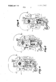
- FIG. 4 is a side elevational view, partly in section, of a typical clamping tool used in the present invention, illustrating the movable element thereof at its initial or starting position;
- FIG. 5 is a view corresponding to FIG. 4 and illustrating the movable tool element at an intermediate position prior to clamping
- FIG. 6 is a view corresponding to FIG. 4 and illustrating the movable tool element at its raised position after clamping has been completed.
- FIG. 1 is a schematic diagram of the pressure intensifier system of the present invention, and the system may, for convenient reference, be generally divided into four sections including a source of low pressure fluid indicated by dotted line 10 in FIG. 1, a hydraulic pressure intensifier unit indicated by dotted line 100, a tool indicated by dotted line 200, and a hydraulic control system indicated by dotted line 300.
- the source 10 is preferably a self-contained closed center hydraulic circuit which includes a pump 12 having an inlet line 14 leading from a reservoir 16 and an outlet line 18 leading through a one-way check valve 20 to a system feed line 22 which is also connected to an accumulator 24, the accumulator 24 preferably being of the type employing a rubber diaphragm which operates in a conventional manner to receive the output from the pump 12 and provide a source of fluid at a relatively constant pressure to the feed line 22.
- the reservoir 16 may be open to atmosphere, and a relief valve 26 is provided in a pump bypass line 28.
- the relief valve 26 is of conventional construction, and includes an adjustable spring bias 30 acting to maintain the relief valve 26 at its closed position and a pilot line 32 is provided for admitting fluid from the pump outlet line 18 to the relief valve 26 to act against the valve and urge it toward its open position in oppostion to the bias of spring 30. It will be apparent that when the pressure of the fluid fed to the relief valve through pilot line 32 provides a sufficient force to overcome the selected force exerted by spring 30, the relief valve 26 will open and the discharge from pump 12 will be by-passed back to the reservoir 16.
- the pressure intensifying unit 100 which is illustrated in greater detail in FIGS. 2 and 3, includes a housing 102 which is formed with a larger portion connected to a smaller portion by a threaded connection 102 which permits the two housing portions to be readily separated.
- the housing 102 carries therein a reciprocating member 104 provided with a relatively large operating piston 106 reciprocable in an operating cylinder 108 and connected with a relatively small intensifier piston 110 reciprocable in an intensifier cylinder 112.
- the operating piston 106 has a three-piece laminated construction with peripheral seals 114 and O-ring seals 116 being provided to prevent the leakage of fluid from one side of the operating piston 106 to the other.
- a gland 118 is provided with a plurality of annular seals 120 in contact with the exterior surface of the intensifier piston 110, and with O-ring seals 122 which prevent the leakage of fluid around the gland 118.
- the gland 118 is held in place by a cap member 124 threaded into the housing 102, and it will be readily apparent that when the upper portion of housing 102 and the cap member 124 are removed, the entire gland 118 may be removed and replaced with a new gland 118 whereby seals 120, which tend to become worn more quickly because of the high pressure exerted thereagainst, can be replaced in one simple operation rather than requiring disassembly of the intensifier piston 110 or cylinder 112 to replace worn high pressure seals 120 individually.
- the reciprocating member 104 is shown at its initial or starting position with the operating piston 106 located at the right-hand end of operating cylinder 108 adjacent a first port 126 leading into the operating cylinder 108, and a second port 128 is shown leading into the operating cylinder 108 at the other end thereof.
- pressurized hydraulic fluid is admitted through the first port 126 while the second port 128 is con nected to the reservoir whereby such pressurized fluid will cause the reciprocating member 104 to move in a first direction to the left in FIGS. 1 and 3, and to then return to its initial or starting position when second port 128 is connected to a source of pressurized fluid and first port 126 is connected to the open reservoir 16.
- the intensifier cylinder 112 is provided with an outlet 130 at the end thereof farthest from the leading end face of the intensifier piston 110, and an inlet port 132 leads into the intensifier cylinder 112 at a point adjacent the leading end face of the intensifier piston 110 when the reciprocating member 104 is at its aforesaid initial position as shown in FIGS. 1 and 3. It will be noted that the outlet 30 is always open with respect to the intensifier cylinder 112, and that the inlet port 132 is open when the reciprocating member 104 is at its initial position (FIG. 3) but is closed by the intensifier piston 110 as it moves across the inlet port 132 during movement of the reciprocating member 104.
- the aforementioned hydraulically operated tool 200 is of conventional design and is particularly well suited for clamping a cylindrical aluminum sleeve 202 about the abutting ends of two multistrand wires to join such wires together, one wire end 204 being illustrated in FIGS. 4-6.
- the tool 200 includes a fixed die member 206 and a movable die member 208 arranged to move toward the fixed die member 206 and clamp the sleeve 202 about the wire ends 204.
- the movable die member 208 is mounted on a hollow piston 210 reciprocating in a cylinder 212 having an inlet 214 leading thereto, the inlet 214 being in fluid communication with the outlet 130 of the pressure intensifying unit 100 through a line 228 as illustrated in FIG. 1.
- a spring rod 216 is anchored in the cylinder 212 by a nut 218, and extends into the hollow interior portion of the piston 210 with the top of the spring rod 216 being secured to a top biasing plate 220.
- a bottom biasing plate 222 is fixed to the piston 210 and slidable along the spring rod 216, and a biasing compression spring 224 acts between the top biasing plate 220 and bottom biasing plate 222 to urge the piston 210 and movable die member 208 attached thereto in a direction away from the fixed die members 206.
- the bottom biasing plate 222 has an opening 226 formed therein through which fluid in the cylinder 212 passes to act against the interior surface of the hollw piston 210, and it is apparent that when fluid under pressure is admitted to the cylinder 212 through inlet 214, such fluid will urge the piston 210 upwardly against the bias of compression spring 224.
- the aforementioned control system 300 includes a two-way main control valve 302 having an operating handle 302" and connected to previously described source feed line 22, and also has an exhaust line 304 leading therefrom to the reservoir 16.
- a line 306 connects the main control valve 302 with the second port 128 of intensifier unit operating cylinder 108, and another line 308 leads from the main control valve 302 to connect with the intensifier cylinder inlet 132 through a branch line 308 and to connect with a sequence valve 310 through a second branch line 308".
- a line 312 connects the sequence valve 310 with the first port 126 in the operating cylinder 108 and a by-pass line 314 having a one-way check valve 316 therein is connected between line 312 and line 308 to permit fluid to by-pass the sequence valve 310 in flowing from the operating cylinder 108 back to the reservoir 16 through the main control valve 302 as will be explained in greater detail presently.
- the sequence valve 310 includes a selectively adjustable spring bias 318 urging it toward a closed position as shown in FIG. 1, and a pilot line 320 extends from the branch line 308 to the sequence valve 310 to permit the fluid pressure in the branch line 308" to exert valve-opening force thereagainst in opposition to the urging of spring bias 318.
- the force exerted against the sequence valve 310 to maintain it at a closed position may be selected by adjusting the spring bias 318, and the sequence valve 310 will remain closed until the force imposed on the sequence valve 310 by the fluid pressure from line 320 is sufficient to overcome the forces of spring bias 318 and move the sequence valve 310 to its open position.
- a pressure relief valve 322 is located between lines 306 and 308, and it is normally maintained at a closed position by an adjustable spring bias 324 until the fluid pressure exerted by fluid passing through a pilot line 326 is adequate to overcome this spring bias 324 and open the pressure relief valve 322.
- FIG. 1 shows the pressure intensifier system of the present invention at its operating position after having just completed a working stroke of the tool 200, it being noted that the main control valve 302 is urged to the left by a spring bias 302' and will remain in this position until the main control valve 302 is manually moved toward the right by operating handle 302" against the urging of spring bias 302'.
- the intensifier cylinder 112 is connected to the reservoir 16 through inlet port 132, lines 308 and 308, main control valve 302 and exhaust line 304, and the pressure in the tool cylinder 212 is also atmospheric because the tool cylinder 212 is open to the intensifier cylinder 1 12 through tool supply line 228 and the intensifier cylinder outlet 130.
- the movable die member 208 Since there is no fluid pressure being exerted against the tool piston 210, it will be positioned at its lowermost position as shown in FIG. 4 under the urging of compression spring 224. At this lowermost position of tool piston 210, the movable die member 208 has a substantial spacing from the fixed die member 206, and the wire ends 204 and sheath 202 to be clamped can be readily placed between the spaced die members 206 and 208.
- the main control valve 302 is moved to its right-hand position against the urging of spring bias 302' by manual operation of an operating handle 302" (FIG. 2), whereupon the low pressure source fluid in feed line 22 flows through the main control valve 302 to line 308 and branch line 308' and 308", and the exhaust line 304 is connected to line 306 whereby the fluid in the operating cylinder 108 to the left of operating piston 106 is vented to the reservoir 16.
- the low pressure fluid in branch line 308" is blocked by closed sequence valve 310, and the low pressure fluid in branch line 308' flows into the intensifier cylinder 112 through inlet port 132, then through the intensifier chamber outlet port 130 and tool supply line 228 to the cylinder 212 of the tool 200.
- the low pressure source fluid acts against the tool piston 210 and has a sufficient force to overcome the bias of compression spring 224 and begin moving the piston 210 and movable die member 208 upwardly.
- the resistance offered by the compression spring 224 is relatively light, and since the low pressure source fluid is flowing into the cylinder 212 having an expanding volume as the piston 210 is being raised, the pressure of the source fluid in lines 308 and 308" is relatively low and well below the level required to open sequence valve 310 because of the preselected closing bias exerted thereon by adjustable spring 318. Accordingly, low pressure source fluid is fed directly to the tool 200 while the pressure intensifying unit 100 remains inactive, and a large volume of this low pressure source fluid is readily available to insure that an adequate quantity of fluid will be fed to the tool cylinder 212 to raise the tool piston 210 and movable die member 208 through a relatively long initial stroke as the latter moves from its FIG. 4 position to its FIG. 5 position.
- the low pressure fluid admitted through first port 126 will act against the operating piston 106 causing it to move to the left as seen in FIGS. 1 and 3, the fluid to the left of the operating piston 106 being exhausted to the reservoir 16 through port 128 and lines 306 and 304.
- This movement of the operating piston 106 also causes movement of intensifier piston 110 to the left.
- the inlet port 132 is closed by the intensifier piston 110 after which fluid pressure in the intensifier cylinder 112 is intensified or increased as it is discharged through outlet 130 to the tool cylinder 212 to act against the tool piston 210 and move the movable die member 208 to a third position as shown in FIG.
- the setting for the opening of the sequence valve 310 determines the minimum pressure of the fluid acting against the operating piston 106
- the setting for the opening of the relief valve 322 determines the maximum pressure of the fluid acting against the operating piston 106 because if the fluid pressure in line 308 and 308" exceeds the setting of the relief valve 322 it will open and by-pass fluid back to the reservoir 16 through lines 306 and 304 to thereby maintain the pressure acting against the operating piston 106 at a preselected maximum level.
- the main control valve 302 is permitted to move to the left under the influence of spring bias 302 to its position as shown in FIG. 1 whereby the source fluid from feed line 22 is applied to the right-hand side of operating piston 106 through line 306 and the left-hand side of the operating piston 106 is vented to the reservoir 16 through line 312, by-pass 314, line 308", line 308 and exhaust line 304, whereupon the operating piston 106 and intensifier piston 110 will return to their initial or starting positions as shown in FIGS. 1 and 3. As the intensifier piston 110 returns to its starting position, fluid is withdrawn from tool cylinder 212 through line 228 and outlet of the intensifier cylinder 112, and movable die member 208 will move from its FIG.
- the pressure intensifier system of the present invention can be used with a wide variety of tools and equipment, it is particularly well suited for use with clamping arrangements like tool 200, especially where it is desirable to transport the pressure intensifier system and tool from place to place, as in a service truck where space, cost, and weight limitations are important.
- the pressure intensifier system of the present invention permits the use of a relatively small pressure intensifying unit 100 because the source fluid is utilized for moving the movable die member 208 through a substantial portion of its stroke.
- the pressure required to clamp the normal variety of wire sizes encountered by the service personnel varies generally between 4,000 psi and 10,000 psi, depending upon the resistance to be encountered in moving the movable die member from its FIG. 300 position to its FIG. 6 position.
- a pump 12 having a capacity of 8-13 gals/min. with the low pressure fluid supplied by accumulator 24 having a pressure level of about 1,200 psi.
- the pressure intensifier unit 100 has an intensifying ratio of approximately II to 1 whereby the output from intensifier cylinder 112 can be slightly in excess of the aforesaid maximum 10,000 psi system pressure requirement.
- the opening of the sequence valve 310 begins the actual clamping stroke of the movable die member 208 and the maximum fluid pressure supplied to the tool 200 from the pressure intensifying unit 100 during actual clamping can be selectively varied by adjusting the spring bias 324 of relief valve 322, and, as will be seen in FIG. 2, the spring bias 324 is readily accessible for convenient adjustment.
- the relief valve 322 is set to open at 400 psi, and this pressure is increased to 4,400 psi by the pressure intensifier unit 100 by virtue of its aforementioned II to l intensification ratio.
- the relief valve 322 is set to open at 900 psi. Accordingly, when the sequence valve bias 318 is selectively adjusted to determine the pressure at which sequence valve 310 opens, the pressure relief valve bias '324 is likewise adjusted to cause the pressure relief valve 322 to open at a pressure level which is somewhat higher than that which will open sequence valve 30 and which will produce the desired maximum fluid force I required for the particular tool being used.
- the sequence valve bias 318 is selectively adjusted to determine the pressure at which sequence valve 310 opens
- the pressure relief valve bias '324 is likewise adjusted to cause the pressure relief valve 322 to open at a pressure level which is somewhat higher than that which will open sequence valve 30 and which will produce the desired maximum fluid force I required for the particular tool being used.
- pressure intensifier system of the present invention may be used with a wide variety of tools because a substantially infinite selection of tool clamping pressures may be obtained by simply adjusting the setting of the relief valve spring bias 324.
- pressure intensifying means including a reciprocating member provided with a relatively large operating piston movable in an operating chamber and connected with a relatively small intensifier piston movable in an intensifier cylinder, said reciprocating member being selectively movable by said low pressure source fluid from a starting position in a first direction to cause the pressure of the fluid in said intensifier cylinder to be intensified and being selectively movable in a second direction to return said reciprocating member to said starting position thereof, said intensifier cylinder having an inlet port located adjacent the leading end of said intensifier piston at said starting position thereof and an outlet spaced from said inlet port, said inlet port being closed by said intensifier piston as it moves across said inlet port during movement of said reciprocating member; and
- a hydraulic circuit including conduit means connecting said source to said pressure intensifying means and including selectively operable control means for sequentially:
- control means includes means for selectively setting said predetermined pressure at which said control means begins admitting said low pressure source fluid to said pressure intensifying means operating chamber.
Landscapes
- Engineering & Computer Science (AREA)
- Mechanical Engineering (AREA)
- Physics & Mathematics (AREA)
- Fluid Mechanics (AREA)
- General Engineering & Computer Science (AREA)
- Fluid-Pressure Circuits (AREA)
Abstract
A hydraulic pressure intensifier system including a source of low pressure fluid, a tool including a movable clamping element operated hydraulically by low pressure fluid from an initial position to a second position in contact with the work to be clamped by the tool and then operated by high pressure fluid to a third position during which such work is clamped, a steppedpiston hydraulic intensifying unit for selectively intensifying the low pressure fluid from the source, and a hydraulic circuit including control means for sequentially supplying low pressure source fluid to the movable clamping element to cause movement thereof from its initial position to its second position, then, in response to the fluid pressure acting against the movable element increasing to a predetermined level, supplying fluid to operate the hydraulic pressure intensifier unit which supplies fluid at an intensified pressure to act against the movable element and move it to its third position, and then venting the fluid supply to the movable element to permit it to return to its initial position under the influence of a bias.
Description
United States Patent Dixon, Jr.
HYDRAULIC PRESSURE INTENSIFIER SYSTEM Inventor: William Jennings Dixon, Jr.,
Charlotte, N.C.
Assignee: R. H. Bouligny, lnc., Charlotte, NC.
Filed: Feb. 21, 1974 Appl. No.: 444,356
US. Cl. 29/203 DT; 60/452; 92/152 Int. Cl B2lf 15/00 Field of Search 29/203; 92/152; 60/452, 60/430 References Cited UNITED STATES PATENTS Primary ExaminerLowell A. Larson Attorney, Agent, or FirmRichards, Shefte & Pinckney [57] ABSTRACT A hydraulic pressure intensifier system including a source of low pressure fluid, a tool including a movable clamping element operated hydraulically by low pressure fluid from an initial position to a second position in contact with the work to be clamped by the tool and then operated by high pressure fluid to a third position during which such work is clamped, a stepped-piston hydraulic intensifying unit for selectively intensifying the low pressure fluid from the source, and a hydraulic circuit including control means for sequentially supplying low pressure source fluid to the movable clamping, element to cause movement thereof from its initial position to its second position, then, in response to the fluid pressure acting against the movable element increasing to a predetermined level, supplying fluid to operate the hydraulic pressure intensifier unit which supplies fluid at an intensified pressure to act against the movable element and move it to its third position, and then venting the fluid supply to the movable element to permit it to return to its initial position under the influence of a bias.
11 Claims, 6 Drawing Figures W302 2 1 302 2224 2:158 218 I 306 32 H 338 310 zoo 326 -308 Q:3/
PATENTEI] JUN 1 7 I975 SHEET 1 HYDRAULIC PRESSURE INTENSIFIER SYSTEM BACKGROUND OF THE INVENTION Hydraulic intensifier systems have a wide variety of uses where it is desired to convert a high volume, low pressure source of hydraulic fluid to a low volume, high pressure supply of working fluid, and such systems frequently employ a stepped-piston hydraulic intensifying unit which utilizes the high volume, low pressure source to operate a relatively large piston which, in turn, operates a smaller piston to intensify the pressure in the cylinder of the smaller piston. A control arrangement is generally provided to cause reciprocation of the large operating piston, whereby high pressure fluid is available intermittently from the small intensifier piston.
Typical examples of such hydraulic intensifier systems are disclosed in US. Pat. No. 2,864,313, issued Dec. 16, 1958, to Dawson, and US. Pat. No. 3,207,442, issued Sept. 21, 1965, to Kessler. In the Dawson patent, a stepped-piston hydraulic intensifier is used to elevate a low pressure hydraulic fluid source to a high pressure hydraulic fluid supply which can be used to operate presses, rams and the like, and the low pressure source is admitted to the intensifier cylinder through a check valve to maintain the minimum pressure in such intensifier cylinder at a level corresponding to the low pressure of the hydraulic fluid source and to 'make up any fluid leakages in the intensifier cylinder or the circuit connecting this cylinder with the ram or other tool. It is to be noted, however, that in systems like that disclosed in Dawson, movement of the ram or other tool must follow precisely the movement of the intensifier piston because the hydraulic fluid circuit therebetween is constantly maintained at a pressure level at least as high as the low pressure source fluid and such fluid is, of course, incompressible so as to provide, in effect, a solid connection between the intensifier piston and the ram or other working element. This type of hydraulic system is satisfactory for use with hydraulic rams or the like which have a short working stroke that can be effectively handled by the low volume of high pressure fluid generated from the intensifier piston, but it is not generally satisfactory for use with tools in which the working element has a relatively long working stroke that requires a relatively large amount of working hydraulic fluid to operate the working element through such stroke because a very large hydraulic intensifier would be required to provide the volume of high pressure working fluid required to move the working element through its relatively long stroke.
A hydraulic intensifier system generally similar to that of Dawson is disclosed in the aforementioned Kessler patent wherein a reciprocating stepped-piston hydraulic intensifier is utilized as a spray gun for cleaning scale and the like from metal surfaces, the outlet of the intensifier cylinder being connected to a spray nozzle for this purpose. Low pressure source fluid is constantly fed to the intensifier cylinder and is emitted from the spray nozzle as a low pressure spray during the return movement of the intensifier piston, and a high pressure spray is emitted from the spray nozzle during the working stroke of the intensifier piston. Thus, if the Kessler hydraulic intensifier were to be used with a tool having a moving element with a relatively long working stroke, it would suffer the same disadvantages of Dawson as discussed above because it would require a very large intensifier piston to supply the volume of high pressure fluid required to operate the working element of the tool through its relatively long stroke.
In accordance with the present invention, a unique hydraulic intensifier system is provided which effectively utilizes the low pressure, high volume source of hydraulic fluid to operate the moving tool element through an initial portion of its working stroke, after which the intensified pressure is used to complete the working stroke and the moving element is then allowed to return to its starting position. Thus, a relatively small and economical hydraulic intensifying unit can be effectively used to supply a tool having a relatively large working stroke.
SUMMARY OF THE INVENTION In accordance with the present invention, a hydraulic intensifier system is provided which includes a source of low pressure fluid, pressure intensifying means which is operated by the low pressure source fluid and which acts to increase the pressure thereof, and then discharge such high pressure fluid through an outlet which is connected to a hydraulically operated tool or the like, and, a hydraulic circuit including selectively operable control means for sequentially supplying low pressure source fluid directly to the pressure intensifying means outlet whereby a low pressure, high volume fluid source is provided for the tool, then admitting low pressure source fluid to the pressure intensifying means in response to the pressure at the outlet thereof increas ing to a predetermined level to thereby operate the pressure intensifying means and cause a high pressure, low volume fluid to be fed to the tool through the intensifying means outlet, and, finally, venting the fluid supply to the tool to atmospheric pressure.
The sequential control of the fluid supplied through the pressure intensifying means outlet renders it particularly adaptable for use with a tool such as a hydraulically operated wire clamping tool, in which a movable element travels toward and away from a fixed element, and such movable element has a relatively long stroke, only a portion of which requires a high pressure operating fluid. For example, in a typical wire clamping tool, two abutting wire ends loosely encased within a cylindrical sleeve-are placed between a fixed die and a movable clamping die which have a relatively wide initial spacing therebetween to permit the material to be clamped to be readily placed between the dies, and the movable die must then move through an initial, relatively large portion of its travel with little or no resistance until the dies are in contact with the material to be clamped therebetween, after which the movable die continues to move toward the fixed die against substantial resistance to clamp the materials therebetween, and then the movable die is urged by a bias to return to its initial position for a subsequent clamping operation. The pressure intensifier system of the present invention sequentially supplies low pressure, high volume source fluid to the movable die to cause movement thereof through the aforesaid initial portion of its movement toward the fixed die, then supplies high pressure, low volume fluid to the movable die to cause movement thereof through the final or clamping portion of its movement toward the fixed die, and, finally, vents the fluid acting against the movable die to permit it to return to its initial position substantially spaced from the fixed die.
The aforesaid pressure intensifying means of the present invention includes a hydraulically operated reciprocating member provided with a relatively large operating piston reciprocating in an operating cylinder connected to a relatively small intensifier piston recip rocating in an intensifier cylinder from which the outlet to the tool extends. A fluid inlet port is provided in the intensifier cylinder at a pointj'adjacent the end of the intensifier piston when it is positioned to begin its intensifying stroke, said inlet port being closed by the intensifying piston as it moves across the inlet port during reciprocating movement thereof.
Low pressure source fluid is initially admitted by the control means to the inlet port where it passes through the intensifier cylinder and through the outlet thereof until a predetermined pressure level is reached in the fluid supplied to the tool, as would occur when the movable tool element completes the aforesaid initial portion of its travel toward the fixed tool element, and then a normally closed sequence valve is opened to permit low pressure source fluid to be admitted to the pressure intensifying means operating chamber to cause the intensifier piston to increase or intensify the pressure of the fluid in the intensifier cylinder and dis charge such fluid through the outlet to move the movable tool element through the final or clamping portion of its movement. The maximum level of the fluid pressure acting against the movable tool element may be selectively regulated by providing a relief valve in the supply system which opens at a pre-set pressure level to by-pass fluid back to a reservoir whereby such relief valve acts more or less as a throttle valve which selectively determines the maximum pressure level in the system. A main control valve then reverses the flow of low pressure fluid to the operating chamber of the pressure intensifying means to return the reciprocating member to its starting position and connects the intensifier cylinder inlet to an open reservoir whereupon the fluid supply to the tool will be vented through such inlet when the intensifier piston opens such inlet, and the movable tool element can then return to its initial position under the urging of the bias applied thereto. Thus, the initial portion of the travel of the movable tool element toward the fixed tool element is caused by the low pressure source fluid before the pressure intensifying reciprocating member begins its pressure intensifying operation, and the return portion of the travel of the movable tool element is permitted after the pressure intensifying reciprocating member has returned to its initial or starting position.
The aforementioned sequence valve is normally urged towards its closed position by a bias, and a fluid connection is provided between the aforesaid intensifier cylinder and the sequence valve to permit the fluid pressure in the intensifier cylinder to act against the sequence valve and urge it toward its open position in opposition to the aforesaid valve closing bias. The force exerted by the valve closing bias can be selectively regulated whereby the fluid pressure required to open the sequence valve can be regulated accordingly.
BRIEF DESCRIPTION OF THE DRAWINGS FIG. 1 is a schematic diagram of the pressure intensifier system of the present invention;
FIG. 2 is a front end view of the pressure intensifying unit and control valve housing employed in the present invention;
FIG. 3 is a sectional view taken along line 3-3 in FIG. 2;
FIG. 4 is a side elevational view, partly in section, of a typical clamping tool used in the present invention, illustrating the movable element thereof at its initial or starting position;
FIG. 5 is a view corresponding to FIG. 4 and illustrating the movable tool element at an intermediate position prior to clamping; and
FIG. 6 is a view corresponding to FIG. 4 and illustrating the movable tool element at its raised position after clamping has been completed.
DESCRIPTION OF THE PREFERRED EMBODIMENTS Looking now in greater detail at the accompanying drawings, FIG. 1 is a schematic diagram of the pressure intensifier system of the present invention, and the system may, for convenient reference, be generally divided into four sections including a source of low pressure fluid indicated by dotted line 10 in FIG. 1, a hydraulic pressure intensifier unit indicated by dotted line 100, a tool indicated by dotted line 200, and a hydraulic control system indicated by dotted line 300.
Although any convenient source of low pressure hydraulic fluid may be employed in the intensifier system of the present invention, the source 10 is preferably a self-contained closed center hydraulic circuit which includes a pump 12 having an inlet line 14 leading from a reservoir 16 and an outlet line 18 leading through a one-way check valve 20 to a system feed line 22 which is also connected to an accumulator 24, the accumulator 24 preferably being of the type employing a rubber diaphragm which operates in a conventional manner to receive the output from the pump 12 and provide a source of fluid at a relatively constant pressure to the feed line 22. The reservoir 16 may be open to atmosphere, and a relief valve 26 is provided in a pump bypass line 28. The relief valve 26 is of conventional construction, and includes an adjustable spring bias 30 acting to maintain the relief valve 26 at its closed position and a pilot line 32 is provided for admitting fluid from the pump outlet line 18 to the relief valve 26 to act against the valve and urge it toward its open position in oppostion to the bias of spring 30. It will be apparent that when the pressure of the fluid fed to the relief valve through pilot line 32 provides a sufficient force to overcome the selected force exerted by spring 30, the relief valve 26 will open and the discharge from pump 12 will be by-passed back to the reservoir 16.
The pressure intensifying unit 100, which is illustrated in greater detail in FIGS. 2 and 3, includes a housing 102 which is formed with a larger portion connected to a smaller portion by a threaded connection 102 which permits the two housing portions to be readily separated. The housing 102 carries therein a reciprocating member 104 provided with a relatively large operating piston 106 reciprocable in an operating cylinder 108 and connected with a relatively small intensifier piston 110 reciprocable in an intensifier cylinder 112. The operating piston 106 has a three-piece laminated construction with peripheral seals 114 and O-ring seals 116 being provided to prevent the leakage of fluid from one side of the operating piston 106 to the other. To prevent fluid from flowing along the intensifier piston 110, a gland 118 is provided with a plurality of annular seals 120 in contact with the exterior surface of the intensifier piston 110, and with O-ring seals 122 which prevent the leakage of fluid around the gland 118. The gland 118 is held in place by a cap member 124 threaded into the housing 102, and it will be readily apparent that when the upper portion of housing 102 and the cap member 124 are removed, the entire gland 118 may be removed and replaced with a new gland 118 whereby seals 120, which tend to become worn more quickly because of the high pressure exerted thereagainst, can be replaced in one simple operation rather than requiring disassembly of the intensifier piston 110 or cylinder 112 to replace worn high pressure seals 120 individually.
In FIGS. 1 and 3, the reciprocating member 104 is shown at its initial or starting position with the operating piston 106 located at the right-hand end of operating cylinder 108 adjacent a first port 126 leading into the operating cylinder 108, and a second port 128 is shown leading into the operating cylinder 108 at the other end thereof. As will be described in greater detail below, pressurized hydraulic fluid is admitted through the first port 126 while the second port 128 is con nected to the reservoir whereby such pressurized fluid will cause the reciprocating member 104 to move in a first direction to the left in FIGS. 1 and 3, and to then return to its initial or starting position when second port 128 is connected to a source of pressurized fluid and first port 126 is connected to the open reservoir 16.
The intensifier cylinder 112 is provided with an outlet 130 at the end thereof farthest from the leading end face of the intensifier piston 110, and an inlet port 132 leads into the intensifier cylinder 112 at a point adjacent the leading end face of the intensifier piston 110 when the reciprocating member 104 is at its aforesaid initial position as shown in FIGS. 1 and 3. It will be noted that the outlet 30 is always open with respect to the intensifier cylinder 112, and that the inlet port 132 is open when the reciprocating member 104 is at its initial position (FIG. 3) but is closed by the intensifier piston 110 as it moves across the inlet port 132 during movement of the reciprocating member 104.
The aforementioned hydraulically operated tool 200, as best seen in FIGS. 4-6, is of conventional design and is particularly well suited for clamping a cylindrical aluminum sleeve 202 about the abutting ends of two multistrand wires to join such wires together, one wire end 204 being illustrated in FIGS. 4-6. The tool 200 includes a fixed die member 206 and a movable die member 208 arranged to move toward the fixed die member 206 and clamp the sleeve 202 about the wire ends 204. The movable die member 208 is mounted on a hollow piston 210 reciprocating in a cylinder 212 having an inlet 214 leading thereto, the inlet 214 being in fluid communication with the outlet 130 of the pressure intensifying unit 100 through a line 228 as illustrated in FIG. 1. A spring rod 216 is anchored in the cylinder 212 by a nut 218, and extends into the hollow interior portion of the piston 210 with the top of the spring rod 216 being secured to a top biasing plate 220. A bottom biasing plate 222 is fixed to the piston 210 and slidable along the spring rod 216, and a biasing compression spring 224 acts between the top biasing plate 220 and bottom biasing plate 222 to urge the piston 210 and movable die member 208 attached thereto in a direction away from the fixed die members 206. The bottom biasing plate 222 has an opening 226 formed therein through which fluid in the cylinder 212 passes to act against the interior surface of the hollw piston 210, and it is apparent that when fluid under pressure is admitted to the cylinder 212 through inlet 214, such fluid will urge the piston 210 upwardly against the bias of compression spring 224.
The aforementioned control system 300 includes a two-way main control valve 302 having an operating handle 302" and connected to previously described source feed line 22, and also has an exhaust line 304 leading therefrom to the reservoir 16. A line 306 connects the main control valve 302 with the second port 128 of intensifier unit operating cylinder 108, and another line 308 leads from the main control valve 302 to connect with the intensifier cylinder inlet 132 through a branch line 308 and to connect with a sequence valve 310 through a second branch line 308". A line 312 connects the sequence valve 310 with the first port 126 in the operating cylinder 108 and a by-pass line 314 having a one-way check valve 316 therein is connected between line 312 and line 308 to permit fluid to by-pass the sequence valve 310 in flowing from the operating cylinder 108 back to the reservoir 16 through the main control valve 302 as will be explained in greater detail presently.
The sequence valve 310 includes a selectively adjustable spring bias 318 urging it toward a closed position as shown in FIG. 1, and a pilot line 320 extends from the branch line 308 to the sequence valve 310 to permit the fluid pressure in the branch line 308" to exert valve-opening force thereagainst in opposition to the urging of spring bias 318. Thus, the force exerted against the sequence valve 310 to maintain it at a closed position may be selected by adjusting the spring bias 318, and the sequence valve 310 will remain closed until the force imposed on the sequence valve 310 by the fluid pressure from line 320 is sufficient to overcome the forces of spring bias 318 and move the sequence valve 310 to its open position. Similarly, a pressure relief valve 322 is located between lines 306 and 308, and it is normally maintained at a closed position by an adjustable spring bias 324 until the fluid pressure exerted by fluid passing through a pilot line 326 is suficient to overcome this spring bias 324 and open the pressure relief valve 322.
The schematic diagram in FIG. 1 shows the pressure intensifier system of the present invention at its operating position after having just completed a working stroke of the tool 200, it being noted that the main control valve 302 is urged to the left by a spring bias 302' and will remain in this position until the main control valve 302 is manually moved toward the right by operating handle 302" against the urging of spring bias 302'. In this static condition of the system, the intensifier cylinder 112 is connected to the reservoir 16 through inlet port 132, lines 308 and 308, main control valve 302 and exhaust line 304, and the pressure in the tool cylinder 212 is also atmospheric because the tool cylinder 212 is open to the intensifier cylinder 1 12 through tool supply line 228 and the intensifier cylinder outlet 130. Since there is no fluid pressure being exerted against the tool piston 210, it will be positioned at its lowermost position as shown in FIG. 4 under the urging of compression spring 224. At this lowermost position of tool piston 210, the movable die member 208 has a substantial spacing from the fixed die member 206, and the wire ends 204 and sheath 202 to be clamped can be readily placed between the spaced die members 206 and 208.
To begin operation of the pressure intensifier system, the main control valve 302 is moved to its right-hand position against the urging of spring bias 302' by manual operation of an operating handle 302" (FIG. 2), whereupon the low pressure source fluid in feed line 22 flows through the main control valve 302 to line 308 and branch line 308' and 308", and the exhaust line 304 is connected to line 306 whereby the fluid in the operating cylinder 108 to the left of operating piston 106 is vented to the reservoir 16. The low pressure fluid in branch line 308" is blocked by closed sequence valve 310, and the low pressure fluid in branch line 308' flows into the intensifier cylinder 112 through inlet port 132, then through the intensifier chamber outlet port 130 and tool supply line 228 to the cylinder 212 of the tool 200. The low pressure source fluid acts against the tool piston 210 and has a sufficient force to overcome the bias of compression spring 224 and begin moving the piston 210 and movable die member 208 upwardly. The resistance offered by the compression spring 224 is relatively light, and since the low pressure source fluid is flowing into the cylinder 212 having an expanding volume as the piston 210 is being raised, the pressure of the source fluid in lines 308 and 308" is relatively low and well below the level required to open sequence valve 310 because of the preselected closing bias exerted thereon by adjustable spring 318. Accordingly, low pressure source fluid is fed directly to the tool 200 while the pressure intensifying unit 100 remains inactive, and a large volume of this low pressure source fluid is readily available to insure that an adequate quantity of fluid will be fed to the tool cylinder 212 to raise the tool piston 210 and movable die member 208 through a relatively long initial stroke as the latter moves from its FIG. 4 position to its FIG. 5 position.
When the movable die member 208 reaches its second position as shown in FIG. 5, the wire ends 204 and sleeve 202 are in contact with both the fixed die member 206 and the movable die member 208 whereby further upward movement of the movable die member 208 encounters substantial resistance. Therefore, the pressure of the source fluid in tool supply line 228, intensifier cylinder 112, and lines 308, and 308' and 308" begins to increase, but the maximum pressure which can be developed solely by the source is insufficient to overcome the resistance encountered by the movable die member 208 as indicated above. However, when the fluid pressure in line 308" increases to a preselected level as determined by the adjustment of the sequence valve spring bias 318, such fluid pressure will overcome the spring bias 318 and open the sequence valve 310 whereby the source fluid will be admitted to the operating cylinder 108 of the pressure intensifying unit 100 through line 312 and first port 126.
The low pressure fluid admitted through first port 126 will act against the operating piston 106 causing it to move to the left as seen in FIGS. 1 and 3, the fluid to the left of the operating piston 106 being exhausted to the reservoir 16 through port 128 and lines 306 and 304. This movement of the operating piston 106 also causes movement of intensifier piston 110 to the left. During the initial portion of this movement of the intensifier piston 110, the inlet port 132 is closed by the intensifier piston 110 after which fluid pressure in the intensifier cylinder 112 is intensified or increased as it is discharged through outlet 130 to the tool cylinder 212 to act against the tool piston 210 and move the movable die member 208 to a third position as shown in FIG. 6 during which the sleeve 202 is securely clamped by the die members 206 and 208 about the wire ends 204. It is to be recognized, of course, that the 7 degree of pressure increase obtained from the pressure intensifier unit depends upon the comparative areas of the operating piston 106 and the intensifier piston 110, and a proper selection of such piston sizes, taking into consideration the given source pressure, will provide the pressure necessary to move the movable die member 208 against fixed die member 206 in clamping the sleeve 202 about the wire ends 204. Also, even though the movable die member 208 only moves a relatively short distance between its second (FIG. 5) and third (FIG. 6) positions, a relatively long stroke of the intensifier piston is required because of the difference in size between tool piston 210 and intensifier piston 110. Therefore, it will be appreciated that only a relatively small pressure intensifier unit 100 can be effectively used with a clamping tool having a long movable die member stroke because low pressure fluid is used to move the movable die member 208 during a substantial portion of its stroke, and the pressure intensifying unit 100 if used only when a high pressure force is required during actual clamping of the sleeve 202 and wire ends 204.
It is also to be noted that while the setting for the opening of the sequence valve 310 determines the minimum pressure of the fluid acting against the operating piston 106, the setting for the opening of the relief valve 322 determines the maximum pressure of the fluid acting against the operating piston 106 because if the fluid pressure in line 308 and 308" exceeds the setting of the relief valve 322 it will open and by-pass fluid back to the reservoir 16 through lines 306 and 304 to thereby maintain the pressure acting against the operating piston 106 at a preselected maximum level. By determining the maximum pressure acting against the operating piston 106 in this manner, it will be apparent that the maximum pressure of the intensified fluid pressure acting against the tool 200 will likewise be determined even though it will be much greater because of the intensification ratio of the operating piston 106 and intensifier piston 110.
After the aforesaid clamping action is completed, the main control valve 302 is permitted to move to the left under the influence of spring bias 302 to its position as shown in FIG. 1 whereby the source fluid from feed line 22 is applied to the right-hand side of operating piston 106 through line 306 and the left-hand side of the operating piston 106 is vented to the reservoir 16 through line 312, by-pass 314, line 308", line 308 and exhaust line 304, whereupon the operating piston 106 and intensifier piston 110 will return to their initial or starting positions as shown in FIGS. 1 and 3. As the intensifier piston 110 returns to its starting position, fluid is withdrawn from tool cylinder 212 through line 228 and outlet of the intensifier cylinder 112, and movable die member 208 will move from its FIG. 6 position to its FIG. 5 position. Additionally, when the intensifier piston 110 moves to the right sufficiently to open inlet port 132, the intensifier cylinder 112 is vented to the reservoir 16 through port 132, lines 308', 308 and 304, whereby all fluid pressure in tool cylinder 212 is also vented to the reservoir 16 and the movable tool will move, under the urging of compression spring 224, from its FIG. position to its initial position as shown in FIG. 4. It is to be noted that if the tool cylinder 212 was not vented at the completion of the movement of the intensifier piston 1 10, the movable die member 208 could not move to its FIG. 4 position.
While it is to be understood that the pressure intensifier system of the present invention can be used with a wide variety of tools and equipment, it is particularly well suited for use with clamping arrangements like tool 200, especially where it is desirable to transport the pressure intensifier system and tool from place to place, as in a service truck where space, cost, and weight limitations are important. As pointed out above, the pressure intensifier system of the present invention permits the use of a relatively small pressure intensifying unit 100 because the source fluid is utilized for moving the movable die member 208 through a substantial portion of its stroke.
In a typical pressure intensifier system carried in trucks for serving power lines, the pressure required to clamp the normal variety of wire sizes encountered by the service personnel varies generally between 4,000 psi and 10,000 psi, depending upon the resistance to be encountered in moving the movable die member from its FIG. 300 position to its FIG. 6 position. To obtain this pressure range, it has been found satisfactory to use a pump 12 having a capacity of 8-13 gals/min. with the low pressure fluid supplied by accumulator 24 having a pressure level of about 1,200 psi. The pressure intensifier unit 100 has an intensifying ratio of approximately II to 1 whereby the output from intensifier cylinder 112 can be slightly in excess of the aforesaid maximum 10,000 psi system pressure requirement. The opening of the sequence valve 310 (e.g. at 300 psi) begins the actual clamping stroke of the movable die member 208 and the maximum fluid pressure supplied to the tool 200 from the pressure intensifying unit 100 during actual clamping can be selectively varied by adjusting the spring bias 324 of relief valve 322, and, as will be seen in FIG. 2, the spring bias 324 is readily accessible for convenient adjustment. Thus, when a tool clamping pressure of 4,400 psi is required, the relief valve 322 is set to open at 400 psi, and this pressure is increased to 4,400 psi by the pressure intensifier unit 100 by virtue of its aforementioned II to l intensification ratio. If a tool clamping pressure of 9,900 psi is required, the relief valve 322 is set to open at 900 psi. Accordingly, when the sequence valve bias 318 is selectively adjusted to determine the pressure at which sequence valve 310 opens, the pressure relief valve bias '324 is likewise adjusted to cause the pressure relief valve 322 to open at a pressure level which is somewhat higher than that which will open sequence valve 30 and which will produce the desired maximum fluid force I required for the particular tool being used. Thus, the
pressure intensifier system of the present invention may be used with a wide variety of tools because a substantially infinite selection of tool clamping pressures may be obtained by simply adjusting the setting of the relief valve spring bias 324.
The present invention has been described in detail above for purposes of illustration only and is not intended to be limited by this description or otherwise to exclude any variation or equivalent arrangement that would be apparent from, or reasonably suggested by, the foregoing disclosure to the skill of the art.
I claim: 1. A hydraulic pressure intensifier system for use with 5 hydraulically operated tool means and the like, said system including:
a. a source of low pressure hydraulic fluid;
b. pressure intensifying means including a reciprocating member provided with a relatively large operating piston movable in an operating chamber and connected with a relatively small intensifier piston movable in an intensifier cylinder, said reciprocating member being selectively movable by said low pressure source fluid from a starting position in a first direction to cause the pressure of the fluid in said intensifier cylinder to be intensified and being selectively movable in a second direction to return said reciprocating member to said starting position thereof, said intensifier cylinder having an inlet port located adjacent the leading end of said intensifier piston at said starting position thereof and an outlet spaced from said inlet port, said inlet port being closed by said intensifier piston as it moves across said inlet port during movement of said reciprocating member; and
c. a hydraulic circuit including conduit means connecting said source to said pressure intensifying means and including selectively operable control means for sequentially:
i. admitting said low pressure source fluid solely to said pressure intensifying means outlet for supplying said tool means;
ii. then admitting said low pressure source fluid to said pressure intensifying means operating chamber when the fluid pressure at said outlet increases to a predetermined level to move said reciprocating member in said first direction thereof and causefluid at an increased pressure to be dischargedthrough said outlet to said tool;
iii. then admitting said low pressure source fluid to said operating chamber to move said reciprocating member in said second direction thereof to cause fluid to be withdrawn from said tool through said outlet; and
iv. then venting said outlet to atmospheric pressure. 7
2. A hydraulic pressure intensifier system as defined in claim 1 and further characterized in that said control means includes means for selectively setting said predetermined pressure at which said control means begins admitting said low pressure source fluid to said pressure intensifying means operating chamber.
3. A hydraulic pressure intensifier system as defined in claim 1 and further characterized in that said control means includes relief valve means in said hydraulic circuit for determining the maximum pressure of said fluid being discharged through said outlet of said pressure intensifying means.
4. A hydraulic pressure intensifier system as defined in claim 3 and further characterized in that said relief valve means determines the maximum pressure of said fluid being discharged through said pressure intensify ing means outlet by determining the maximum pressure of the fluid which is admitted to said pressure intensifying means, and in that said relief valve means includes selectively adjustable means for varying said maximum pressure of the fluid which is admitted to said pressure intensifying means.
5. A hydraulic pressure intensifier system as defined in claim 1 and further characterized in that said selectively operable control means includes sequence valve means located in said conduit means for controlling the flow of said low pressure fluid to said operating cylinder which causes said movement of said reciprocating member in said first direction thereof, said sequence valve means being normally closed to prevent said flow of said low pressure fluid to said operating cylinder and including valve opening means responsive to the pressure in said intensifier cylinder for opening said sequence valve means when said pressure in said intensifier cylinder increases to a predetermined level.
6. A hydraulic pressure intensifier system as defined in claim 5 and further characterized in that said sequence valve means includes biasing means for urging said sequence valve means toward its closed position, and includes a direct connectionwith said intensifier cylinder to permit the pressure therein to be transmitted to said sequence valve means for urging said sequence valve means toward its open position in opposition to said biasing means.
7. A hydraulic pressure intensifier system as defined in claim 6 and further characterized in that said sequence valve means includes selectively adjustable means for varying the force exerted by said biasing means in urging said sequence valve means toward its closed position.
8. A hydraulic pressure intensifier system as defined in claim 5 and further characterized in that said control means includes a main control valve connected to said source by a first fluid line, connected to a reservoir by a second fluid line, connected by a third fluid line directly to said operating cylinder at the end thereof adjacent the position of said operating piston when it begins to move in said second direction thereof, and connected by a fourth fluid line to said intensifier cylinder and to the other end of said operating cylinder through said sequence valve means, said main control valve being selectively operable between a first position connecting said first fluid line to said fourth fluid line and connecting said second fluid line to said third fluid line and a second position connecting said first fluid line to said third fluid line and connecting said second fluid line to said fourth fluid line, and in that a by-pass fluid line is provided in said fourth fluid line around said sequence valve means and includes a one-way check valve arranged to permit fluid flow from said operating cylinder to said reservoir when said main control valve is at second position thereof.
9. A hydraulic pressure intensifier system as defined in claim 1 and further characterized in that said outlet from said pressure intensifying means is connected by a supply line to a hydraulically operated tool which includes a movable element, said movable element being biased in one direction of movement, and being urged in the opposite direction of movement by the fluid supplied to said tool through said supply line and acting against said movable element.
10. A hydraulic intensifier system as defined in claim 9 and further characterized in that said low pressure fluid from said source which is admitted to said pressure intensifying means outlet and fed to said tool through said supply line to act against said movable element provides sufficient force to overcome said movable element bias and cause movement of said movable element in said opposite direction of movement.
11. A hydraulic pressure intensifier system as defined in claim 1 and further characterized in that said outlet from said pressure intensifying means is connected by a supply line to a hydraulically operated tool which includes a pair of operating elements adapted to clamp work means therebetween, at least one of said elements being arranged to move with respect to the other from an initial position spaced from said other element with said work means out of contact with at least one of said elements, then to a second position closer to said other element with said work means in contact with both of said elements, then to third position still closer to said other element during which a clamping force is exerted on said work means by said elements, and finally to return to said initial position, said elements being biased away from one another.
Claims (11)
1. A hydraulic pressure intensifier system for use with hydraulically operated tool means and the like, said system including: a. a source of low pressure hydraulic fluid; b. pressure intensifying means including a reciprocating member provided with a relatively large operating piston movable in an operating chamber and connected with a relatively small intensifier piston movable in an intensifier cylinder, said reciprocating member being selectively movable by said low pressure source fluid from a starting position in a first direction to cause the pressure of the fluid in said intensifier cylinder to be intensified and being selectively movable in a second direction to return said reciprocating member to said starting position thereof, said intensifier cylinder having an inlet port located adjacent the leading end of said intensifier piston at said starting position thereof and an outlet spaced from said inlet port, said inlet port being closed by said intensifier piston as it moves across said inlet port during movement of said reciprocating member; and c. a hydraulic circuit including conduit means connecting said source to said pressure intensifying means and including selectively operable control means for sequentially: i. admitting said low pressure source fluid solely to said pressure intensifying means outlet for supplying said tool means; ii. then admitting said low pressure source fluid to said pressure intensifying means operating chamber when the fluid pressure at said outlet increases to a predetermined level to move said reciprocating member in said first direction thereof and cause fluid at an increased pressure to be discharged through said outlet to said tool; iii. then admitting said low pressure source fluid to said operating chamber to move said reciprocating member in said second direction thereof to cause fluid to be withdrawn from said tool through said outlet; and iv. then venting said outlet to atmospheric pressure.
2. A hydraulic pressure intensifier system as defined in claim 1 and further characterized in that said control means includes means for selectively setting said predetermined pressure at which said control means begins admitting said low pressure source fluid to said pressure intensifying means operating chamber.
3. A hydraulic pressure intensifier system as defined in claim 1 and further characterized in thAt said control means includes relief valve means in said hydraulic circuit for determining the maximum pressure of said fluid being discharged through said outlet of said pressure intensifying means.
4. A hydraulic pressure intensifier system as defined in claim 3 and further characterized in that said relief valve means determines the maximum pressure of said fluid being discharged through said pressure intensifying means outlet by determining the maximum pressure of the fluid which is admitted to said pressure intensifying means, and in that said relief valve means includes selectively adjustable means for varying said maximum pressure of the fluid which is admitted to said pressure intensifying means.
5. A hydraulic pressure intensifier system as defined in claim 1 and further characterized in that said selectively operable control means includes sequence valve means located in said conduit means for controlling the flow of said low pressure fluid to said operating cylinder which causes said movement of said reciprocating member in said first direction thereof, said sequence valve means being normally closed to prevent said flow of said low pressure fluid to said operating cylinder and including valve opening means responsive to the pressure in said intensifier cylinder for opening said sequence valve means when said pressure in said intensifier cylinder increases to a predetermined level.
6. A hydraulic pressure intensifier system as defined in claim 5 and further characterized in that said sequence valve means includes biasing means for urging said sequence valve means toward its closed position, and includes a direct connection with said intensifier cylinder to permit the pressure therein to be transmitted to said sequence valve means for urging said sequence valve means toward its open position in opposition to said biasing means.
7. A hydraulic pressure intensifier system as defined in claim 6 and further characterized in that said sequence valve means includes selectively adjustable means for varying the force exerted by said biasing means in urging said sequence valve means toward its closed position.
8. A hydraulic pressure intensifier system as defined in claim 5 and further characterized in that said control means includes a main control valve connected to said source by a first fluid line, connected to a reservoir by a second fluid line, connected by a third fluid line directly to said operating cylinder at the end thereof adjacent the position of said operating piston when it begins to move in said second direction thereof, and connected by a fourth fluid line to said intensifier cylinder and to the other end of said operating cylinder through said sequence valve means, said main control valve being selectively operable between a first position connecting said first fluid line to said fourth fluid line and connecting said second fluid line to said third fluid line and a second position connecting said first fluid line to said third fluid line and connecting said second fluid line to said fourth fluid line, and in that a by-pass fluid line is provided in said fourth fluid line around said sequence valve means and includes a one-way check valve arranged to permit fluid flow from said operating cylinder to said reservoir when said main control valve is at second position thereof.
9. A hydraulic pressure intensifier system as defined in claim 1 and further characterized in that said outlet from said pressure intensifying means is connected by a supply line to a hydraulically operated tool which includes a movable element, said movable element being biased in one direction of movement, and being urged in the opposite direction of movement by the fluid supplied to said tool through said supply line and acting against said movable element.
10. A hydraulic intensifier system as defined in claim 9 and further characterized in that said low pressure fluid from said source which is admitted to said pressure intensifying means outlet and fed to said Tool through said supply line to act against said movable element provides sufficient force to overcome said movable element bias and cause movement of said movable element in said opposite direction of movement.
11. A hydraulic pressure intensifier system as defined in claim 1 and further characterized in that said outlet from said pressure intensifying means is connected by a supply line to a hydraulically operated tool which includes a pair of operating elements adapted to clamp work means therebetween, at least one of said elements being arranged to move with respect to the other from an initial position spaced from said other element with said work means out of contact with at least one of said elements, then to a second position closer to said other element with said work means in contact with both of said elements, then to third position still closer to said other element during which a clamping force is exerted on said work means by said elements, and finally to return to said initial position, said elements being biased away from one another.
Priority Applications (1)
| Application Number | Priority Date | Filing Date | Title |
|---|---|---|---|
| US444356A US3889340A (en) | 1974-02-21 | 1974-02-21 | Hydraulic pressure intensifier system |
Applications Claiming Priority (1)
| Application Number | Priority Date | Filing Date | Title |
|---|---|---|---|
| US444356A US3889340A (en) | 1974-02-21 | 1974-02-21 | Hydraulic pressure intensifier system |
Publications (1)
| Publication Number | Publication Date |
|---|---|
| US3889340A true US3889340A (en) | 1975-06-17 |
Family
ID=23764562
Family Applications (1)
| Application Number | Title | Priority Date | Filing Date |
|---|---|---|---|
| US444356A Expired - Lifetime US3889340A (en) | 1974-02-21 | 1974-02-21 | Hydraulic pressure intensifier system |
Country Status (1)
| Country | Link |
|---|---|
| US (1) | US3889340A (en) |
Cited By (10)
| Publication number | Priority date | Publication date | Assignee | Title |
|---|---|---|---|---|
| US4089170A (en) * | 1977-05-09 | 1978-05-16 | Caterpillar Tractor Co. | Power conservation means for variable displacement pump fluid supply system |
| US4385514A (en) * | 1981-07-08 | 1983-05-31 | Mcinerney Spring & Wire Company | Pipe assembly tool |
| US6273686B1 (en) * | 1999-01-29 | 2001-08-14 | A. Roemheld Gmbh & Co Kg | Apparatus and method for controlling a rated system pressure |
| US20050178121A1 (en) * | 2004-02-16 | 2005-08-18 | Leif Hansen | Hydraulic tool |
| US20060245881A1 (en) * | 2005-02-04 | 2006-11-02 | Biggerstaff Jimmy M | Priority hydraulic flow diverter control assembly |
| WO2011048271A1 (en) * | 2009-10-20 | 2011-04-28 | Mikko Junttila | Pressure transformation method and device for its implementation |
| US20130340223A1 (en) * | 2012-06-25 | 2013-12-26 | Hubbell Incorporated | Bucket truck intensifier |
| US20140283512A1 (en) * | 2013-03-25 | 2014-09-25 | Minibooster Hydraulics A/S | Hydraulic system |
| US11542961B1 (en) * | 2021-10-25 | 2023-01-03 | Deere & Company | Fluid pressure boost system and method |
| US20230131740A1 (en) * | 2021-10-25 | 2023-04-27 | Deere & Company | Fluid pressure boost system and method |
Citations (4)
| Publication number | Priority date | Publication date | Assignee | Title |
|---|---|---|---|---|
| US2403912A (en) * | 1944-01-17 | 1946-07-16 | Link Engineering Co | Press operating device |
| US2765625A (en) * | 1952-06-12 | 1956-10-09 | Charles H Hart | Air-hydraulic booster |
| US3423815A (en) * | 1966-10-13 | 1969-01-28 | Etc Inc | Fluid-actuated crimping press |
| US3619885A (en) * | 1968-11-20 | 1971-11-16 | Novopress Gmbh & Co Kg | Variable-diameter crimping tool |
-
1974
- 1974-02-21 US US444356A patent/US3889340A/en not_active Expired - Lifetime
Patent Citations (4)
| Publication number | Priority date | Publication date | Assignee | Title |
|---|---|---|---|---|
| US2403912A (en) * | 1944-01-17 | 1946-07-16 | Link Engineering Co | Press operating device |
| US2765625A (en) * | 1952-06-12 | 1956-10-09 | Charles H Hart | Air-hydraulic booster |
| US3423815A (en) * | 1966-10-13 | 1969-01-28 | Etc Inc | Fluid-actuated crimping press |
| US3619885A (en) * | 1968-11-20 | 1971-11-16 | Novopress Gmbh & Co Kg | Variable-diameter crimping tool |
Cited By (18)
| Publication number | Priority date | Publication date | Assignee | Title |
|---|---|---|---|---|
| US4089170A (en) * | 1977-05-09 | 1978-05-16 | Caterpillar Tractor Co. | Power conservation means for variable displacement pump fluid supply system |
| US4385514A (en) * | 1981-07-08 | 1983-05-31 | Mcinerney Spring & Wire Company | Pipe assembly tool |
| US6273686B1 (en) * | 1999-01-29 | 2001-08-14 | A. Roemheld Gmbh & Co Kg | Apparatus and method for controlling a rated system pressure |
| DE102004007684C5 (en) * | 2004-02-16 | 2010-01-07 | Minibooster Hydraulics A/S | Portable hydraulic tool |
| DE102004007684A1 (en) * | 2004-02-16 | 2005-09-22 | Minibooster Hydraulics A/S | Hydraulic tool |
| US7204087B2 (en) | 2004-02-16 | 2007-04-17 | Minibooster Hydraulics A/S | Hydraulic tool |
| DE102004007684B4 (en) * | 2004-02-16 | 2008-06-12 | Minibooster Hydraulics A/S | Portable hydraulic tool |
| US20050178121A1 (en) * | 2004-02-16 | 2005-08-18 | Leif Hansen | Hydraulic tool |
| US20060245881A1 (en) * | 2005-02-04 | 2006-11-02 | Biggerstaff Jimmy M | Priority hydraulic flow diverter control assembly |
| US7927060B2 (en) * | 2005-02-04 | 2011-04-19 | Bayne Machine Works, Inc. | Priority hydraulic flow diverter control assembly |
| WO2011048271A1 (en) * | 2009-10-20 | 2011-04-28 | Mikko Junttila | Pressure transformation method and device for its implementation |
| US20130340223A1 (en) * | 2012-06-25 | 2013-12-26 | Hubbell Incorporated | Bucket truck intensifier |
| US9205541B2 (en) * | 2012-06-25 | 2015-12-08 | Hubbell Incorporated | Bucket truck intensifier |
| US20140283512A1 (en) * | 2013-03-25 | 2014-09-25 | Minibooster Hydraulics A/S | Hydraulic system |
| US10337535B2 (en) * | 2013-03-25 | 2019-07-02 | Minibooster Hydraulics A/S | Hydraulic system |
| US11542961B1 (en) * | 2021-10-25 | 2023-01-03 | Deere & Company | Fluid pressure boost system and method |
| US20230131740A1 (en) * | 2021-10-25 | 2023-04-27 | Deere & Company | Fluid pressure boost system and method |
| US11808289B2 (en) * | 2021-10-25 | 2023-11-07 | Deere & Company | Fluid pressure boost system and method |
Similar Documents
| Publication | Publication Date | Title |
|---|---|---|
| US2192778A (en) | Drawing press | |
| US4271671A (en) | Two step pressure intensifier system | |
| US4170876A (en) | Method and apparatus for controlling a press plunger system | |
| US3889340A (en) | Hydraulic pressure intensifier system | |
| US4022096A (en) | Hydraulic presses, notably for shearing and cutting materials | |
| US3440967A (en) | Fluid pressure source with booster | |
| US5649424A (en) | Two-stage pressure cylinder | |
| US3787147A (en) | Two-stage air-hydraulic booster | |
| US2622874A (en) | Intermittent reciprocatory feeding apparatus | |
| US3468222A (en) | Control for a ramming hammer with hydraulic drive | |
| US3945206A (en) | Control system for hydraulic presses comprising a plurality of press rams | |
| US3942322A (en) | Device in hydraulic percussion tools | |
| US2009487A (en) | Hydraulic press | |
| US2683966A (en) | Hydraulic press | |
| US2357632A (en) | Hydraulic press | |
| US2030966A (en) | Variable pressure apparatus | |
| US3180129A (en) | Top-pressure forging hammer | |
| US2413876A (en) | Hydraulic press | |
| US4209987A (en) | Hydraulic screw press drive | |
| US1700363A (en) | Hydraulic press | |
| US2229965A (en) | Hydraulic press circuit | |
| US2617389A (en) | Hydraulic press control system | |
| SU1039610A1 (en) | Apparatus for hydromechanical drawing | |
| GB532980A (en) | Improvements relating to hydraulic intensifiers | |
| US3732691A (en) | Method and apparatus for producing high hydraulic pressure, particularly for operating a forging press |