US3884571A - Leakage developer recirculation assembly - Google Patents
Leakage developer recirculation assembly Download PDFInfo
- Publication number
- US3884571A US3884571A US250637A US25063772A US3884571A US 3884571 A US3884571 A US 3884571A US 250637 A US250637 A US 250637A US 25063772 A US25063772 A US 25063772A US 3884571 A US3884571 A US 3884571A
- Authority
- US
- United States
- Prior art keywords
- developer
- tray
- latent image
- electrostatic latent
- housing
- Prior art date
- Legal status (The legal status is an assumption and is not a legal conclusion. Google has not performed a legal analysis and makes no representation as to the accuracy of the status listed.)
- Expired - Lifetime
Links
- 238000011161 development Methods 0.000 claims description 40
- 239000007787 solid Substances 0.000 claims description 18
- 230000006872 improvement Effects 0.000 claims description 10
- 238000003860 storage Methods 0.000 claims description 8
- 239000002245 particle Substances 0.000 description 13
- 238000000034 method Methods 0.000 description 11
- 239000000463 material Substances 0.000 description 7
- 239000000843 powder Substances 0.000 description 5
- 238000004140 cleaning Methods 0.000 description 4
- 230000004048 modification Effects 0.000 description 4
- 238000012986 modification Methods 0.000 description 4
- 230000008569 process Effects 0.000 description 4
- 230000000717 retained effect Effects 0.000 description 3
- 238000012546 transfer Methods 0.000 description 3
- 239000000203 mixture Substances 0.000 description 2
- 238000012545 processing Methods 0.000 description 2
- 239000003795 chemical substances by application Substances 0.000 description 1
- 230000003749 cleanliness Effects 0.000 description 1
- 238000000151 deposition Methods 0.000 description 1
- 230000000694 effects Effects 0.000 description 1
- 230000006870 function Effects 0.000 description 1
- 238000010438 heat treatment Methods 0.000 description 1
- 230000005855 radiation Effects 0.000 description 1
- 230000003134 recirculating effect Effects 0.000 description 1
- 238000005096 rolling process Methods 0.000 description 1
- 239000002904 solvent Substances 0.000 description 1
Images


Classifications
-
- G—PHYSICS
- G03—PHOTOGRAPHY; CINEMATOGRAPHY; ANALOGOUS TECHNIQUES USING WAVES OTHER THAN OPTICAL WAVES; ELECTROGRAPHY; HOLOGRAPHY
- G03G—ELECTROGRAPHY; ELECTROPHOTOGRAPHY; MAGNETOGRAPHY
- G03G15/00—Apparatus for electrographic processes using a charge pattern
- G03G15/06—Apparatus for electrographic processes using a charge pattern for developing
- G03G15/08—Apparatus for electrographic processes using a charge pattern for developing using a solid developer, e.g. powder developer
- G03G15/0801—Apparatus for electrographic processes using a charge pattern for developing using a solid developer, e.g. powder developer for cascading
Definitions
- toner image corresponding to the latent electrostatic image.
- the transferred image is generally permanently affixed to the support surface by heating. although other suitable fixing means. such as solvent or overcoating treatment. may be substituted for the heat fixing step.
- the elcctroscopic powder and carrier should be selected in which the powder is triboelectrically negative in relation to the carrier.
- This triboelectric relationship between the powder and carrier depends on their relative positions in a triboelectric series which the materials are arranged in such a way that each material is charged with a positive electrical charge when contacted with any material below it in the series and with a negative electrical charge when contacted with any material above in the series.
- the toner particles are electrostatically deposited and secured to the charged portions of the latent image and are not deposited on the uncharged or background portions of the image.
- the principle object of the present invention is to provide an electrostatographic development system which alleviates the aforementioned difficulties.
- the object of the present invention is broadly accomplished. in one aspect. by providing catch means for catching developer which leaks from the development station and transport means for transporting the developer from the catch means to a storage zone whereby developer is continuously removed from the catch means and build-up of developer in the catch means is prevented.
- the storage means for the developer which leaks from the development station and is caught by the catch means may be either a separate storage unit or the developer sump of the development station. preferably the developer sump of the developing station. In the case where the developing station developer sump also functions as the storage means for the developer which has leaked from the developing station. there is essentially no loss of developer by leakage in that leaked developer is continuously recycled to the developing station.
- the catch means for catching leaked developer includes a self-cleaning conveying means for conveying developer retained in the catch means to an exit port for ultimate transport to the storage zone.
- the self-cleaning conveying means is preferably in the form of an endless flexible member which revolves about two longitudinally spaced pulleys in the catch means. whereby stretching of the flexible member. upon moving around the pulleys. results in release of any developer which has been retained by the flexible member.
- FIG. I is a simplified schematic representation of an electrophotographic reproducing machine incorporating an embodiment of the present invention.
- FIG. 2 is a front elevational view, partly in section. of an embodiment of the developer leakage recirculation unit of the present invention.
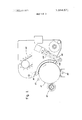
- FIG. 3 is an isometric view of the embodiment illustrated in FIG. 2.
- the machine includes an electrophotographic plate or surface It) formed in the shape of a drum.
- the plate has a photoconductbc or light responsive layer on a condt
- the rotation will cause the plate to sequentially pass a series of electrophotographic processing stations.
- the several electrophotographie processing stations in the path of movement of the plate surface may be described functionally as follows:
- a developing station 40 including the recirculation unit of the present invention. at which clectrophotographic developing material. including toner particles having an electrostatic charge opposite that of the latent electrostatic image is cascaded over the plate surface whereby the toner particles adhere to the latent electrostatic image to fornt a visible toner image in an configuration of the copy being reproduced:
- the leakage developer recirculation unit 101 of the present invention includes a leakage developer catch assembly 102 and a leakage developer return conveyor assembly 130.
- the catch assembly 102 is in the form of a tray H which extends axially along the length of the drum immediately below the space between the developing station 40 and the electrostatographic recording surface of the drum l0.
- the tray H0 is comprised of a bottom wall 11].
- the side wall [12 is provided with an outlet means in the form of an exit port [15 positioned at the front end of the tray 110.
- the bottom wall 111 opposite side wall.
- 112 includes an upwardly angularly extending longitu dinal lip 116 positioned closely adjacent to the surface of the drum 10. with the lip 116 aiding in catching developer which has leaked from the developing station 40.
- the tray lit) is protided with a conveying means in the form of an endless flexible member 121. such as the spring particularly shown. supported around longitudinally spaced drner pulley I22 and idler pulley 123 journaled to the bottom wall [ll of the tray H0.
- the driver pulley 12.! is drivingly connected to a drive means. in the form of motor 124. mounted on a support plate I25 which is mounted to the bottom wall 11] of tray 110.
- the tray is positioned at an angle with respect to horizontal whereby developer retained in the tray 110 is urged toward the side wall 112.
- the tray is removably supported in such a position in a bracket [25. defining a track. which is mounted (not shown) to the frame of the developer housing of the development station 40.
- the forward portion of the tray [10 is not positioned in the bracket 126. whereby developer may freely flow front the tray through the exit port H5.
- a conveyor assembly for returning leaked developer to the developer housing developing station 40 includes a conveyor comprised of an endless belt 13] carrying a plurality of buckets I32 movably mounted in a conveyor housing 133.
- the belt 13] is mounted about an idler roller [34 and a driven roller which is drivingly connected to a suitable drive means. such as motor 136. through a drive belt assembly 137 for driving the conveyor in the direction indicated by the arrow.
- the conveyor housing I33 includes an angularly outwardly upwardly extending lip 138 which is positioned adjacent to and immediately below the outlet port [[5 in tray ill). with the lip I38 functioning as a ramp or chute for transporting developer withdrawn through the port [[5 to a sump 139 formed in the bottom of the conveyor housing [33.
- the top portion of the housing U3 is provided with a collection means for collecting and transporting developer dumped front the buckets I32 to the developer housing of development station 40.
- the collection means includes a shoulder portion 1-H having an angular bore 142 therein which is positioned to receive developer dumped from the buckets 132.
- a tube 143 is connected between the outlet of bore 142 and an inlet port in the developer housing of the development station 40 for transporting developer from the bore 142 to the developer housing of the development station 40.
- developer which leaks between the drum l0 and the housing ofthe development station 40 is caught by tray lit).
- the developer caught in tray 110 is continuously transported by the flexible member 121 to the exit port US.
- the developer falls through the exit port 115 onto the lip 138 of the conveyor housing 133, and from the lip 138 the developer falls into the sump 139.
- the developer is transported from the sump 139 by the buckets X32 and is dumped from the buckets 132, at the roller 135, into the bore [42 in shoulder 14].
- the developer falls through bore 141 into return tube 143 and is transported through return tube 143 into the developer housing of the development station 40.
- the conveying means defined by the spring 121, in tray H0, is self cleaning in that any developer entrapped in the spring is released therefrom by the expansion ofthe spring 121 around pulleys 122 and 123. ln this manner the tray H0 and the conveying means defined by spring 121 is maintained. at all times, essentially free of developer.
- the present invention has been particularly described with respect to an elcctrophotographic reproducing machine using a rotating drum as a recording surface.
- the present invention may also be employed in machines employing other types of recording surfaces: eg. a rotating belt.
- the present invention is particularly applicable to a machine using a cascade development technique.
- the present invention is also suitable for a machine using another development technique in which developer leakage is a problem.
- the present invention is also applicable to electrostatographic processes other than the electrophotographic type.
- electrostatic processes in which an electrostatic latent image is formed by a pulsing electrode.
- the present invention is particularly advantageous in that the developer which leaks from the development station is effectively and facilely recovered. In particular. there is no build-up of leaked developer which results in a cleaner operation. Furthermore. developer which would normly be lost from the system is effectively returned to the system.
- an electrostatographic apparatus containing a development station for developing an electrostatic la tent image formed on a surface including a developer housing in which solid developer is stored. transported to the electrostatic latent image bearing surface and received from said electrostatic latent image bearing surface. the improvement comprising:
- catch means positioned externally to said developer housing for receiving solid developer which leaks past the developer housing during the development of the electrostatic latent image.
- said catch means comprising a tray positioned beneath said developer housing adjacent to the electrostatic latent image bearing surface to receive developer leaks between the electrostatic latent image bearing surface and the developer housing.
- said tray including an outlet port for withdrawing developer therefrom. and a conveying means in said tray for conveying developer within said tray to said outlet port.
- said conveying means comprising a movable endless belt journaled in said tray, and
- an electrographic apparatus containing a cas' cadc development station for developing an electrostaie latent image formed on a surface including a developer housing in which solid developer is stored. transported to the electrostatic latent image bearing surface and received from said electrostatic latent image hearing surface. the improvement comprising:
- catch means positioned externally to said developer housing for receiving solid developer which leaks past the developer housing during the development of the electrostatic latent image.
- said catch means comprising a tray positioned beneath said devel oper housing adjacent to the electrostatic latent image bearing surface to receive developer which leaks between the electrostatic latent image hearing surface and the developer housing.
- said tray including an outlet port for withdrawing developer therefrom. and a conveying means in said tray for conveying developer within said tray to said outlet port.
- catch means positioned externally to said developer housing for receiving solid developer which leaks past the developer housing during the development of the electrostatic latent image.
- said catch means comprising a tray positioned beneath said developer housing adjacent to the electrostatic latent image bearing surface to receive developer which leaks between the electrostatic latent image hearing surface and the developer housing.
- said tray including an outlet port for withdrawing developer therefrom.
- a conveying means in said tray for conveying developer within said tray to said outlet port.
- said conveying means comprising two spaced pulleys journaled in said tray and an endless flexible member supported in said tray around said two pulleys.
- an electrographic apparatus containing a cascade development station for developing an electrostatic latent image formed on a surface including a developer housing in which solid developer is stored. transported to the electrostatic latent image bearing surface and received from said electrostatic latent image bearing surface. the improvement comprising:
- catch means positioned externally to said developer housing for receiving solid developer which leaks past the developer housing during the development of the electrostatic latent image.
- said catch means comprising a tray. including a developer outlet aperture. said tray positioned below said cascade development station. said tray including a conveying means comprising first and second longitudinally spaced pulleys journaled in said tray. an endless flexible member mounted around said pulleys and drive means for driving one of said pulleys. said flexible member conveying developer in said tray to said developer outlet aperture.
- said transport means comprising a conveyor housing including a ramp for receiving developer from said outlet aperture and transporting said developer into said conveyor housing.
- a bucket conveyor journaled in said conveyor housing. means for conveying developer from said conveyor housing to said developer and means for driving said bucket conveyor to convey developer introduced into said conveyor housing to said means for conveying developer from said conveyor housing to said developer housing.
- an electrostatographic apparatus containing a development station for developing an electrostatic latent image formed on a surface including a developer housing in which solid developer is stored. transported to the electrostatic latent image bearing surface and received from said electrostatic latent image bearing sur face. the improvement comprising:
- catch means positioned externally to said developer housing for receiving developer which leaks past the developer housing during the development of the electrostatic latent image.
- said catch means comprising a tray positioned beneath said developer housing adjacent to the electrostatic latent image bearing surface to receive developer which leaks between the electrostatic latent image bearing surface and the developer housing.
- said tray including an outlet port for withdrawing developer therefrom. and a conveying means in said tray for conveying developer within said tray to said outlet port.
- said tray further including a lip portion and a vvall member opposite said lip portion of said tray. said lip portion being positioned adjacent said electrostatic latent image bearing surface.
- said wall member including said outlet port. said tray being supported at an angle with respect to horizontal to image developer toward said ⁇ vall member.
Landscapes
- Physics & Mathematics (AREA)
- General Physics & Mathematics (AREA)
- Dry Development In Electrophotography (AREA)
Priority Applications (2)
| Application Number | Priority Date | Filing Date | Title |
|---|---|---|---|
| US250637A US3884571A (en) | 1972-05-05 | 1972-05-05 | Leakage developer recirculation assembly |
| NL7306223A NL7306223A (enExample) | 1972-05-05 | 1973-05-04 |
Applications Claiming Priority (1)
| Application Number | Priority Date | Filing Date | Title |
|---|---|---|---|
| US250637A US3884571A (en) | 1972-05-05 | 1972-05-05 | Leakage developer recirculation assembly |
Publications (1)
| Publication Number | Publication Date |
|---|---|
| US3884571A true US3884571A (en) | 1975-05-20 |
Family
ID=22948555
Family Applications (1)
| Application Number | Title | Priority Date | Filing Date |
|---|---|---|---|
| US250637A Expired - Lifetime US3884571A (en) | 1972-05-05 | 1972-05-05 | Leakage developer recirculation assembly |
Country Status (2)
| Country | Link |
|---|---|
| US (1) | US3884571A (enExample) |
| NL (1) | NL7306223A (enExample) |
Cited By (1)
| Publication number | Priority date | Publication date | Assignee | Title |
|---|---|---|---|---|
| EP0008040A1 (de) * | 1978-08-04 | 1980-02-20 | Hoechst Aktiengesellschaft | Magnetbürsten-Entwicklungsvorrichtung für elektrostatische Ladungsbilder |
Citations (7)
| Publication number | Priority date | Publication date | Assignee | Title |
|---|---|---|---|---|
| US878003A (en) * | 1906-12-26 | 1908-02-04 | Morris Jacobs | Bolt. |
| US3543720A (en) * | 1968-02-29 | 1970-12-01 | Eastman Kodak Co | Apparatus for development of electrostatic images |
| US3639050A (en) * | 1969-01-22 | 1972-02-01 | Itt | Particle-applicating device |
| US3651782A (en) * | 1969-09-02 | 1972-03-28 | Eastman Kodak Co | Liquid development apparatus |
| US3678896A (en) * | 1971-01-28 | 1972-07-25 | Xerox Corp | Conveyor system |
| US3682538A (en) * | 1970-03-19 | 1972-08-08 | Xerox Corp | Xerographic pick-off plate |
| US3687708A (en) * | 1969-05-21 | 1972-08-29 | Scm Corp | Liquid development of latent electrostatic images |
-
1972
- 1972-05-05 US US250637A patent/US3884571A/en not_active Expired - Lifetime
-
1973
- 1973-05-04 NL NL7306223A patent/NL7306223A/xx unknown
Patent Citations (7)
| Publication number | Priority date | Publication date | Assignee | Title |
|---|---|---|---|---|
| US878003A (en) * | 1906-12-26 | 1908-02-04 | Morris Jacobs | Bolt. |
| US3543720A (en) * | 1968-02-29 | 1970-12-01 | Eastman Kodak Co | Apparatus for development of electrostatic images |
| US3639050A (en) * | 1969-01-22 | 1972-02-01 | Itt | Particle-applicating device |
| US3687708A (en) * | 1969-05-21 | 1972-08-29 | Scm Corp | Liquid development of latent electrostatic images |
| US3651782A (en) * | 1969-09-02 | 1972-03-28 | Eastman Kodak Co | Liquid development apparatus |
| US3682538A (en) * | 1970-03-19 | 1972-08-08 | Xerox Corp | Xerographic pick-off plate |
| US3678896A (en) * | 1971-01-28 | 1972-07-25 | Xerox Corp | Conveyor system |
Cited By (2)
| Publication number | Priority date | Publication date | Assignee | Title |
|---|---|---|---|---|
| EP0008040A1 (de) * | 1978-08-04 | 1980-02-20 | Hoechst Aktiengesellschaft | Magnetbürsten-Entwicklungsvorrichtung für elektrostatische Ladungsbilder |
| US4261289A (en) * | 1978-08-04 | 1981-04-14 | Hoechst Aktiengesellschaft | Magnetic brush device for developing electrostatic charge images |
Also Published As
| Publication number | Publication date |
|---|---|
| NL7306223A (enExample) | 1973-07-25 |
Similar Documents
| Publication | Publication Date | Title |
|---|---|---|
| US3405682A (en) | Xerographic development apparatus with web loading means to remove residual developer | |
| US3929098A (en) | Toner loading for touchdown donor | |
| US4116555A (en) | Background removal apparatus | |
| US3872826A (en) | Development system seal | |
| US4098228A (en) | High speed magnetic brush development system | |
| US3851966A (en) | Reproduction apparatus | |
| US3572289A (en) | Magnetic brush development apparatus | |
| US3707947A (en) | Cross-channel mixer | |
| US4545325A (en) | Developing apparatus | |
| US4370050A (en) | Image transfer type copying apparatus with pre-transfer cleaning of transfer paper | |
| US3834804A (en) | Copying machine with means for mounting carrier bead pickoff roller therein | |
| GB2207621A (en) | Toner recycling unit | |
| US4357097A (en) | Electrostatic recording apparatus having a toner recovering device | |
| US3894513A (en) | Copying machine with bead pickoff roller | |
| US3654901A (en) | Toner reclaiming system | |
| US3635196A (en) | Pneumatically controlled seal | |
| US4088403A (en) | Replenishable photosensitive system | |
| US3884571A (en) | Leakage developer recirculation assembly | |
| US3983841A (en) | Toner reclaim conveyor | |
| US3620191A (en) | Biased input chute | |
| US3984182A (en) | Pretransfer conditioning for electrostatic printing | |
| US3638611A (en) | Electroded development device | |
| US4872036A (en) | Developing apparatus | |
| US5045879A (en) | Image forming apparatus using photosensitive toner | |
| US3872828A (en) | Xerographic copying apparatus with intercepting means for carrier particles |