US3880098A - Metering apparatus for incinerator ash pit - Google Patents
Metering apparatus for incinerator ash pit Download PDFInfo
- Publication number
- US3880098A US3880098A US454368A US45436874A US3880098A US 3880098 A US3880098 A US 3880098A US 454368 A US454368 A US 454368A US 45436874 A US45436874 A US 45436874A US 3880098 A US3880098 A US 3880098A
- Authority
- US
- United States
- Prior art keywords
- chains
- ash pit
- solid materials
- metering
- burnt
- Prior art date
- Legal status (The legal status is an assumption and is not a legal conclusion. Google has not performed a legal analysis and makes no representation as to the accuracy of the status listed.)
- Expired - Lifetime
Links
- 239000011343 solid material Substances 0.000 claims abstract description 121
- 230000007246 mechanism Effects 0.000 claims abstract description 83
- 238000002485 combustion reaction Methods 0.000 claims abstract description 78
- 230000004888 barrier function Effects 0.000 claims abstract description 45
- 238000009825 accumulation Methods 0.000 claims abstract description 39
- 239000002699 waste material Substances 0.000 claims abstract description 31
- 239000000446 fuel Substances 0.000 claims abstract description 21
- 239000000463 material Substances 0.000 claims abstract description 21
- 239000007787 solid Substances 0.000 claims abstract description 18
- 230000005484 gravity Effects 0.000 claims abstract description 14
- 230000006872 improvement Effects 0.000 claims abstract description 13
- 230000035508 accumulation Effects 0.000 claims description 38
- 230000009471 action Effects 0.000 claims description 33
- 238000007665 sagging Methods 0.000 claims description 25
- 238000010276 construction Methods 0.000 claims description 10
- 230000000737 periodic effect Effects 0.000 claims description 10
- 239000002245 particle Substances 0.000 claims description 8
- 230000000977 initiatory effect Effects 0.000 claims description 5
- 230000003213 activating effect Effects 0.000 claims description 2
- 230000002411 adverse Effects 0.000 description 3
- 239000003795 chemical substances by application Substances 0.000 description 1
- 230000003247 decreasing effect Effects 0.000 description 1
- 230000001419 dependent effect Effects 0.000 description 1
- 230000007613 environmental effect Effects 0.000 description 1
- 230000001788 irregular Effects 0.000 description 1
- 230000004044 response Effects 0.000 description 1
- 230000000630 rising effect Effects 0.000 description 1
- 235000008790 seltzer Nutrition 0.000 description 1
Images
Classifications
-
- F—MECHANICAL ENGINEERING; LIGHTING; HEATING; WEAPONS; BLASTING
- F23—COMBUSTION APPARATUS; COMBUSTION PROCESSES
- F23J—REMOVAL OR TREATMENT OF COMBUSTION PRODUCTS OR COMBUSTION RESIDUES; FLUES
- F23J1/00—Removing ash, clinker, or slag from combustion chambers
Definitions
- ABSTRACT The improvement, in an incinerator controlled air type includedin METERING APPARATUS FOR INCINERATOR ASH PIT preferably of the g a combustion chamber [75] Inventor: Robert Elmer McRee. Jr., Charlotte.
- This invention relates to the improvement, in an incinerator preferably of the controlled air type, of means positioned in the ash pit of the incinerator for receiving burnt solid materials, for causing bridging and accumulation of the burnt solid materials thereon and upwardly therefrom for providing an air barrier within the ash pit and for selective actuation for selective metering of the burnt solid materials therethrough and to the bottom of the ash pit for reception and removal by a conveyor mechanism to prevent clogging and jamming of the conveyor mechanism.
- an incinerator preferably of the controlled air type, which includes a combustion chamber for burning of waste material or fuel, an ash pit extending generally vertically downwardly from the combustion chamber for receiving therefrom and passing therethrough to the bottom thereof by gravity flow burnt solid materials which may include irregularshaped solids and which have natural bridging characteristics, and a conveyor mechanism communicating with generally the bottom of the ash pit for successively removing the burnt solid materials therefrom.
- the mechanisms of this invention include means positioned generally medially of the ash pit for receiving the burnt solid materials as they pass downwardly through the ash pit from the combustion chamber and for successively metering the burnt solid materials to the conveyor mechanism for successive removal from the ash pit to prevent clogging and jamming of the conveyor mechanism.
- the aforesaid means also causes bridging and accumulation of the burnt solid materials upwardly therefrom through the ash pit for providing an air barrier within the ash pit to prevent the passage of undesirable air into the controlled environment combustion chamber and a heat barrier against the heat within the combustion chamber to prevent damage to the mechanism in the ash pit.
- the aforesaid means preferably comprises a first set of generally horizontally-disposed, sagging, flexible, spaced-apart chains extending across the ash pit and being fixedly secured at the ends thereof to the sides of the ash pit above the conveyor mechanism, a second set of generally horizontally-disposed, sagging, flexible, spaced-apart chains extending across the ash pit slightly above the first set of chains.
- the first and second sets of chains are so positioned for causing the bridging and accumulation of the burnt solid materials thereon and upwardly through the ash pit.
- Means are provided for carrying and selectively reciprocating the second set of chains with respect to the first set of chains for breaking the bridging of the burnt solid materials in contact with the sets of chains for causing the burnt solid materials which may include irregularshaped particles to successively work their way through and move between the chains of the first and second sets by moving individual chains away from each other and toward each other through the sagging and flexible construction thereof during the reciprocating action of the second set of chains and thereby successively meter the burnt solid materials to the bottom of the ash pit for reception and successive removal by the conveyor mechanaism.
- the incinerator includes a charging means for charging the combustion chamber with waste material or fuel and the means for actuating the reciprocating means of the second set of chains is operatively connected with and activated by the charging means for initiating a timed cycle of operation of the reciprocating means.
- a temperature sensor positioned in the ash pit for deactivating the actuating means and stopping the timed metering action of the metering means in the event the temperature in the ash pit exceeds a predetermined level which indicates that the accumulation of burnt solid materials above the bridging and metering means has reduced to a point where the air barrier provided thereby may be broken.
- the improvements of this invention are equally useful in a furnace or waste burning incinerator and the term incinerator as used herein is considered to be generic to both a furnace and an incinerator.
- the metering and accumulation means of this invention is adaptable for use in any material handling apparatus which includes an enclosed vertically extending passageway for the passage by gravity flow of solid materials and such a passageway would be in the form of the ash pit of the incinerator specifically described herein.
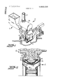
- FIG. I is a perspective, schematic view of an incinerator of the type having main and secondary combustion chambers, ram-type charging mechanism and ash removal system which includes the improvements of the present invention therein;
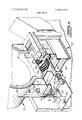
- FIG. 2 is an enlarged, partial, elevational, sectional view taken through the ash pit from the left side of FIG. 1'.
- FIG. 3 is an enlarged, partial, perspective view, broken away and partly in section looking down through the ash pit from the left side of the incinerator of FIG. 1;
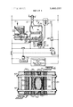
- FIG. 4 is a partial, elevational, sectional view through the ash pit of the incinerator of FIG. 1 and looking generally at the front of the incinerator as viewed in FIG.
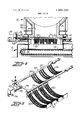
- FIG. 5 is an enlarged, perspective, exploded view, broken away, of the first and second sets of chains forming the metering and bridging mechanisms of this invention
- FIG. 6 is a schematic, diagrammatic view of the apparatus shown in FIG. 1 with the control system therefor;
- FIG. 7 is a partial, sectional, top plan view looking down on the metering and accumulating means of this invention through the ash pit of the incinerator of FIG. I, and illustrating an irregular shaped solid passing thercthrough during reciprocation thereof.
- This incinerator 10 is provided with an automatic charging or feed means, 5 generally indicated by the reference numeral 11, of the double ram type as disclosed in U.S. Pat. No. 3,708,078, issued Jan. 2, 1973, and assigned to the assignee of the present invention. Also, the incinerator 10 is provided with an ash removal system, generally indicated by the reference numeral I2, of the general type disclosed in U.S. Pat. application Ser. No. 378,657, filed July l2, I973, and assigned to the assignee of the present invention.
- the apparatus of the present invention may be used in connection with other types of incinerators which may be provided with different types of mechanisms for manually or automatically charging or feeding the waste material or fuel into the incinerator to be burned and other types of ash removal systems.
- the controlled emission incinerator I includes a controlled environment main combustion chamber 15 for receiving waste material or fuel from the charging mechanism 11 and for burning the waste material therein.
- the main combustion chamber I communicates with a secondary combustion chamber 16 for secondary burning of the products of incomplete combustion from the main combustion chamber 15 and which includes an exhaust stack I7.
- This duel chamber incinerator for the burning of waste materials is well understood by those with ordinary skill in the art and further details of the operation thereof may be obtained by reference to the assignees aforementioned U.S. Patent.
- the incinerator 10 is charrged with waste material or fuel by the charging apparatus 11 which, as illustrated herein, comprises a double chamber, double ram mechanism including (see FIG. 6) a hopper 20 into which waste material or fuel is deposited and which communicates with a first compartment 21.
- the first compartment 21 receives the waste material from the hopper 20 when the ram 22 therein is in a rearward position and the waste material is pushed forwardly in the compartment 21 by the ram 22 to allow the waste material to drop down into a second compartment 23 when the ram 24 therein is in its rearward position.
- the ram 24 then pushes the waste material forwardly into the main combustion chamber for charging of the combustion chamber 15.
- the burnt solid materials or ash in the main combustion chamber 15 of the incinerator 10 are pushed forwardly of the incinerator l0 and over a vertically extending ash pit 25 forming part of the ash removal system I2.
- the burnt materials will pass vertically downwardly through the ash pit 25 by gravitty flow for reception and successive removal thereof by a conveyor mechanism 30.
- the arm removal conveyor mechanism may be generally of the type set forth in assignees U.S. Patent application Ser. No. 378,657 and, as illustrated herein, differs from the conveyor mechanism of that patent application by being generally in the form of an endless apron conveyor 30 passing around driven sprockets 32 on each end thereof to communicate with the bottom of the ash pit 25 for reception and successive removal of the burnt solid materials received in the ash pit 25 from the main combustion chamber 15 of the incinerator 10.
- the apron conveyor 30 and the sprockets 32 are driven by any suitable motor or other drive mechanisms (not shown). Further details of the operation of an ash removal conveyor mechanism may be had by reference to assignees aforementioned United States Patent application.
- the above described apparatus is provided with means positioned generally medially of the ash pit 25 of the ash removal system 12 for receiving burnt solid materials as they pass downwardly through the ash pit 25 from the main combustion chamber 15 of the incinerator by gravity flow and utilizing the natural bridging characteristics of such burnt solid materials for causing bridging and accumulation of the burnt solid materials upwardly therefrom through the ashpit 25 (see FIG.
- This bridging and metering means comprises a first set of generally horizontally-disposed, sagging, flexible, spaced-apart chains 50 extending across the ash pit 25 and being fixedly secured at each end thereof to the sides of the ash pit 25 above the conveyor mechanism 30. As may be seen in FIGS. 2 and 3, the chains 50 of the first set extend through a slot on each sic of the ash pit 25 and are secured to end plates 51 which are mounted on the outside walls of the ash pit 25.
- the bridging and metering means further comprises a second set of generally horizontally-disposed, sagging, flexible, spaced-apart chains 55 extending across the ash pit slightly above the first set of chains 50.
- the first and second sets of chains 50, 55 are so positioned for causing the bridging and accumulation of the burnt solid materials thereon and upwardly through the ash pit, as shown in FIG. 2, for providing the abovediscussed air barrier and heat barrier.
- Means are provided for carrying and selectively reciprocating the second set of chains 55 with respect to the first set of chains 50 for breaking the bridging of the burnt solid materials in contact with the sets of chains 50, 55 for causing the burnt solid materials which may include irregular-shaped particles to successively work their way through and move between the chains of the first and second set by moving individual chains away from each other and toward each other through the sagging and flexible construction of the chains during the reciprocating action of the second set of chains 55 and thereby successively meter the burnt solid materials to the bottom of the ash pit 25 for reception and successive removal by the conveyor mechanism 30.
- This means for carrying a.. electively reciprocating the second set of chains 55 comprises a pair of spacedapart, elongate, generally parallel shafts 57 extending through apertures in opposed walls of the ash pit 25 (see FIGS. 3 and 4) for back and forth reciprocating linear movement.
- the shafts 57 opposite ends of the chains 55 secured thereto, respectively. for movement therewith.
- a driven mechanical linkage 58 which is pivotally secured to a cross shaft 59 extending transversely between and connecting the pair of shafts 57.
- the mechanical linkage 58 is connected with a gear mechanism 56 which is selectively driven by a selectively operated motor 60.
- the gear mechanisms 56 may be any type of linear actuator which converts rotary motion of the motor 60 into linear motion of the mechanical linkage 58. Suitable linear actuator mechanisms include ball screw mechanisms, etc., all of which are well known to those with ordinary skill in the art and specific details thereof is not deemed necessary herein.
- the ash pit 25 For aiding in the bridging action and metering action of the burnt solid materials by the first and second sets of chains 50, 55 the ash pit 25, as shown particularly in FIG. 2, comprises a section extending above the sets of chains 50, 55 of less cross-sectional dimensions than the lengths of these chains 50, 55, which aids in the bridging action of the burnt solid materials thereon.
- the ash pit 25 further includes a section below the sets of chains 50, 55 of greater cross-sectional dimensions than the upper section and greater than the second set of reciprocating chains 55 for aiding in the metering action through the sets of chains 50, 55 by providing a passageway larger than the passageway above the sets of chains in the ash pit 25.
- the chains 50, 55 of the first and second sets are positioned in groups of chains (see FIGS. 4, 5 and 7) in which each chain of each group is slightly spaced-apart from each other and in which each group is spaced a greater distance apart from adjacent groups.
- the groups of chains of the first and second sets 50, 55 are generally staggered with respect to each other so that the chains of the groups in one of the sets generally covers the spacing between the chains of the groups of the other of the sets when the second set of chains 55 is stationary and not reciprocating. This may be clearly seen in FIG. 4 in which the second set of chains 55 is shown in a stationary position. Also, reference may be had to FIG.
- This means for selectively actuating the reciprocating means is preferably operatively connected with and activated by the charging mechanaism ll of the incinerator 10 for initiating a timed cycle of operation of the reciprocating means.
- a temperature sensor 65 positioned in the ash pit 25 for deactivating the actuating means and stopping the timed metering action of the sets of chains 50, 55 in the event that temperature in the ash pit 25 exceeds a predetermined level which indicates that the accumulation of burnt solid materials above the sets of chains 50, 55 has reduced to a point where the desired air barrier and heat barrier provided thereby may be broken.
- an electrical circuit is provided which is connected between the incinerator charging means 11, the motor controls for the ash removal system which includes the motor 60 for reciprocating the first and second sets of chains 50, 55 of the bridging and metering means and may include the motor (not shown) for driving the conveyor removal mechanism 30, and the temperature sensor mechanism 65.
- This circuit includes a normally open switch 67 which is operatively connected with the charging mechanism 11 and is closed by forward movement of the lower ram 24 during a charging operation of waste material or fuel into the main combustion chamber 15. While this switch 67 has been illustrated as being operated by the lower ram of a double ram charging mechanism, as described in the assignees aforementioned United States Patent, it is to be understood that this switch 67 could be operted by any charging mechanism including a single ram mechanism or by the opening of a door to the main combustion chamber for manual charging thereof.
- the timer switch 70 When the timer switch 70 is closed, the circuit to the motor controls will be completed even though the switch 67 is opened by the rearward movement of the ram mechanism 24 or the closing ofa door to the main combustion chamber of the incinerator 10.
- the timer switch 70 may be set for a predetermined time period and upon expiration of this time period, this normally open switch 70 will again open to break the circuit to solenoid operated switch 69 to allow this normally open switch to again open and thereby break the circuit to the motor controls and stop operation of the motor 60 and thus the reciprocating action of the second set of chains 55.
- the temperature sensor 65 which may be a thermocouple type sensor, is connected with an adjustable control switch 72 for being closed by the temperature sensor 65 upon the temperature in the ash pit rising above a predetermined setting on the adjustable switch 72.
- the adjustable switch 72 is closed by the temperature sensing thermocouple 65, a circuit will be completed to the normally closed solenoid operated switch 68 for opening the switch 68 and thus breaking the circuit to the solenoid operated switch 69 for allowing this normally open switch 69 to open and thereby break the circuit to the motor controls for the reciprocating mechanism of the second set of chains 55 regardless of whether the timed switch 70 has timed out or not.
- a control circuit is provided for operating the reciprocating mechanisms of the second set of chains 55, which is activated by the charging mechanism 11 or any charging action into the incinerator 10 for a predetermined timed cycle of operation for metering of burnt solid materials through the ash pit 25 and onto the conveyor mechanism 30 for successive removal thereof by the conveyor mechanism 30.
- This circuit is provided with a temperature sensor 65 positioned within the ash pit for sensing a rise in temperature in the ash pit above a predetermined temperature, which indicates that the accumulation of burnt solid materials above the sets of chains 50, 55 has decreased to a point in which the desired air barrier and heat barrier provided thereby may be broken, for breaking the circuit to the motor 60 and thereby stopping operation of the reciprocating linkages for the second set of chains 55 and thus stop the metering action of the burnt solid mterials therethrough and allow the accu mulation of the burnt solid materials to again build up on top of the chains 50, 55 to the desired level for providing the air barrier and heat barrier.
- the accumulation and metering apparatus of this invention further includes means for supplying under fire air up through the ash pit and into the main combustion chamber 15 of the incinerator 10 for aiding in combustion of the waste material therein.
- the shafts 57 comprise hollow shafts and include a plurality of generally upwardly directed air nozzles extending outwardly therefrom for allowing the flow of air from the interior of the hollow shafts 57 upwardly in the direction of the arrows in FIG. 2 through the accumulated burnt solid materials in the upper portion of the ash pit 25 and into the main combustion chamber 15 for supplying under fire air thereto.
- the shaft 59 is also of a hollow construction for communicating with the interior of the hollow shafts 57.
- a flexible air conduit 76 communicates at one end with the interior of the hollow shaft 59 and includes a manual air valve 77 thereon. The other end of the flexible conduit 76 is connected with the side wall 78 of an air plenum or chamber 79 which receives pressurized air from a conduit 80 connected with the normal incinerator air flow mechanisms, as shown in FIG. 1, for the supplying of air under pressure thereto.
- air under pressure is supplied to the interior of the hollow reciprocating shafts S7 for passage out of the nozzles 75 for supplying under fire air to the main combustion chamber of the incinerator 10.
- This means is controlled by the charging apparatus of the incinerator for initiating a timed cycle of metering action which may be interrupted by a temperature sensor within the ash pit when the level of the accumulation of burnt solid materials has dropped to such a point that the desirable air barrier and heat barrier provided thereby may be broken.
- the metering and accumulation means is adaptable for use in any incinerator, furnace, etc. and for use in any material handling apparatus having a vertically extending passageway for the passage of solid materials therethrough which may include irregular-shaped solids.
- an incinerator including a combustion chamber for burning waste material or fuel, an ash pit extending vertically downwardly from the combustion chamber for the reception and passage therethrough by gravity flow of burnt solid materials which may include irregular-shaped solids, and a conveyor mechanism for communicating generally with the bottom of the ash pit for successively removing the burnt materials from the ash pit; the improvement therewith of means positioned generally medially of the ash pit for receiving the burnt solid materials from the combustion chamber and for successively metering the burnt materials to the conveyor mechanism for successive removal from the ash pit to prevent clogging and jamming of the conveyor mechanism, said means comprising:
- a first set of generally horizontally-disposed, sagging, flexible, spaced-apart chains extending across the ash pit and being fixedly secured at the ends thereof to the sides of the ash pit above the conveyor mechanism;
- said chains of said first and second sets are positioned in groups of chains in which each chain of each group is slightly spaced apart from each other and in which each group is spaced a greater distance apart from adjacent groups, and in which said groups of said first and second sets are generally staggered with respect to each other so that the chains of said groups in one of said sets generally covers the spacing between said chains of said groups of the other of said sets when said second set is stationary and not reciprocating.
- a controlled air incinerator including a combustion chamber having a controlled combustion environment therein for burning waste material or fuel, an ash pit extending generally vertically downwardly from the combustion chamber for receiving therefrom and passing therethrough to the bottom thereof by gravity flow burnt solid materials which may include irregularshaped solids and which have natural bridging characteristics, and a conveyor mechanism communicating with generally the bottom of the ash pit for successively removing the burnt solid materials therefrom;
- the ash pit comprising a section extending above said bridging and metering means of less cross-sectional dimensions than the length of said bridging and metering means for aiding in the briding action of the burnt solid materials thereon and a section below said metering means of greater cross-sectional dimensions than said bridging and metering means for aiding in the metering thereof.
- said bridging and metering means comprises a first set of generally horizontally-disposed, sagging, flexible, spaced-apart chains extending across the ash pit and being fixedly secured at the ends thereof to the sides of the ash pit above the conveyor mechanism,
- a second set of generally horizontally-disposed, sag ging, flexible, spaced-apart chains extending across the ash pit slightly above said first set of chains, said first and second sets of chains being so positioned for causing the bridging and accumulation of the burnt solid materials thereon and upwardly through the ash pit,
- said chains of said first and second sets are positioned in groups of chains in which each chain of each group is slightly spaced apart from each other and in which each group is spaced a greater distance apart from adjacent groups, and in which said groups of said first and second sets are generally staggered with respect to each other so that the chains of said groups in one of said sets generally covers the spacing between said chains of said groups of the other of said sets when said second set is stationary and not reciprocating.
- a controlled air incinerator including a combustion chamber having a controlled combustion environment therein for burning waste material or fuel, charging means for charging the combustion chamber with waste material or fuel, an ash pit extending generally vertically downwardly from the combustion chamber for receiving therefrom and passing therethrough to the bottom thereof by gravity flow burnt solid materials which may include irregular-shaped solids and which have natural bridging characteristics, and a conveyor mechanism communicating with generally the bottom of the ash pit for successively removing the burnt solid materials therefrom;
- said means for actuating said metering means for timed, periodic metering action of said metering means includes a temperature sensor positioned in the ash pit for deactivating said actuating means and stopping the timed metering action of said metering means in the event the temperature in said ash pit exceeds a predetermined level which indicates that the accumulation of burnt solid materials above said bridging and metering means has reduced to a point where the air barrier and heat barrier provided thereby may be broken.
- incinerator includes a charging means for charging the combustion chamber with waste material or fuel
- said means for selectively actuating said reciprocating means of said second set of chains comprises electrical circuit means connected with said reciprocating means of said second set of chains for actuating and deactuating operation thereof
- switch means operatively associated with said combustion chamber charging means for being actuated thereby during a charging operation of the combustion chamber for activating said electrical circuit means and actuating said reciprocating means for said second set of chains,
- timing means connected in said electrical circuit means for maintaining said electrical circuit means activated for a predetermined period of time after actuation thereof by said charging means switch means and for deactivating said electrical circuit after a predetermined time period to deactuate operation of said reciprocating means for said second set of chains to stop operation of said metering means, and
- thermosensor means positioned in the ash pit and connected with said electrical circuit means for deactivating said electrical circuit means after actuation thereof by said charging means switch means in the event the temperature in the ash pit exceeds a predetermined level and indicates that the accumulation of burnt materials on and above said bridging and metering means has reduced to a point in which the air barrier and heat barrier provided thereby may be broken.
- a controlled air incinerator as set forth in claim 8, further including adjustable control switch means connected with said sensing means in said electrical circuit means for selectively varying the predetermined temperature level of operation of said temperature sensing means.
- said means for carrying and selectively reciprocating said second set of chains comprises a pair of spaced-apart, elongate, generally parallel shafts extending through apertures in opposed walls of the ash pit for back and forth reciprocating linear movement and having opposite ends of said chains of said second set secured thereto for movement therewith,
- said pair of shafts comprise hollow shafts having a plurality of spaced-apart, generally upwardly directed air nozzle means extending therefrom, and in which a compressed air supply conduit is connected with said shaft for supplying compressed air to the interior of said hollow shafts for passage out of saidi nozzle to supply under fire air up through the ash pit and into the combustion chamber of the incinerator.
- a material handling apparatus having a generally vertically extending, enclosed passageway for the passage by gravity flow of solid materials which may include irregular-shaped solids and which have natural briding characteristics; the improvement of means positioned generally medially of the passageway for receiving the solid materials as they pass downwardly through the passageway for causing bridging and accumulation of the solid materials thereon and upwardly therefrom through the passageway and for selective actuation for successive .metering of the solid materials therethrough to the bottom of the passageway, said means comprising:
- a first set of generally horizontally-disposed, sagging, flexible, spaced-apart chains extending across the passageway and being fixedly secured at the ends thereof to the sides of the passageway;
- said means for carrying and selectively reciprocating said second set of chains comprises a pair of spaced-apart, elongate, generally parallel shafts extending through apertures in opposed walls of the passageway for back and forth reciprocating linear movement and having opposite ends of said chains of said second set secured thereto for movement therewith,
- said chains of said first and second sets are positioned in groups of chains in which each chain of each group is slightly spaced apart from each other and in which each group is spaced a greater distance apart from adjacent groups, and in which said groups of said first and second sets are generally staggered with respect to each other so that the chains of said groups in one of said sets generally covers the spacing between said chains of said groups of the other of said sets when said second set is stationary and not reciprocating.
Landscapes
- Engineering & Computer Science (AREA)
- Mechanical Engineering (AREA)
- General Engineering & Computer Science (AREA)
- Incineration Of Waste (AREA)
Abstract
The improvement, in an incinerator preferably of the controlled air type including a combustion chamber for burning waste material or fuel, as ash pit for receiving burnt solid materials which may include irregular-shaped solids and a conveyor mechanism for successively removing the burnt materials from the ash pit, as follows. Apparatus, positioned generally medially of the ash pit which extends generally vertically for receiving the burnt solid materials as they pass downwardly through the ash pit by gravity flow from the combustion chamber, for causing bridging and accumulation of the burnt solid materials upwardly therefrom through ash pit for providing an air barrier within the ash pit to prevent the passage of undesirable air into the controlled environment combustion chamber, and for selective actuation for selective metering of the burnt solid materials therethrough and to the bottom of the ash pit for reception by the removal conveyor mechanism to prevent clogging and jamming of the conveyor mechanism.
Description
United States Patent 11 1 McRee, Jr.
[ Apr. 29, 1975 [57] ABSTRACT The improvement, in an incinerator controlled air type includin METERING APPARATUS FOR INCINERATOR ASH PIT preferably of the g a combustion chamber [75] Inventor: Robert Elmer McRee. Jr., Charlotte.
for burning waste material or fuel, as ash pit for re- [73] Assignee: Environmental Control Products,
Inc., Charlotte, N.C.
Mar. 25
yor mechanism for ely removing the burnt materials from the as follows. Apparatus, positioned generally medially of the ash pit which extends [22] Filed:
generally verti aterials as Appl. No.: 454.368
cally for receiving the burnt solid m they pass downwardly through the ash pit by gravity flow from the combustion chamber, for causing bridging and accumulati [52] US. 110/8 R; 110/165 R [51] Int. F23g 5/00 on of the burnt solid materials uptherefrom through ash pit for providing an air within the ash pit to prevent the passage of unle air into the controlled environment combustion chamber, and for selective actuation for selective metering of the burnt solid materials therethro to the bottom of the ash pit for rece wardly barrier [58] Field of Search....... 110/7 R, 8 R
desirab ATENTS ugh and n u 6 oe n Y2. be: H o u D.
moval conveyor mechanism to prevent clo jamming of the conveyor mechanism.
RRRRR 5.5558 6666M [/1 OWOO m m ml n m MIN mau C k.k mewmn.. oofi CBPDD 57 81 23.56. 99999 HUM 67.7 0769 63263 30869 205 4 5 .5 a -n -B] 14 Claims. 7 Drawing Figures Primary E.\'uminerKenneth W. Sprague Parrott, Bell, Seltzer. Park Attorney, Agent, or Firm- 8L Gibson METERING APPARATUS FOR INCINERATOR ASl-I PIT BACKGROUND OF THE INVENTION This invention relates to the improvement, in an incinerator preferably of the controlled air type, of means positioned in the ash pit of the incinerator for receiving burnt solid materials, for causing bridging and accumulation of the burnt solid materials thereon and upwardly therefrom for providing an air barrier within the ash pit and for selective actuation for selective metering of the burnt solid materials therethrough and to the bottom of the ash pit for reception and removal by a conveyor mechanism to prevent clogging and jamming of the conveyor mechanism.
Heretofore, various types of systems have been proposed for the removal of ash or burnt solid materials from the ash pit of an incinerator or furnace which burns waste material or fuel. However, these prior systems have either operated on a continuous basis or on an automatic time cycle. In either case, it is difficult to properly adjust the ash removal system to the proper burning cycle so that the ash or burnt solid materials is removed at the proper rate. If too great an amount of burnt solid materials is permitted to accumulate, it will adversely affect the burning of the waste materials or fuel. If too small an amount of ash is accumulated in the ash pit, the heat from the combustion chamber can adversely affect the ash removal mechanisms.
The above problems were overcome by the assignee of the present invention in their co-pending United States Patent Application, Ser. No. 378,657, filed July l2, l973, now U.S. Pat. No. 3,841,241, for Ash Removal System For Incinerator, which provided an ash removal system operative in response to the feeding of waste material to be burned and which maintains the proper amount of ash in the ash pit.
However, certain problems were found to be present in the ash removal system of assignees prior copending patent application, particularly with respect to the removal of burnt solid materials, which may include irregular-shaped solids therein. These problems included jamming or clogging of the ash removal system by the accumulation of these burnt solid materials which may include irregular-shaped solids. Also, certain problems were presented with respect to maintaining an ade quate accumulation of burnt materials within the ash pit to prevent outside air from passing through the ash pit and into the combustion chamber of the incinerator which adversely affects the burning of the waste materials in the incinerator, particularly in a controlled air incinerator.
SUMMARY OF INVENTION Accordingly, it is the object of this invention to overcome the above problems and to provide means for successively metering burnt solid materials to the ash removal mechanisms within the ash pit to prevent clogging and jamming of such mechanisms.
It is a further more specific object of this invention to also provide means for causing bridging and accumulation of the burnt solid materials upwardly therefrom through the ash pit for providing an air barrier within the ash pit to prevent the passage of undesirable air into the controlled environment of the combustion chamber of the incinerator and to provide a heat bar rier against damage of the mechanisms in the ash pit by the heat within the combustion chamber.
It is a further object of this invention to provide a metering mechanism which also functions to cause bridging and accumulation of solid materials having bridging characteristics for use in any material handling apparatus having a vertically extending passageway for the passage therethrough by gravity flow of solid materials which may include irregular-shaped solids.
It has been found by this invention that the above objects may be accomplished by providing the following mechanisms in an incinerator, preferably of the controlled air type, which includes a combustion chamber for burning of waste material or fuel, an ash pit extending generally vertically downwardly from the combustion chamber for receiving therefrom and passing therethrough to the bottom thereof by gravity flow burnt solid materials which may include irregularshaped solids and which have natural bridging characteristics, and a conveyor mechanism communicating with generally the bottom of the ash pit for successively removing the burnt solid materials therefrom. The mechanisms of this invention include means positioned generally medially of the ash pit for receiving the burnt solid materials as they pass downwardly through the ash pit from the combustion chamber and for successively metering the burnt solid materials to the conveyor mechanism for successive removal from the ash pit to prevent clogging and jamming of the conveyor mechanism.
Preferably, the aforesaid means also causes bridging and accumulation of the burnt solid materials upwardly therefrom through the ash pit for providing an air barrier within the ash pit to prevent the passage of undesirable air into the controlled environment combustion chamber and a heat barrier against the heat within the combustion chamber to prevent damage to the mechanism in the ash pit.
The aforesaid means preferably comprises a first set of generally horizontally-disposed, sagging, flexible, spaced-apart chains extending across the ash pit and being fixedly secured at the ends thereof to the sides of the ash pit above the conveyor mechanism, a second set of generally horizontally-disposed, sagging, flexible, spaced-apart chains extending across the ash pit slightly above the first set of chains. The first and second sets of chains are so positioned for causing the bridging and accumulation of the burnt solid materials thereon and upwardly through the ash pit. Means are provided for carrying and selectively reciprocating the second set of chains with respect to the first set of chains for breaking the bridging of the burnt solid materials in contact with the sets of chains for causing the burnt solid materials which may include irregularshaped particles to successively work their way through and move between the chains of the first and second sets by moving individual chains away from each other and toward each other through the sagging and flexible construction thereof during the reciprocating action of the second set of chains and thereby successively meter the burnt solid materials to the bottom of the ash pit for reception and successive removal by the conveyor mechanaism.
Preferably, means are provided for selectively actuating the reciprocating means for timed, periodic metering action of the metering means for removal of the burnt solid materials while maintaining an accumulation of burnt solid materials above the bridging and metering means to provide the air barrier and heat barrier. In the preferred embodment of this invention, the incinerator includes a charging means for charging the combustion chamber with waste material or fuel and the means for actuating the reciprocating means of the second set of chains is operatively connected with and activated by the charging means for initiating a timed cycle of operation of the reciprocating means. Also, it is preferred to provide a temperature sensor positioned in the ash pit for deactivating the actuating means and stopping the timed metering action of the metering means in the event the temperature in the ash pit exceeds a predetermined level which indicates that the accumulation of burnt solid materials above the bridging and metering means has reduced to a point where the air barrier provided thereby may be broken.
The improvements of this invention are equally useful in a furnace or waste burning incinerator and the term incinerator as used herein is considered to be generic to both a furnace and an incinerator. Also, the metering and accumulation means of this invention is adaptable for use in any material handling apparatus which includes an enclosed vertically extending passageway for the passage by gravity flow of solid materials and such a passageway would be in the form of the ash pit of the incinerator specifically described herein.
BRIEF DESCRIPTION OF THE DRAWINGS Some of the objects and advantages of this invention having been stated, other objects and advantages will appear as the description proceeds, when taken in conjunction with the accompanying drawings, in which:
FIG. I is a perspective, schematic view of an incinerator of the type having main and secondary combustion chambers, ram-type charging mechanism and ash removal system which includes the improvements of the present invention therein;
FIG. 2 is an enlarged, partial, elevational, sectional view taken through the ash pit from the left side of FIG. 1'.
FIG. 3 is an enlarged, partial, perspective view, broken away and partly in section looking down through the ash pit from the left side of the incinerator of FIG. 1;
FIG. 4 is a partial, elevational, sectional view through the ash pit of the incinerator of FIG. 1 and looking generally at the front of the incinerator as viewed in FIG.
FIG. 5 is an enlarged, perspective, exploded view, broken away, of the first and second sets of chains forming the metering and bridging mechanisms of this invention;
FIG. 6 is a schematic, diagrammatic view of the apparatus shown in FIG. 1 with the control system therefor; and
FIG. 7 is a partial, sectional, top plan view looking down on the metering and accumulating means of this invention through the ash pit of the incinerator of FIG. I, and illustrating an irregular shaped solid passing thercthrough during reciprocation thereof.
DESCRIPTION OF PREFERRED EMBODIMENT Referring now to the drawings, the apparatus of the present invention is illustrated therein and will be described hereinafter in operation with a controlled emission incinerator, generally indicated by the reference numeral 10, of the type disclosed in U.S. Pat. No.
3,543,700, issued Dec. 1, 1970, and assigned to the assignee of the present invention. This incinerator 10 is provided with an automatic charging or feed means, 5 generally indicated by the reference numeral 11, of the double ram type as disclosed in U.S. Pat. No. 3,708,078, issued Jan. 2, 1973, and assigned to the assignee of the present invention. Also, the incinerator 10 is provided with an ash removal system, generally indicated by the reference numeral I2, of the general type disclosed in U.S. Pat. application Ser. No. 378,657, filed July l2, I973, and assigned to the assignee of the present invention. However, it is to be understood that the apparatus of the present invention may be used in connection with other types of incinerators which may be provided with different types of mechanisms for manually or automatically charging or feeding the waste material or fuel into the incinerator to be burned and other types of ash removal systems.
As may be seen particularly in FIGS. I and 6, the controlled emission incinerator I includes a controlled environment main combustion chamber 15 for receiving waste material or fuel from the charging mechanism 11 and for burning the waste material therein. The main combustion chamber I communicates with a secondary combustion chamber 16 for secondary burning of the products of incomplete combustion from the main combustion chamber 15 and which includes an exhaust stack I7. The operation of this duel chamber incinerator for the burning of waste materials is well understood by those with ordinary skill in the art and further details of the operation thereof may be obtained by reference to the assignees aforementioned U.S. Patent.
The incinerator 10 is charrged with waste material or fuel by the charging apparatus 11 which, as illustrated herein, comprises a double chamber, double ram mechanism including (see FIG. 6) a hopper 20 into which waste material or fuel is deposited and which communicates with a first compartment 21. The first compartment 21 receives the waste material from the hopper 20 when the ram 22 therein is in a rearward position and the waste material is pushed forwardly in the compartment 21 by the ram 22 to allow the waste material to drop down into a second compartment 23 when the ram 24 therein is in its rearward position. The ram 24 then pushes the waste material forwardly into the main combustion chamber for charging of the combustion chamber 15. During this forward motion of the ram 24, the burnt solid materials or ash in the main combustion chamber 15 of the incinerator 10 are pushed forwardly of the incinerator l0 and over a vertically extending ash pit 25 forming part of the ash removal system I2. The burnt materials will pass vertically downwardly through the ash pit 25 by gravitty flow for reception and successive removal thereof by a conveyor mechanism 30.
The arm removal conveyor mechanism, as mentioned above, may be generally of the type set forth in assignees U.S. Patent application Ser. No. 378,657 and, as illustrated herein, differs from the conveyor mechanism of that patent application by being generally in the form of an endless apron conveyor 30 passing around driven sprockets 32 on each end thereof to communicate with the bottom of the ash pit 25 for reception and successive removal of the burnt solid materials received in the ash pit 25 from the main combustion chamber 15 of the incinerator 10. The apron conveyor 30 and the sprockets 32 are driven by any suitable motor or other drive mechanisms (not shown). Further details of the operation of an ash removal conveyor mechanism may be had by reference to assignees aforementioned United States Patent application.
In accordance with this invention, the above described apparatus is provided with means positioned generally medially of the ash pit 25 of the ash removal system 12 for receiving burnt solid materials as they pass downwardly through the ash pit 25 from the main combustion chamber 15 of the incinerator by gravity flow and utilizing the natural bridging characteristics of such burnt solid materials for causing bridging and accumulation of the burnt solid materials upwardly therefrom through the ashpit 25 (see FIG. 2) for providing an air barrier within the ash pit 25 to prevent the passage of undesirable air from outside into the controlled environment of the main combustion chamber and the incinerator l0 and a heat barrier against the heat within the combustion chamber 15, and for selective actuation for selective metering of the burnt solid materials therethrough and to the bottom of the ash pit 25 for reception and removal by the conveyor mechanism 30 to prevent clogging and jamming of the conveyor mechanism 30.
This bridging and metering means comprises a first set of generally horizontally-disposed, sagging, flexible, spaced-apart chains 50 extending across the ash pit 25 and being fixedly secured at each end thereof to the sides of the ash pit 25 above the conveyor mechanism 30. As may be seen in FIGS. 2 and 3, the chains 50 of the first set extend through a slot on each sic of the ash pit 25 and are secured to end plates 51 which are mounted on the outside walls of the ash pit 25.
The bridging and metering means further comprises a second set of generally horizontally-disposed, sagging, flexible, spaced-apart chains 55 extending across the ash pit slightly above the first set of chains 50. The first and second sets of chains 50, 55 are so positioned for causing the bridging and accumulation of the burnt solid materials thereon and upwardly through the ash pit, as shown in FIG. 2, for providing the abovediscussed air barrier and heat barrier.
Means are provided for carrying and selectively reciprocating the second set of chains 55 with respect to the first set of chains 50 for breaking the bridging of the burnt solid materials in contact with the sets of chains 50, 55 for causing the burnt solid materials which may include irregular-shaped particles to successively work their way through and move between the chains of the first and second set by moving individual chains away from each other and toward each other through the sagging and flexible construction of the chains during the reciprocating action of the second set of chains 55 and thereby successively meter the burnt solid materials to the bottom of the ash pit 25 for reception and successive removal by the conveyor mechanism 30.
This means for carrying a.. electively reciprocating the second set of chains 55 comprises a pair of spacedapart, elongate, generally parallel shafts 57 extending through apertures in opposed walls of the ash pit 25 (see FIGS. 3 and 4) for back and forth reciprocating linear movement. The shafts 57 opposite ends of the chains 55 secured thereto, respectively. for movement therewith.
For reciprocating the shafts 57 back and forth in their linear movement, there is provided a driven mechanical linkage 58 which is pivotally secured to a cross shaft 59 extending transversely between and connecting the pair of shafts 57. The mechanical linkage 58 is connected with a gear mechanism 56 which is selectively driven by a selectively operated motor 60. The gear mechanisms 56 may be any type of linear actuator which converts rotary motion of the motor 60 into linear motion of the mechanical linkage 58. Suitable linear actuator mechanisms include ball screw mechanisms, etc., all of which are well known to those with ordinary skill in the art and specific details thereof is not deemed necessary herein.
For providing a seal against the escape of materials from within the ash pit 25 and to prevent the entrance of outside air into the ash pit 25 through the apertures in the opposed sides of the ash pit through which the shafts 57 extend, there are provided an accordian-type seals 62 on the outside of each of these apertures.
For aiding in the bridging action and metering action of the burnt solid materials by the first and second sets of chains 50, 55 the ash pit 25, as shown particularly in FIG. 2, comprises a section extending above the sets of chains 50, 55 of less cross-sectional dimensions than the lengths of these chains 50, 55, which aids in the bridging action of the burnt solid materials thereon. The ash pit 25 further includes a section below the sets of chains 50, 55 of greater cross-sectional dimensions than the upper section and greater than the second set of reciprocating chains 55 for aiding in the metering action through the sets of chains 50, 55 by providing a passageway larger than the passageway above the sets of chains in the ash pit 25.
Preferably, the chains 50, 55 of the first and second sets are positioned in groups of chains (see FIGS. 4, 5 and 7) in which each chain of each group is slightly spaced-apart from each other and in which each group is spaced a greater distance apart from adjacent groups. The groups of chains of the first and second sets 50, 55 are generally staggered with respect to each other so that the chains of the groups in one of the sets generally covers the spacing between the chains of the groups of the other of the sets when the second set of chains 55 is stationary and not reciprocating. This may be clearly seen in FIG. 4 in which the second set of chains 55 is shown in a stationary position. Also, reference may be had to FIG. 7 which illustrates the chains 55 of the second set in generally their reciprocating relationship and a large irregular-shaped solid material working its way through the sets of chains due to the reciprocating action of the second set of chains 55 and the sagging, flexible construction of both sets of chains 50, 55. Clearly, it may be seen that large irregular-shaped burnt solid materials, which may tend to clogg and jam the removal conveyor mechanism 30 are successively metered through the first and second sets of chains 50, 55 to prevent such clogging and jamming. The number of chains positioned in the aforementioned groups and the spacing between individual chains and the spacing between individual groups is dependent upon the type of material being incinerated and the type of burnt solid materials produced thereby for metering through the first and second sets of chains 50, 55 and removal by the conveyor mechanism 30.
In accordance with this invention, there is provided means for selectively actuating the reciprocating means for the second set of chains 55 for timed, periodic metering action of the sets of chains 50, 55 for removal of the burnt solid materials while maintaining an accumu lation of burnt solid materials above the sets of chains 50, 55 to provide the above-discussed air barrier. This means for selectively actuating the reciprocating means is preferably operatively connected with and activated by the charging mechanaism ll of the incinerator 10 for initiating a timed cycle of operation of the reciprocating means. Also, there is preferably provided a temperature sensor 65 positioned in the ash pit 25 for deactivating the actuating means and stopping the timed metering action of the sets of chains 50, 55 in the event that temperature in the ash pit 25 exceeds a predetermined level which indicates that the accumulation of burnt solid materials above the sets of chains 50, 55 has reduced to a point where the desired air barrier and heat barrier provided thereby may be broken.
in accordance with the above and as may be seen in the schematic, diagrammatic view of FIG. 6, an electrical circuit is provided which is connected between the incinerator charging means 11, the motor controls for the ash removal system which includes the motor 60 for reciprocating the first and second sets of chains 50, 55 of the bridging and metering means and may include the motor (not shown) for driving the conveyor removal mechanism 30, and the temperature sensor mechanism 65.
This circuit includes a normally open switch 67 which is operatively connected with the charging mechanism 11 and is closed by forward movement of the lower ram 24 during a charging operation of waste material or fuel into the main combustion chamber 15. While this switch 67 has been illustrated as being operated by the lower ram of a double ram charging mechanism, as described in the assignees aforementioned United States Patent, it is to be understood that this switch 67 could be operted by any charging mechanism including a single ram mechanism or by the opening of a door to the main combustion chamber for manual charging thereof.
When the normally open switch 67 is closed by operation of the charging mechanism 11, a circuit is completed through a normally closed solenoid operated switch 68 and to a normally open solenoid operated switch 69 for operating the solenoid thereof to close the normally open switch 69. When the normally open switch 69 is closed, a circuit is completed to the motor controls for the ash removal system which includes the motor 60 and thereby the reciprocating action of the second set of chains 55 is initiated. Also, the closing of the normally open switch 69 completes a circuit to a timer switch 70 which is a normally open switch and is closed for a predetermined time period upon the circuit thereto being completed. When the timer switch 70 is closed, the circuit to the motor controls will be completed even though the switch 67 is opened by the rearward movement of the ram mechanism 24 or the closing ofa door to the main combustion chamber of the incinerator 10. The timer switch 70 may be set for a predetermined time period and upon expiration of this time period, this normally open switch 70 will again open to break the circuit to solenoid operated switch 69 to allow this normally open switch to again open and thereby break the circuit to the motor controls and stop operation of the motor 60 and thus the reciprocating action of the second set of chains 55.
During the above described timed operation of the second set of chains 55 for effecting the metering action of the burnt solid mterials, the temperature sensor 65 which may be a thermocouple type sensor, is connected with an adjustable control switch 72 for being closed by the temperature sensor 65 upon the temperature in the ash pit rising above a predetermined setting on the adjustable switch 72. When the adjustable switch 72 is closed by the temperature sensing thermocouple 65, a circuit will be completed to the normally closed solenoid operated switch 68 for opening the switch 68 and thus breaking the circuit to the solenoid operated switch 69 for allowing this normally open switch 69 to open and thereby break the circuit to the motor controls for the reciprocating mechanism of the second set of chains 55 regardless of whether the timed switch 70 has timed out or not.
Thus. it may be seen that a control circuit is provided for operating the reciprocating mechanisms of the second set of chains 55, which is activated by the charging mechanism 11 or any charging action into the incinerator 10 for a predetermined timed cycle of operation for metering of burnt solid materials through the ash pit 25 and onto the conveyor mechanism 30 for successive removal thereof by the conveyor mechanism 30. This circuit is provided with a temperature sensor 65 positioned within the ash pit for sensing a rise in temperature in the ash pit above a predetermined temperature, which indicates that the accumulation of burnt solid materials above the sets of chains 50, 55 has decreased to a point in which the desired air barrier and heat barrier provided thereby may be broken, for breaking the circuit to the motor 60 and thereby stopping operation of the reciprocating linkages for the second set of chains 55 and thus stop the metering action of the burnt solid mterials therethrough and allow the accu mulation of the burnt solid materials to again build up on top of the chains 50, 55 to the desired level for providing the air barrier and heat barrier.
In accordance with a further feature of this invention, the accumulation and metering apparatus of this invention further includes means for supplying under fire air up through the ash pit and into the main combustion chamber 15 of the incinerator 10 for aiding in combustion of the waste material therein. For this purpose, the shafts 57 comprise hollow shafts and include a plurality of generally upwardly directed air nozzles extending outwardly therefrom for allowing the flow of air from the interior of the hollow shafts 57 upwardly in the direction of the arrows in FIG. 2 through the accumulated burnt solid materials in the upper portion of the ash pit 25 and into the main combustion chamber 15 for supplying under fire air thereto. For purposes of supplying air under pressure to the interior of the ho]- low shafts 57, the shaft 59 is also of a hollow construction for communicating with the interior of the hollow shafts 57. A flexible air conduit 76 communicates at one end with the interior of the hollow shaft 59 and includes a manual air valve 77 thereon. The other end of the flexible conduit 76 is connected with the side wall 78 of an air plenum or chamber 79 which receives pressurized air from a conduit 80 connected with the normal incinerator air flow mechanisms, as shown in FIG. 1, for the supplying of air under pressure thereto. Thus, air under pressure is supplied to the interior of the hollow reciprocating shafts S7 for passage out of the nozzles 75 for supplying under fire air to the main combustion chamber of the incinerator 10.
Accordingly, it may be seen, that in accordance with this invention means have been provided for successively metering burnt solid materials to the ash removal mechanism within the ash pit of an incinerator to prevent clogging and jamming of such mechanisms and that such means also functions to cause bridging and accumulation of the burnt solid materials upwardly therefrom through the ash pit for providing an air barrier within the ash pit to prevent passage of undesirable air into the controlled environment of the combustion chamber of the incinerator and a heat barrier against the excessive heat within the combustion chamber to prevent damage to the mechanisms in the ash pit. This means is controlled by the charging apparatus of the incinerator for initiating a timed cycle of metering action which may be interrupted by a temperature sensor within the ash pit when the level of the accumulation of burnt solid materials has dropped to such a point that the desirable air barrier and heat barrier provided thereby may be broken. Also, the metering and accumulation means is adaptable for use in any incinerator, furnace, etc. and for use in any material handling apparatus having a vertically extending passageway for the passage of solid materials therethrough which may include irregular-shaped solids.
In the drawings and specification there has been set forth a preferred embodiment of this invention, and although specific terms are employed, they are used in a generic and descriptive sense only and not for purposes of limitation.
What is claimed is:
1. In an incinerator including a combustion chamber for burning waste material or fuel, an ash pit extending vertically downwardly from the combustion chamber for the reception and passage therethrough by gravity flow of burnt solid materials which may include irregular-shaped solids, and a conveyor mechanism for communicating generally with the bottom of the ash pit for successively removing the burnt materials from the ash pit; the improvement therewith of means positioned generally medially of the ash pit for receiving the burnt solid materials from the combustion chamber and for successively metering the burnt materials to the conveyor mechanism for successive removal from the ash pit to prevent clogging and jamming of the conveyor mechanism, said means comprising:
a first set of generally horizontally-disposed, sagging, flexible, spaced-apart chains extending across the ash pit and being fixedly secured at the ends thereof to the sides of the ash pit above the conveyor mechanism;
a second set of generally horiZonally-disposed, sag ging, flexible, spaced-apart chains extending across the ash pit slightly above said first set of chains; and
means for carrying and reciprocating said second set of chains with respect to said first set of chains for causing the burnt solid materials which may include irregular-shaped particles to successively work their way through and move between the chains of said first and second sets by moving individual chains away from each other and toward each other through the sagging and flexible construction thereof during the reciprocating action of said second set of chains and thereby successively meter the burnt solid materials to the bottom of the ash pit for reception and successive removal by the conveyor mechanism.
2. In an incinerator, as set forth in claim 1, in which said chains of said first and second sets are positioned in groups of chains in which each chain of each group is slightly spaced apart from each other and in which each group is spaced a greater distance apart from adjacent groups, and in which said groups of said first and second sets are generally staggered with respect to each other so that the chains of said groups in one of said sets generally covers the spacing between said chains of said groups of the other of said sets when said second set is stationary and not reciprocating.
3. In a controlled air incinerator, including a combustion chamber having a controlled combustion environment therein for burning waste material or fuel, an ash pit extending generally vertically downwardly from the combustion chamber for receiving therefrom and passing therethrough to the bottom thereof by gravity flow burnt solid materials which may include irregularshaped solids and which have natural bridging characteristics, and a conveyor mechanism communicating with generally the bottom of the ash pit for successively removing the burnt solid materials therefrom; the improvement therewith of:
means positioned generally medially of the ash pit for receiving the burnt solid materials as they pass downwardly through the ash pit from the combustion chamber, for causing bridging and accumulation of the burnt solid materials upwardly therefrom through the ash pit for providing an air barrier within the ash pit to prevent the passage of undesirable air into the controlled environment combustion chamber and a heat barrier against the heat in the combustionn chamber, and for selective actuation for selective metering of the burnt solid materials therethrough and to the bottom of the ash pit for reception by the removal conveyor mechanism to prevent clogging and jamming of the conveyor mechanism; and
the ash pit comprising a section extending above said bridging and metering means of less cross-sectional dimensions than the length of said bridging and metering means for aiding in the briding action of the burnt solid materials thereon and a section below said metering means of greater cross-sectional dimensions than said bridging and metering means for aiding in the metering thereof.
4. In a controlled air incinerator, as set forth in claim 2, in which said bridging and metering means comprises a first set of generally horizontally-disposed, sagging, flexible, spaced-apart chains extending across the ash pit and being fixedly secured at the ends thereof to the sides of the ash pit above the conveyor mechanism,
a second set of generally horizontally-disposed, sag ging, flexible, spaced-apart chains extending across the ash pit slightly above said first set of chains, said first and second sets of chains being so positioned for causing the bridging and accumulation of the burnt solid materials thereon and upwardly through the ash pit,
means for carrying and selectively reciprocating said second set of chains with respect to said first set of chains for breaking the bridging of the burnt solid materials in contact with said sets of chains for causing the burnt solid materials which may include irregular-shaped particles to successively work their way through and move between the chains of said first and second sets by moving indi vidual chains away from each other and toward each other through the sagging and flexible construction thereof during the reciprocation action of said second set of chains and thereby successively meter the burnt solid materials to the bottom of the ash pit for reception and successive removal by the conveyor mechanism, and
means for selectively actuating said reciprocating means for timed, periodic metering action of said metering means for removal of the burnt solid materials while maintaining an accumulation of burnt solid materials above said bridging and metering means to provide the air barrier.
5. In a controlled air incinerator, as set forth in claim 4, in which said chains of said first and second sets are positioned in groups of chains in which each chain of each group is slightly spaced apart from each other and in which each group is spaced a greater distance apart from adjacent groups, and in which said groups of said first and second sets are generally staggered with respect to each other so that the chains of said groups in one of said sets generally covers the spacing between said chains of said groups of the other of said sets when said second set is stationary and not reciprocating.
6. In a controlled air incinerator including a combustion chamber having a controlled combustion environment therein for burning waste material or fuel, charging means for charging the combustion chamber with waste material or fuel, an ash pit extending generally vertically downwardly from the combustion chamber for receiving therefrom and passing therethrough to the bottom thereof by gravity flow burnt solid materials which may include irregular-shaped solids and which have natural bridging characteristics, and a conveyor mechanism communicating with generally the bottom of the ash pit for successively removing the burnt solid materials therefrom; the improvement therewith of:
means positioned generally medially of the ash pit for receiving the burnt solid materials as they pass downwardly through the ash pit from the combustion chamber, for causing bridging and accumulation of the burnt solid materials upwardly therefrom through the ash pit for providing an air barrier within the ash pit to prevent the passage of undesirable air into the controlled environment combustion chamber and a heat barrier against heat in the combustion chamber, and for selective actuation for selective metering of the burnt solid materials therethrough and to the bottom of the ash pit for reception by the removal conveyor mechanism to prevent clogging and jamming of the conveyor mechanism; and
means operatively connected with said metering means and operatively connected with and activated by said combustion chamber charging means for initiating a timed cycle of periodic metering action of said metering means for selective removal of the burnt solid materials while maintaining an accumulation of burnt solid materials above said bridging and metering means to provide the air barrier.
7. ln a controlled air incinerator, as set forth in claim 6, in which said means for actuating said metering means for timed, periodic metering action of said metering means includes a temperature sensor positioned in the ash pit for deactivating said actuating means and stopping the timed metering action of said metering means in the event the temperature in said ash pit exceeds a predetermined level which indicates that the accumulation of burnt solid materials above said bridging and metering means has reduced to a point where the air barrier and heat barrier provided thereby may be broken.
8. in a controlled air incinerator, as set forth in claim 4, in which the incinerator includes a charging means for charging the combustion chamber with waste material or fuel, and in which said means for selectively actuating said reciprocating means of said second set of chains comprises electrical circuit means connected with said reciprocating means of said second set of chains for actuating and deactuating operation thereof,
switch means operatively associated with said combustion chamber charging means for being actuated thereby during a charging operation of the combustion chamber for activating said electrical circuit means and actuating said reciprocating means for said second set of chains,
timing means connected in said electrical circuit means for maintaining said electrical circuit means activated for a predetermined period of time after actuation thereof by said charging means switch means and for deactivating said electrical circuit after a predetermined time period to deactuate operation of said reciprocating means for said second set of chains to stop operation of said metering means, and
temperature sensing means positioned in the ash pit and connected with said electrical circuit means for deactivating said electrical circuit means after actuation thereof by said charging means switch means in the event the temperature in the ash pit exceeds a predetermined level and indicates that the accumulation of burnt materials on and above said bridging and metering means has reduced to a point in which the air barrier and heat barrier provided thereby may be broken.
9. In a controlled air incinerator, as set forth in claim 8, further including adjustable control switch means connected with said sensing means in said electrical circuit means for selectively varying the predetermined temperature level of operation of said temperature sensing means.
10. In a controlled air incinerator, as set forth in claim 4, in which said means for carrying and selectively reciprocating said second set of chains comprises a pair of spaced-apart, elongate, generally parallel shafts extending through apertures in opposed walls of the ash pit for back and forth reciprocating linear movement and having opposite ends of said chains of said second set secured thereto for movement therewith,
driven mechanical linkage means connected with said shafts for moving said shafts in their linear reciprocating movement, and
motor means connected with said mechanical linkage means for driving said mechanical linkage means and being operatively connected with said means for selectively actuating said reciprocating means for being activated thereby for timed, periodic driving of said shafts through said mechanical linkage means.
11. in a controlled air incinerator, as set forth in claim 10, in which said pair of shafts comprise hollow shafts having a plurality of spaced-apart, generally upwardly directed air nozzle means extending therefrom, and in which a compressed air supply conduit is connected with said shaft for supplying compressed air to the interior of said hollow shafts for passage out of saidi nozzle to supply under fire air up through the ash pit and into the combustion chamber of the incinerator.
12. In a material handling apparatus having a generally vertically extending, enclosed passageway for the passage by gravity flow of solid materials which may include irregular-shaped solids and which have natural briding characteristics; the improvement of means positioned generally medially of the passageway for receiving the solid materials as they pass downwardly through the passageway for causing bridging and accumulation of the solid materials thereon and upwardly therefrom through the passageway and for selective actuation for successive .metering of the solid materials therethrough to the bottom of the passageway, said means comprising:
a first set of generally horizontally-disposed, sagging, flexible, spaced-apart chains extending across the passageway and being fixedly secured at the ends thereof to the sides of the passageway;
a second set of generally horizontally-disposed, sagging, flexible, spaced-apart chains extending across the passageway slightly above the first set of chains, said first and second sets of chains being so positioned for causing the bridging and accumulation of the solid materials thereon and upwardly through the passageway; and
means for carrying and selectively reciprocating said second set of chains with respect to said first set of chains for breaking the bridging ofthe solid materials in contact with said sets of chains for causing the solid materials which may include irregularshaped particles to successively work their way through and move between the chains of said first and second sets by moving individual chains away from each other and toward each other through the sagging and flexible construction thereof during the reciprocating action of said second set of chains and thereby successively meter the solid materials to the bottom of the passageway.
13. In material handing apparatus, as set forth in claim 10, in which said means for carrying and selectively reciprocating said second set of chains comprises a pair of spaced-apart, elongate, generally parallel shafts extending through apertures in opposed walls of the passageway for back and forth reciprocating linear movement and having opposite ends of said chains of said second set secured thereto for movement therewith,
driven mechanical linkage means connected with said shafts for moving said shafts in their linear reciprocating movement, and
motor means connected with said mechanical linkage means for driving said mechanical linkage means.
14. In material handling apparatus, as set forth in claim 12, in which said chains of said first and second sets are positioned in groups of chains in which each chain of each group is slightly spaced apart from each other and in which each group is spaced a greater distance apart from adjacent groups, and in which said groups of said first and second sets are generally staggered with respect to each other so that the chains of said groups in one of said sets generally covers the spacing between said chains of said groups of the other of said sets when said second set is stationary and not reciprocating.
Claims (14)
1. In an incinerator including a combustion chamber for burning waste material or fuel, an ash pit extending vertically downwardly from the combustion chamber for the reception and passage therethrough by gravity flow of burnt solid materials which may include irregular-shaped solids, and a conveyor mechanism for communicating generally with the bottom of the ash pit for successively removing the burnt materials from the ash pit; the improvement therewith of means positioned generally medially of the ash pit for receiving the burnt solid materials from the combustion chamber and for successively metering the burnt materials to the conveyor mechanism for successive removal from the ash pit to prevent clogging and jamming of the conveyor mechanism, said means comprising: a first set of generally horizontally-disposed, sagging, flexible, spaced-apart chains extending across the ash pit and being fixedly secured at the ends thereof to the sides of the ash pit above the conveyor mechanism; a second set of generally horizonally-disposed, sagging, flexible, spaced-apart chains extending across the ash pit slightly above said first set of chains; and means for carrying and reciprocating Said second set of chains with respect to said first set of chains for causing the burnt solid materials which may include irregular-shaped particles to successively work their way through and move between the chains of said first and second sets by moving individual chains away from each other and toward each other through the sagging and flexible construction thereof during the reciprocating action of said second set of chains and thereby successively meter the burnt solid materials to the bottom of the ash pit for reception and successive removal by the conveyor mechanism.
2. In an incinerator, as set forth in claim 1, in which said chains of said first and second sets are positioned in groups of chains in which each chain of each group is slightly spaced apart from each other and in which each group is spaced a greater distance apart from adjacent groups, and in which said groups of said first and second sets are generally staggered with respect to each other so that the chains of said groups in one of said sets generally covers the spacing between said chains of said groups of the other of said sets when said second set is stationary and not reciprocating.
3. In a controlled air incinerator, including a combustion chamber having a controlled combustion environment therein for burning waste material or fuel, an ash pit extending generally vertically downwardly from the combustion chamber for receiving therefrom and passing therethrough to the bottom thereof by gravity flow burnt solid materials which may include irregular-shaped solids and which have natural bridging characteristics, and a conveyor mechanism communicating with generally the bottom of the ash pit for successively removing the burnt solid materials therefrom; the improvement therewith of: means positioned generally medially of the ash pit for receiving the burnt solid materials as they pass downwardly through the ash pit from the combustion chamber, for causing bridging and accumulation of the burnt solid materials upwardly therefrom through the ash pit for providing an air barrier within the ash pit to prevent the passage of undesirable air into the controlled environment combustion chamber and a heat barrier against the heat in the combustionn chamber, and for selective actuation for selective metering of the burnt solid materials therethrough and to the bottom of the ash pit for reception by the removal conveyor mechanism to prevent clogging and jamming of the conveyor mechanism; and the ash pit comprising a section extending above said bridging and metering means of less cross-sectional dimensions than the length of said bridging and metering means for aiding in the briding action of the burnt solid materials thereon and a section below said metering means of greater cross-sectional dimensions than said bridging and metering means for aiding in the metering thereof.
4. In a controlled air incinerator, as set forth in claim 2, in which said bridging and metering means comprises a first set of generally horizontally-disposed, sagging, flexible, spaced-apart chains extending across the ash pit and being fixedly secured at the ends thereof to the sides of the ash pit above the conveyor mechanism, a second set of generally horizontally-disposed, sagging, flexible, spaced-apart chains extending across the ash pit slightly above said first set of chains, said first and second sets of chains being so positioned for causing the bridging and accumulation of the burnt solid materials thereon and upwardly through the ash pit, means for carrying and selectively reciprocating said second set of chains with respect to said first set of chains for breaking the bridging of the burnt solid materials in contact with said sets of chains for causing the burnt solid materials which may include irregular-shaped particles to successively work their way through and move between the chains of said first and second sets by moving individual chains away from each other and toward each otheR through the sagging and flexible construction thereof during the reciprocation action of said second set of chains and thereby successively meter the burnt solid materials to the bottom of the ash pit for reception and successive removal by the conveyor mechanism, and means for selectively actuating said reciprocating means for timed, periodic metering action of said metering means for removal of the burnt solid materials while maintaining an accumulation of burnt solid materials above said bridging and metering means to provide the air barrier.
5. In a controlled air incinerator, as set forth in claim 4, in which said chains of said first and second sets are positioned in groups of chains in which each chain of each group is slightly spaced apart from each other and in which each group is spaced a greater distance apart from adjacent groups, and in which said groups of said first and second sets are generally staggered with respect to each other so that the chains of said groups in one of said sets generally covers the spacing between said chains of said groups of the other of said sets when said second set is stationary and not reciprocating.
6. In a controlled air incinerator including a combustion chamber having a controlled combustion environment therein for burning waste material or fuel, charging means for charging the combustion chamber with waste material or fuel, an ash pit extending generally vertically downwardly from the combustion chamber for receiving therefrom and passing therethrough to the bottom thereof by gravity flow burnt solid materials which may include irregular-shaped solids and which have natural bridging characteristics, and a conveyor mechanism communicating with generally the bottom of the ash pit for successively removing the burnt solid materials therefrom; the improvement therewith of: means positioned generally medially of the ash pit for receiving the burnt solid materials as they pass downwardly through the ash pit from the combustion chamber, for causing bridging and accumulation of the burnt solid materials upwardly therefrom through the ash pit for providing an air barrier within the ash pit to prevent the passage of undesirable air into the controlled environment combustion chamber and a heat barrier against heat in the combustion chamber, and for selective actuation for selective metering of the burnt solid materials therethrough and to the bottom of the ash pit for reception by the removal conveyor mechanism to prevent clogging and jamming of the conveyor mechanism; and means operatively connected with said metering means and operatively connected with and activated by said combustion chamber charging means for initiating a timed cycle of periodic metering action of said metering means for selective removal of the burnt solid materials while maintaining an accumulation of burnt solid materials above said bridging and metering means to provide the air barrier.
7. In a controlled air incinerator, as set forth in claim 6, in which said means for actuating said metering means for timed, periodic metering action of said metering means includes a temperature sensor positioned in the ash pit for deactivating said actuating means and stopping the timed metering action of said metering means in the event the temperature in said ash pit exceeds a predetermined level which indicates that the accumulation of burnt solid materials above said bridging and metering means has reduced to a point where the air barrier and heat barrier provided thereby may be broken.
8. In a controlled air incinerator, as set forth in claim 4, in which the incinerator includes a charging means for charging the combustion chamber with waste material or fuel, and in which said means for selectively actuating said reciprocating means of said second set of chains comprises electrical circuit means connected with said reciprocating means of said second set of chains for actuating and deactuating operation thereof, switch Means operatively associated with said combustion chamber charging means for being actuated thereby during a charging operation of the combustion chamber for activating said electrical circuit means and actuating said reciprocating means for said second set of chains, timing means connected in said electrical circuit means for maintaining said electrical circuit means activated for a predetermined period of time after actuation thereof by said charging means switch means and for deactivating said electrical circuit after a predetermined time period to deactuate operation of said reciprocating means for said second set of chains to stop operation of said metering means, and temperature sensing means positioned in the ash pit and connected with said electrical circuit means for deactivating said electrical circuit means after actuation thereof by said charging means switch means in the event the temperature in the ash pit exceeds a predetermined level and indicates that the accumulation of burnt materials on and above said bridging and metering means has reduced to a point in which the air barrier and heat barrier provided thereby may be broken.
9. In a controlled air incinerator, as set forth in claim 8, further including adjustable control switch means connected with said sensing means in said electrical circuit means for selectively varying the predetermined temperature level of operation of said temperature sensing means.
10. In a controlled air incinerator, as set forth in claim 4, in which said means for carrying and selectively reciprocating said second set of chains comprises a pair of spaced-apart, elongate, generally parallel shafts extending through apertures in opposed walls of the ash pit for back and forth reciprocating linear movement and having opposite ends of said chains of said second set secured thereto for movement therewith, driven mechanical linkage means connected with said shafts for moving said shafts in their linear reciprocating movement, and motor means connected with said mechanical linkage means for driving said mechanical linkage means and being operatively connected with said means for selectively actuating said reciprocating means for being activated thereby for timed, periodic driving of said shafts through said mechanical linkage means.
11. In a controlled air incinerator, as set forth in claim 10, in which said pair of shafts comprise hollow shafts having a plurality of spaced-apart, generally upwardly directed air nozzle means extending therefrom, and in which a compressed air supply conduit is connected with said shaft for supplying compressed air to the interior of said hollow shafts for passage out of saidi nozzle to supply under fire air up through the ash pit and into the combustion chamber of the incinerator.
12. In a material handling apparatus having a generally vertically extending, enclosed passageway for the passage by gravity flow of solid materials which may include irregular-shaped solids and which have natural briding characteristics; the improvement of means positioned generally medially of the passageway for receiving the solid materials as they pass downwardly through the passageway for causing bridging and accumulation of the solid materials thereon and upwardly therefrom through the passageway and for selective actuation for successive metering of the solid materials therethrough to the bottom of the passageway, said means comprising: a first set of generally horizontally-disposed, sagging, flexible, spaced-apart chains extending across the passageway and being fixedly secured at the ends thereof to the sides of the passageway; a second set of generally horizontally-disposed, sagging, flexible, spaced-apart chains extending across the passageway slightly above the first set of chains, said first and second sets of chains being so positioned for causing the bridging and accumulation of the solid materials thereon and upwardly through the passageway; and means for carryiNg and selectively reciprocating said second set of chains with respect to said first set of chains for breaking the bridging of the solid materials in contact with said sets of chains for causing the solid materials which may include irregular-shaped particles to successively work their way through and move between the chains of said first and second sets by moving individual chains away from each other and toward each other through the sagging and flexible construction thereof during the reciprocating action of said second set of chains and thereby successively meter the solid materials to the bottom of the passageway.
13. In material handing apparatus, as set forth in claim 10, in which said means for carrying and selectively reciprocating said second set of chains comprises a pair of spaced-apart, elongate, generally parallel shafts extending through apertures in opposed walls of the passageway for back and forth reciprocating linear movement and having opposite ends of said chains of said second set secured thereto for movement therewith, driven mechanical linkage means connected with said shafts for moving said shafts in their linear reciprocating movement, and motor means connected with said mechanical linkage means for driving said mechanical linkage means.
14. In material handling apparatus, as set forth in claim 12, in which said chains of said first and second sets are positioned in groups of chains in which each chain of each group is slightly spaced apart from each other and in which each group is spaced a greater distance apart from adjacent groups, and in which said groups of said first and second sets are generally staggered with respect to each other so that the chains of said groups in one of said sets generally covers the spacing between said chains of said groups of the other of said sets when said second set is stationary and not reciprocating.
Priority Applications (1)
| Application Number | Priority Date | Filing Date | Title |
|---|---|---|---|
| US454368A US3880098A (en) | 1974-03-25 | 1974-03-25 | Metering apparatus for incinerator ash pit |
Applications Claiming Priority (1)
| Application Number | Priority Date | Filing Date | Title |
|---|---|---|---|
| US454368A US3880098A (en) | 1974-03-25 | 1974-03-25 | Metering apparatus for incinerator ash pit |
Publications (1)
| Publication Number | Publication Date |
|---|---|
| US3880098A true US3880098A (en) | 1975-04-29 |
Family
ID=23804330
Family Applications (1)
| Application Number | Title | Priority Date | Filing Date |
|---|---|---|---|
| US454368A Expired - Lifetime US3880098A (en) | 1974-03-25 | 1974-03-25 | Metering apparatus for incinerator ash pit |
Country Status (1)
| Country | Link |
|---|---|
| US (1) | US3880098A (en) |
Cited By (7)
| Publication number | Priority date | Publication date | Assignee | Title |
|---|---|---|---|---|
| US4075737A (en) * | 1976-09-20 | 1978-02-28 | Teepak, Inc. | Method and device for everting tubular casings |
| US4313387A (en) * | 1980-02-25 | 1982-02-02 | Hokkai Danro Yugen Kaisha | Method and apparatus for controlling a solid fuel burning furnace |
| WO1998009559A1 (en) * | 1996-09-05 | 1998-03-12 | Ems Technologies Corp. | Organic waste combustor |
| AU2006203646B2 (en) * | 2006-01-24 | 2010-05-13 | Beijing Guodian Futong Science And Technology Development Co. Ltd | Dry slag discharge device for coal-fired boiler |
| AU2006203642B2 (en) * | 2006-01-24 | 2010-05-13 | Beijing Guodian Futong Science And Technology Development Co. Ltd | Dry slag discharge device for coal-fired boiler |
| US20110073101A1 (en) * | 2007-03-12 | 2011-03-31 | Fpi Fireplace Products International, Ltd. | Control system for heating systems |
| US20110297060A1 (en) * | 2008-10-17 | 2011-12-08 | Clyde Bergemann Drycon Gmbh | Conveyor device for combustion boilers |
Citations (5)
| Publication number | Priority date | Publication date | Assignee | Title |
|---|---|---|---|---|
| US1523860A (en) * | 1922-03-02 | 1925-01-20 | Thomas G Coghlan | Ash-disposing apparatus |
| US2100937A (en) * | 1936-11-10 | 1937-11-30 | Elmer George Baird | Ash remover |
| US2558626A (en) * | 1945-12-29 | 1951-06-26 | William F Pfau | Movable grate structure and ash remover |
| US3416469A (en) * | 1966-11-25 | 1968-12-17 | Hagan Ind Inc | Incinerator |
| US3749031A (en) * | 1971-11-08 | 1973-07-31 | Wasteco Inc | Controlled atmosphere incinerator |
-
1974
- 1974-03-25 US US454368A patent/US3880098A/en not_active Expired - Lifetime
Patent Citations (5)
| Publication number | Priority date | Publication date | Assignee | Title |
|---|---|---|---|---|
| US1523860A (en) * | 1922-03-02 | 1925-01-20 | Thomas G Coghlan | Ash-disposing apparatus |
| US2100937A (en) * | 1936-11-10 | 1937-11-30 | Elmer George Baird | Ash remover |
| US2558626A (en) * | 1945-12-29 | 1951-06-26 | William F Pfau | Movable grate structure and ash remover |
| US3416469A (en) * | 1966-11-25 | 1968-12-17 | Hagan Ind Inc | Incinerator |
| US3749031A (en) * | 1971-11-08 | 1973-07-31 | Wasteco Inc | Controlled atmosphere incinerator |
Cited By (7)
| Publication number | Priority date | Publication date | Assignee | Title |
|---|---|---|---|---|
| US4075737A (en) * | 1976-09-20 | 1978-02-28 | Teepak, Inc. | Method and device for everting tubular casings |
| US4313387A (en) * | 1980-02-25 | 1982-02-02 | Hokkai Danro Yugen Kaisha | Method and apparatus for controlling a solid fuel burning furnace |
| WO1998009559A1 (en) * | 1996-09-05 | 1998-03-12 | Ems Technologies Corp. | Organic waste combustor |
| AU2006203646B2 (en) * | 2006-01-24 | 2010-05-13 | Beijing Guodian Futong Science And Technology Development Co. Ltd | Dry slag discharge device for coal-fired boiler |
| AU2006203642B2 (en) * | 2006-01-24 | 2010-05-13 | Beijing Guodian Futong Science And Technology Development Co. Ltd | Dry slag discharge device for coal-fired boiler |
| US20110073101A1 (en) * | 2007-03-12 | 2011-03-31 | Fpi Fireplace Products International, Ltd. | Control system for heating systems |
| US20110297060A1 (en) * | 2008-10-17 | 2011-12-08 | Clyde Bergemann Drycon Gmbh | Conveyor device for combustion boilers |
Similar Documents
| Publication | Publication Date | Title |
|---|---|---|
| US3855950A (en) | Automatic loading and ash removal system for incinerators | |
| US3842762A (en) | Apparatus for disposing of solid wastes | |
| US3865053A (en) | Particulate waste product firing system | |
| US3880098A (en) | Metering apparatus for incinerator ash pit | |
| EP0154717A2 (en) | Method for incinerating material | |
| US3031981A (en) | Municipal incinerator | |
| US4305620A (en) | Pneumatic separating system for continuous mining machine | |
| CN104214781B (en) | Waste incineration processing system | |
| US3570421A (en) | Loader apparatus for loading incinerators and the like | |
| US4312279A (en) | Compactor-feeder for solid waste incinerator | |
| US4354775A (en) | Pneumatic line clean out device | |
| US2684802A (en) | Apparatus for packing loose materials, particularly fibrous materials | |
| US4723494A (en) | Incinerator discharge systems | |
| US4475469A (en) | Pulsating incinerator hearth | |
| US4987837A (en) | Siftings removal device | |
| US3561379A (en) | Solid waste incinerator and method | |
| US3771470A (en) | Incinerator stoker siftings conveyor mechanism | |
| CN221522902U (en) | Seed cotton buffer storage box | |
| US3303947A (en) | Feeder for moving refuse and like compactable materials | |
| US3841241A (en) | Ash removal system for incinerators | |
| CN104197334B (en) | Double; two throwings, inverse suitable self-adjustable refuse incineration grate furnace | |
| CN109959013B (en) | A tunnel type biomass pyrolysis gasification incinerator | |
| US3374904A (en) | Machine for arranging letters and the like into rows | |
| CN117128520A (en) | A continuous feeding system for a rotary kiln hazardous waste incineration device | |
| DK152308B (en) | FUEL FILLING INSTALLATION IN WHOLE BALLS |
Legal Events
| Date | Code | Title | Description |
|---|---|---|---|
| AS | Assignment |
Owner name: CONNECTICUT NATIONAL BANK, THE, CONNECTICUT Free format text: SECURITY INTEREST;ASSIGNOR:JOY ENERGY SYSTEMS, INC., A DE CORPORATION;REEL/FRAME:005957/0462 Effective date: 19911210 |