US3878377A - Fluid delivery control and registration system - Google Patents
Fluid delivery control and registration system Download PDFInfo
- Publication number
- US3878377A US3878377A US396486A US39648673A US3878377A US 3878377 A US3878377 A US 3878377A US 396486 A US396486 A US 396486A US 39648673 A US39648673 A US 39648673A US 3878377 A US3878377 A US 3878377A
- Authority
- US
- United States
- Prior art keywords
- delivery
- fluid
- station
- amount
- memory
- Prior art date
- Legal status (The legal status is an assumption and is not a legal conclusion. Google has not performed a legal analysis and makes no representation as to the accuracy of the status listed.)
- Expired - Lifetime
Links
Images


Classifications
-
- B—PERFORMING OPERATIONS; TRANSPORTING
- B67—OPENING, CLOSING OR CLEANING BOTTLES, JARS OR SIMILAR CONTAINERS; LIQUID HANDLING
- B67D—DISPENSING, DELIVERING OR TRANSFERRING LIQUIDS, NOT OTHERWISE PROVIDED FOR
- B67D7/00—Apparatus or devices for transferring liquids from bulk storage containers or reservoirs into vehicles or into portable containers, e.g. for retail sale purposes
- B67D7/06—Details or accessories
- B67D7/08—Arrangements of devices for controlling, indicating, metering or registering quantity or price of liquid transferred
- B67D7/22—Arrangements of indicators or registers
- B67D7/224—Arrangements of indicators or registers involving price indicators
- B67D7/227—Arrangements of indicators or registers involving price indicators using electrical or electro-mechanical means
- B67D7/228—Arrangements of indicators or registers involving price indicators using electrical or electro-mechanical means using digital counting
-
- B—PERFORMING OPERATIONS; TRANSPORTING
- B67—OPENING, CLOSING OR CLEANING BOTTLES, JARS OR SIMILAR CONTAINERS; LIQUID HANDLING
- B67D—DISPENSING, DELIVERING OR TRANSFERRING LIQUIDS, NOT OTHERWISE PROVIDED FOR
- B67D7/00—Apparatus or devices for transferring liquids from bulk storage containers or reservoirs into vehicles or into portable containers, e.g. for retail sale purposes
- B67D7/06—Details or accessories
- B67D7/08—Arrangements of devices for controlling, indicating, metering or registering quantity or price of liquid transferred
- B67D7/22—Arrangements of indicators or registers
- B67D7/24—Arrangements of indicators or registers with means for producing or issuing a receipt or record of sale
- B67D7/243—Arrangements of indicators or registers with means for producing or issuing a receipt or record of sale using electrical or electro-mechanical means
- B67D7/246—Arrangements of indicators or registers with means for producing or issuing a receipt or record of sale using electrical or electro-mechanical means involving digital counting
-
- G—PHYSICS
- G06—COMPUTING; CALCULATING OR COUNTING
- G06Q—INFORMATION AND COMMUNICATION TECHNOLOGY [ICT] SPECIALLY ADAPTED FOR ADMINISTRATIVE, COMMERCIAL, FINANCIAL, MANAGERIAL OR SUPERVISORY PURPOSES; SYSTEMS OR METHODS SPECIALLY ADAPTED FOR ADMINISTRATIVE, COMMERCIAL, FINANCIAL, MANAGERIAL OR SUPERVISORY PURPOSES, NOT OTHERWISE PROVIDED FOR
- G06Q50/00—Systems or methods specially adapted for specific business sectors, e.g. utilities or tourism
- G06Q50/06—Electricity, gas or water supply
-
- G—PHYSICS
- G07—CHECKING-DEVICES
- G07F—COIN-FREED OR LIKE APPARATUS
- G07F13/00—Coin-freed apparatus for controlling dispensing or fluids, semiliquids or granular material from reservoirs
- G07F13/02—Coin-freed apparatus for controlling dispensing or fluids, semiliquids or granular material from reservoirs by volume
- G07F13/025—Coin-freed apparatus for controlling dispensing or fluids, semiliquids or granular material from reservoirs by volume wherein the volume is determined during delivery
Definitions
- ABSTRACT A twelve pump fuel delivery control and registration system for controlling self-service operation of each fuel pump and for selectively registering the volume and cost amounts of each fuel delivery for charging the self-service customers.
- the system is also selectively operable for registering the total cost and volume amounts of three available grades of fuel delivered by the 12 pumps.
- the present invention relates to a fluid delivery control and registration system having notable utility for individually controlling and registering the fuel deliver ies at a plurality of fuel pumps.
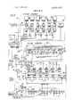
- FlGs. 1A through 1D inclusively are collectively a diagrammatic view. partly broken away, of a fluid delivery control and registration system incorporating an embodiment of the present invention.
- a fluid deliv ery control and registration system incorporating an embodiment of the present invention is provided for controlling and registering the fluid deliveries from twelve generally conventional fuel pumps 10. Only one fuel pump (i.e., Pump 1) and only the corresponding pump interlock circuit 12 and the corresponding pump interconnect circuit 14 are shown in the drawing for convenience.
- Pump 1 Only one fuel pump (i.e., Pump 1) and only the corresponding pump interlock circuit 12 and the corresponding pump interconnect circuit 14 are shown in the drawing for convenience.
- the fluid delivery control and registration system comprises a plurality of manually operable controls and a display register 16 for selectively displaying the cost and volume of the fuel deliveries from the twelve pumps and the total volume and total cost of each of three grades of fuel, herein designated grades A, B and c, delivered from the twelve pumps.
- the display register 16 and the manually operable controls are preferably provided on a single console and the console is preferably located to permit a console operator to view a dispensing operation at each of the pumps as well as to control and register each delivery.
- the system has primary utility in providing for self-service delivery fuel and such that each customer can handle his own fuel delivery after appropriate authorization is given by the console operator and then pay the console operator for the fuel delivery.
- the system comprises a timing circuit 18 for sequentially generating individual and binary timing signals for properly coordinating and/or sychronizing certain logic processing functions of the system.
- the timing circuit 18 comprises a l MHZ clock 20 which steps a timing pulse ring counter 22 for sequentially generating timing pulses TPO through TP -8 in corresponding output leads of the timing counter 22.
- the TP-8 timing pulse is similarly employed to step a digit ring counter 24 for sequentiaily generating digit pulses D-l through D-6 in corresponding output leads of the digit counter 24.
- the D-6 pulse is used to step a pump selector ring counter 26 for sequentially generating binary pump address signals.
- a decoder 30 is operated by the binary address signals for sequentially generating pump pulses P-l through Pl2 in corresponding output leads of the decoder 30.
- the TP-8 timing pulse is also connected via a D-6 pulse controlled gate 31 for stepping a memory address counter 32only five steps for each sixdigit pulse cycle of the digit counter 24for sequentially addressing the memory digits of memories 34 (which preferably have 64-digits but which use only 60- digits in the shown embodiment) of an A memory circuit 36 and an identical B memory circuit 38.
- a suitable reset circuit 40 is operated by the binary memory address output of the memory address counter 32 to reset the counter 22, 24, 26 and 32 at the completion of each 60 digit cycle of the memory address-and therefore at the completion of twelve full digit cycles of the digit counter 24 and one full cycle of the decoder 30and to thereupon initiate a succeeding digit cycle and synchronize the counters.
- the timing circuit provides consecutive Pl through P-l2 pump pulses and a synchronized binary output signal designating the pump.
- a synchronized binary output signal designating the pump.
- six sequential digit pulses D-l through D-6 are provided and for each digit pulse nine sequential timing pulses TP-O through TP-8 are provided.
- a pump selector 43 comprising a line of twelve pump push buttons 44 is provided for individually registering with the display register 16 the cost and/or volume of a fuel delivery from each pump for individually determining the memory status for each pump and for individually clearing the pump memories.
- Each selector 'button 44 is connected to the corresponding P-l through P-l2 pump lead of the decoder 30.
- the pump selector push buttons 44 are mechanically interlocked so that only one push button may be depressed at a time and such that a single P-l through P-l2 pulse is transmitted to a pump selector output 45 in accordance with the push button 44 which is depressed.
- a presettable grade selector 50 is provided for generating synchronized grade pulses in its three output leads representing the grade of each pump.
- the grade selector 50 has twelve input leads connected to the twelve P-l through P-12 pump leads and a suitable buffer diode 56 between each input lead and a terminal 57.
- the terminals are adapted to be selectively connected to the grade output terminals 58 for presetting the grade selector in accordance with the grade delivered from each pump.
- pumps 1-5 are shown connected to the grade A terminal, pumps 6-8 are connected to the grade B terminal and pumps 9-12 are connected to grade C terminal, the connections would be made as appropriate for each of the 12 pumps.
- a line of 12 pump authorization buttons 60 are provided for authorizing fuel deliveries from the 12 pumps.
- An authorization request button 62 is also provided at each pump for requesting authorization of a fuel delivery.
- a request authorization signal from the push button 62 sets a request authorization flip-flop 64.
- the flip-flop 64 in combination with a suitable flasher 66 (used for all 12 pumps) thereupon operate, via gates 68 and 70 to flash a push button lamp (not shown) at the corresponding authorization push button on and off, and thereby signal the console operator that a fuel delivery is requested.
- the corresponding authorization button 60 is connected, via an AND gate 72, to set an authorization flip-flop 74 and thereby provide an authorization signal transmitted via gate 76 to authorize the delivery of fuel from the corresponding fuel pump 10.
- the authorization signal is also applied to the gate 70 to hold the push button lamp on and thereby indicate that a delivery has been authorized.
- the pump interlock circuit 12 also employs a manual override switch 80 for maintaining the corresponding pump active, for example for attendant made deliveries.
- an emergency push button 82 is connected to the gate 76 for deenergizing the pump at any time.
- the pump 10 has an operating handle 90 mounted adjacent the usual fuel delivery nozzle receptacle so that the handle 90 must be placed in its vertical of of position before the delivery nozzle 91 can be returned to its receptacle at the end of a fuel delivery and cannot be moved to its horizontal or on position until after the nozzle 91 is removed from its storage receptacle.
- a suitable electric reset 92 of the pump such that when the handle 90 is placed in its on" or horizontal position, the electric reset 92 is energized to reset the volume and cost registers 93, 94 of the pump computer 96.
- a status signal is thereupon transmitted to a gate 104 to generate a memory clear signal in the memory clear lead l06-for clearing the corresponding pump memory section of the appropriate memory circuit 36, 38.
- the gate 104 is also connected to a pulse control gate 108 for transmitting cost pulses from a pump pulse generator 110 via lead 112 to a pulse scanner 114 of a scanning circuit 116. Accordingly, cost pulses are transmitted to the scanner 114 only while the pump 10 is active for delivering fuel and pulses cannot be transtor is also reset with the cost register 94 so that the pulse timing remains accurate.
- a pulse is generated by a single shot to reset the flip-flops 64 and 74 and thereby deactive the pump and turn off the pump authorization button lamp.
- the pulse generated by the single shot 120 also operates to set a first control flip-flop 122 and, if the flip-flop 122 is already set, to set, via gate 124, a second control flip-flop 126.
- the flip-flop 122 is connected via a lead 123 to apply a memory select signal to a corresponding pump input ofa memory select scanner 125.
- the flip-flop 122 is also connected via a gate to a lamp A scanner 132 to light (as here-inafter described) a lamp (not shown) associated with a memory A button 133 to indicate that the A memory section for the corresponding pump is in use.
- the flip-flop 126 is connected to a lamp B scanner 134 to light (as hereinafter described) a lamp (not shown) associated with a memory B button 135 and thereby indicate that the B memory section for corresponding pump is in use.
- the flip-flops 122, 126 are also connected (a) via a gate to the gate 72 to prevent a succeeding authorization when both available memory sections are in use and (b) via a gate 141 and lead 142 to selectively energize a lamp (not shown) associated with the corresponding pump selector button 44 when either or both of the memory sections are in use.
- the A and B memory sections for each pump may be individually cleared (upon the commencement of the succeeding delivery with the memory clear signal transmitted via lead 106) by simultaneously depressing the appropriate memory button 133, 135 and a clear button 143.
- a gate 144 is timely pulsed by the pump selector output pulse to transmit a clear pulse via a corresponding memory gate 145, 146 to the A and B memory clear decoders 149, respectively.
- the scanners 132, 134 and the decoders 149 and 150 are operated by the binary pump address signals such that (a) the pump lamp signals from each pump are transmitted to operate the lamps when the corresponding pump selector button is depressed and (b) the clear pulses are transmitted to clear the memory sections for a pump when the corresponding pump selector button is depressed. More particularly, when a pump selector button is depressed, the memory A clear signal is transmitted to the corresponding pump interlock circuit 12 to set a memory A clear flip-flop and the memory B clear signal is transmitted to reset the second control flip-flop 126.
- the flip-flop 160 is connected to gate 130 to turn off the memory A push button lamp.
- the first control flip-flop 122 is not, however, reset if the pump is then active and a gate 164 is connected for transmitting a reset signal for resetting the first control flip-flop 122 when the pump is deactivated and for also resetting the flip-flop 160.
- the delayed reset of the first control flip-flop 122 is provided for preventing switching memory circuits by switching the memory select signal in the lead 123 during the delivery of fuel.
- the output leads from the A and B lamp scanners 132, 134 are connected to gates which are pulsed by the pump selector output pulse.
- a flip-flop 172 is set to energize the lamp (not shown) associated with the memory A push button 133.
- the pump selector output pulse is transmitted via a gate 174 to reset the flipflop 172 and deenergize the memory A push button lamp.
- An identical system is provided for energizing and deenergizing the memory B push button lamp via the scanner 134.
- the cost pulses from the active pumps are transmitted to the pulse scanner 114 by the corresponding cost pulse leads 112.
- the memory clear signal for each pump is transmitted to a memory clear scanner 107 via a corresponding pump lead 106 and the memory select signals are transmitted via respective memory select leads 123 to a memory select scanner 125.
- the scanning circuit 116 provides for sequentially transmitting the cost pulses and control signals received from the pump interlock circuits 12 for proper operation of the A and B memory circuits 36, 38. Also, the cost pulses are transmitted via the scanning circuit 116 for operating a totalizer circuit 190 using an eighteen-digit memory 192 (Le, six-digits for each of the three available fuel grades A, B and C) for accumulating the total cost (in dollars in the shown embodiment) of each fuel grade delivered by all of the pumps connected for delivering that grade.
- the scanning circuit 116 employs a l2-digit memory 200 (preferably having l6-digits but using only l2- digits in the present embodiment) which is addressed in synchronism with the scanners 114, 107, and 125 by the binary pump address signals for transmitting and storing each cost pulse and each memory clear signal received from each pump interlock circuit 12 via the pulse scanner 114 and memory clear scanner 107. More particularly during each pump pulse interval any generated cost pulse from the corresponding pump is transmitted through the scanner 114, and then via a gate 202 during the succeeding TP-2 timing pulse of the D-1 digit pulse to temporarily set a flip-flop 204.
- the flip-flop 204 thereupon transmits a cost pulse signal via a gate 205 and either an A memory gate 206 or a B memory gate 207 as an input pulse to the respective memory circuit 36 or 38.
- the cost pulse signal is also written into the corresponding memory digit by the immediately following TP-6 timing pulse, and the flipflop 204 is then reset by the immediately following timing pulse TP-7.
- the pulse duration of each cost pulse transmitted to the scanner 114 is substantially longer than a complete scanner cycle such that each cost pulse is operative to set the flip-flop 204 several times during several successive cycles of the scanner 114.
- an output cost pulse signal is transmitted to the appropriate memory circuit 36 or 38 (at timing pulse TP-4 of digit pulse D-l) only once because the stored cost pulse signal in the corresponding memory digit is thereafter operative to make the control gate 205 nonconductive.
- the cost pulse signal applied to the scanner 114 terminates, the corresponding memory digit is cleared by the TP-6 write pulse to permit a succeeding cost pulse to be transmitted through the control gate 205.
- a memory clear signal transmitted to the clear scanner is similarly analyzed and transmitted via identically numbered circuitry to set a flip-flop 210 which transmits an output memory clear signal via either an A memory gate 212 or a B memory gate 214 to the appropriate memory circuit 36 or 38.
- the output memory clear signal is applied to the appropriate memory circuit during the interval between the TP-4 timing pulse of the D-1 digit pulse and the TP-7 timing pulse of D-6 digit pulse for fully resetting the five corresponding pump digits of the memory circuit whereupon the flip-flop 210 is reset via a gate 218.
- the memory select signal from each pump interlock circuit 12 is transmitted during the corresponding pump pulse via the memory select scanner for timely operating the A memory gates 206, 212 or the B memory gates 207, 214.
- the A memory gates 206, 212 will be effective to transmit the clear signal to the A memory circuit 36 (for clearing the corresponding five-digit pump memory section of the memory 34) and then transmit succeeding cost pulses to the A memory circuit 36 for accumulating the cost amount of the succeeding fuel delivery. If the first control flip-flop 122 is in its set conditionn, the clear signal and succeeding cost pulses are transmitted to the B memory circuit 38 for similarly clearing the corresponding pump memory section and accumulating the cost amount of the succeeding fuel delivery in the B memory circuit 38.
- a bank of gates 217-219 are also timely operated by corresponding grade pulses to transmit the cost pulse signals from the gate 205 to cost division circuits 232-234 for the three available grades.
- Each division circuit 232-234 transmits an output pulse for each one hundred input pulses (and accordingly are in effect one dollar pulses) via a gate 236 to the totalizer circuit 190.
- the cost pulse signals for each pump are transmitted to the selected memory circuit for accumulation of the cost amount of fuel delivered from the pump.
- the memories 34 are addressed in synchronism with the corresponding cost pulse trains such that the corresponding five-digit memory section of the selected memory 34 will accumulate the cost (up to a maximum of $999.99) of the fuel delivered.
- the cost pulses are supplied to a gate 250 of the selected memory circuit 36, 38 to add a count of one to a BCD counter 252 which has been preset (with timing pulse TP-2 of digit pulse D-l) with the existing digit count of the first digit of the accumulated cost.
- the count of the counter 252 i.e., the prior digit count plus one
- timing pulse TP-7 is then written into the first digit by timing pulse TP-7.
- any carry signal from the digit count is added to the succeeding digit.
- the carry signal from the BCD counter 252 initially sets a flip-flop 253 which then transmits the carry signal via a gate 254 to a second flip-flop 256 at the TP-2 timing pulse of the following timing pulse cycle whereupon the first flip-flop 253 is reset.
- the carry signal is then transmitted from the flipflop 256 via a gate 258 and the gate 250 to the counter 252 at timing pulse TP-6.
- the count in the counter 252 is then stored in the memory digit.
- each five-digit pump memory section of the memory 34 accumulates the total cost of fuel delivered by the corresponding pump to two decimal places.
- the five-digit memory 'section for a given pump is selectively cleared by the clear signal transmitted via the gate 212 or 214, as previously explained, upon the commencement of each fuel delivery.
- the totalizer circuit comprises an 18-digit memory 192 for storing the total cost amount in dollars of I each available fuel grade delivered by the delivery system.
- the one dollar cost pulses transmitted via the gate 236 to the totalizer circuit 190 are handled-in exactly the same manner as the l-cent cost pulses are handled in the A and B memory circuits 36, 38--to accumulate the total cost delivered of the three grades of fuel and in the respective six-digit memory sections of the memory 192.
- the memory 192 is addressed by a memory address circuit 270 which is initially set, during each pump pulse, by the respective grade pulse and is then sequentially stepped by the succeeding TP-8 timing pulses.
- the totalizer circuit memory 192 may be manually reset, for example, at the end of the day or at the end of each 8 hour shift after the volume and cost totals are suitably recorded as described, for which purpose a suitable manual reset button 280 is connected to the memory 192 for clearing the memory 192.
- the reset button 280 is also connected for simultaneously clearing the division circuits 232-234.
- the accumulated cost amount of each fuel delivery from each pump can be selectively registered on the display register 16 merely by depressing the corresponding pump selector button 44 and depressing the appropriate memory select button 133, l35'for that delivery.
- the desired delivery cost data can be displayed by depressing the memory select button 133, 135 for the appropriate memory circuit.
- the memory select buttons I33, 135 are connected, via control gates 296, 298 respectively, to a bank of A memory data control gates 300 and a bank of B memory data control gates 302 for selectively connecting the BCD memory outputs via a cost data bus 306 and a cost/volume selector 308 to BCD digit storage registers 310 of the display register 16.
- the BCD digit registers 310 are sequentially loaded via gates 314 by the digit pulses D-l through D-6 of the selected pump pulse. Decoder driver circuits 320 provide for operating digit display registers 322 in accordance with the BCD outputs of the digit storage registers 310 such that the accumulated cost for the selected pump delivery is displayed by the display registers 322.
- the display registers may, for example be 7- bar, FIG. 8 type display tubes manufactured by Radio Corporation Of America under the trademark NUMl- TRON.
- a decimal point driver 326 is provided for energizing the decimal point 328 of the second order digit display 322 such that the register 16 will properly display the cost amount of the delivery to two decimal places. Also, as the cost is only accumulated to five places in the memories 34, the sixth or highest order digit display 322 is held deenergized or blanked by a signal from an inverter 330 applied to the sixth place decoder driver 320. The fifth or next highest order digit display decoder driver 320 may also be similarly connected as shown in dotted lines where a four place cost display (i.e., providing a maximum cost display of $99.99) is sufficient.
- the volume amount of the selected fuel delivery (which corresponds to the selected cost amount) may be selectively registered with the register 16 by additionally depressing and holding depressed a volume select button 340.
- the volume select button 340 is conand load the volume computer 350.
- the clear and load pulse so generated is transmitted via a control gate 354 to (a) clear six BCD decade counters 360 of a volume counting section 362, (b) clear a simulated cost computer 364 and (c) reset three price control flip-flops 365-367 of the cost computer 364.
- the selected BCD cost data transmitted via the cost data bus 306 is sequentially loaded into the first five place BCD cost registers 370 by means of the digit pulses D1 through D5 applied to the registers via the control gates 372.
- the highest order register 370 is maintained disconnected from the cost data bus 306 by a bank 374 of control gates when computing the volume amount of an individual delivery and, therefore, when a six place storage register is not required. Thus, in effect, the highest place register 370 is then set at binary zero.
- the clear and load signal also operates a suitable delay circuit 378 which, after the volume computer 350 is cleared and the registers 370 are loaded, generates a control signal for making the gate 354 nonconductive and for making a gate 382 conductive for supplying clock pulses (which function as simulated volume pulses) via a second control gate 384 to the simulated cost computer 364.
- the cost computer may, for example be like that disclosed in U.S. Pat. No. 3,696,236 of Crawford M. Kus entitled Computing Device and dated Oct. 3,1972.
- a bank 390 of three BCD price switches 392 is provided for each of the three available grades of fuel.
- Each switch bank 390 is preset in accordance with the preestablished unit volume price for the corresponding grade.
- the switch banks 390 are selectively activated by the application of the clear and load timing pulse and grade timing pulses to the control gates 395-397 which then transmits a pulse for setting one of the flip-flops 365-367 in accordance with the preset fuel grade for the depressed selector button 44 for activating the corresponding price switch bank 390.
- the simulated volume pulses passing through the control gate 384 are supplied to the lowest order BCD decade counter 360 of the volume counting section 362 to accumulate a volume count in the volume counting section 362.
- the simulated volume pulses are supplied to the cost computer 364 to accumulate a cost count in a six place BCD cost accumulator 400 of the computer 364.
- a suitable comparator circuit 402 is connected to the BCD readout leads of the cost registers 370 and to the BCD readout leads of the cost accumulator decades 404 such that when the accumulated cost in the accumulator 400 equals the preset cost in the registers 370, the comparator operates the control gate 384 to terminate the supply of simulated volume pulses to the cost computer 364 and volume accumulator 362.
- the volume amount accumulated in the volume accumulator 362 exactly corresponds to the cost amount of the selected fuel delivery stored in memory in accordance with the preestablished unit volume price of the fuel grade.
- the accumulated volume amount is continuously transmitted via banks 410 of digit pulse controlled gates 412 and the cost/volume selector 308 to the display register 16 for displaying the computed volume of the selected fuel delivery.
- a totalizer display button 420 and individual fuel grade buttons 421-423 are provided for selectively registering, with the display register 16, the total accumulated cost of each grade of fuel delivered.
- the gates 296, 298 are thereupon operated to disconnect the memory select buttons 133, 135 from the corresponding banks 300, 302 of data control gates.
- the blanking circuit to the display register 16 is deenergized and the decimal point driver 326 is operated to deenergize the second place decimal point 328.
- a first place decimal point could be connected as shown in broken lines to be energized to register the total cost amount of the first decimal place, in which event, the division circuits 232-234 would be divide by ten circuits rather than divide by one hundred circuits as shown.
- the individual grade buttons 421-423 are suitably mechanically interlocked so that only one button can be depressed at a time.
- the depressed button supplies a grade timing pulse via a control gate 425 to a bank 427 of BCD data control gates to sequentially supply the digital totalizer cost data for the selected grade via selector 308 to the display register 16 where it is then displayed (up to a maximum of $999,999).
- the total volume amount corresponding to the selected cost amount stored in the memory can be selectively registered with the display register 16 by additionally depressing and holding depressed the'volume select button 340. Thereupon, the totalizer cost data for the selected grade is transmitted to the volume computer 350 which then computes the corresponding volume amount in accordance with the transmitted total cost amount and the unit volume price of the selected grade of fuel. In this latter regard, the appropriate price control flip-flop 365-367 is set via the corresponding gate 395-397 by the grade timing pulse transmitted thereto from the depressed grade push button 421-423. The totalizer volume computed in the volume computer 350 is transmitted to the display register 16 for registration with the six register digits 322 (up to a minimum of 999,999 gallons).
- a multiple delivery station fluid delivery registration system for storing and registering the separate fluid deliveries at a plurality of delivery stations and for selectively controlling each delivery station for delivering fluid
- pulse generating means associated with each fluid delivery station for generating a pulse for each predetermined incremental amount of fluid delivered at the respective delivery station
- electronic storage memory circuit means having a plurality of separate electronic storage memory sections for each delivery station for separately accumulating and storing the amount of each of a corresponding plurality of separate fluid deliveries at the respective delivery station
- storage control means for operating the storage memory circuit means for separately accumulating and storing the amount of each of said corresponding plurality of separate fluid deliveries at each delivery station in the corresponding plurality of storage memory sections and in accordance with the number of pulses generated by the respective pulse generating means during the respective fluid deliveries
- first manually operable delivery control means manually operable for selectively activating each delivery station for making a single fluid delivery and separately selectively manually operable for each delivery station for selectively operating the storage control means for individually conditioning each corresponding storage memory section for accumulating and storing
- a multiple delivery station fluid delivery registration system comprising a plurality of separate storage memory circuits each having a said storage memory section for each delivery station adapted to be operated by the storage control means for accumulating and storing a single delivery at the respective delivery station, and wherein the storage control means is independently operable for each delivery station fluid delivery for operating a selected storage memory circuit for accumulating and storing the amount of the fluid delivery at the delivery station.
- each storage memory circuit comprises a memory with a plurality of memory sections for accumulating and storing fluid delivery amounts at-the plurality of delivery stations 'respectively and adapted to be addressed for individually addressing the memory sections
- the storage control means comprises memory circuit select means for each delivery station for generating a memory select signal for selecting the memory circuit into which the amount of the delivery at the station is to be accumulated and stored,- and multiplexing means for sequentially addressing the memory sections of the memory circuits in a predetermined order and sequentially scanning the respective memory circuit select means and pulse generating means in synchronism therewith for accumulating and storing the amount of a fluid delivery at each delivery station in a corresponding memory section of a memory circuit selected by the select signal of the respective memory select means.
- a multiple delivery station fluid delivery registration system according to claim 1 wherein the first manually operable means comprises manually operable clear means for selectively clearing the amount of each fluid delivery stored in the storage memory circuit means.
- a multiple delivery station fluid delivery registration system wherein the manually operable clear means comprises clearing means for each delivery station adapted to be selectively set for clearing the stored amount of a selected fluid delivery at the delivery station at the commencement of a succeeding delivery at the delivery station, and manually operable clear select means for selectively setting the clearing means for each station.
- a multiple delivery station fluid delivery registration system comprising separate storage control means for each delivery station having separate authorization circuit means for conditioning the respective delivery station for delivering fluid and memory circuit select means for individually selecting the respective plurality of separate memory sections into which the amount of the succeeding delivery at the station is to be accumulated and stored
- the first manually operable means comprises memory clear means for indivdually clearing the storage memory sections
- each memory circuit select means is operable for automatically selecting a respective storage memory section cleared by the manual clear means and for deactivating the respective authorization circuit means for conditioning the respective delivery station for delivering fluid if the clear means hasnt been operated to clear any of the respective memory sections.
- a multiple delivery station fluid delivery registration system for storing and registering the fluid deliveries at a plurality of delivery stations comprising pulse generating means associated with each fluid delivery station for generating a cost pulse for each predetermined incremental cost amount of fluid delivered at the station.
- electronic storage memory circuit means having a plurality of electronic accumulator sections for separately accumulating the cost amounts of fluid delivered at the delivery stations, respectively, presettable price volume computer means for computing the volume amount ofa selected fluid delivery stored in the accumulating means in accordance with the stored cost amount of the fluid delivery and a unit volume price for the corresponding fluid delivery station pre-established by the setting of the volume computer means, register means operable for registering the cost and volume amounts of each fluid delivery, and manually operable register control means for individlually selecting the electronic accumulator sections for selecting a fluid delivery stored in the accumulating means and for operating the register for registering the cost amount of the fluiddelivery stored in the selected accumulator section.
- volume computer means for additionally operating the volume computer means to compute the corresponding volume amount of the selected fluid delivery in accordance with the accumulated cost amount of the fluid delivery stored in the selected accumulator section and the pre-established unit volume price for the corresponding fluid delivery station and operate the register to register the computed volume amount computed by the volume computer means.
- a multiple delivery station fluid delivery registration system wherein the register means is operable for alternatively registering the cost and volume amounts of a selected fluid delivery and wherein the register control means is manually operable for alternatively operating the register means to register the cost amount of the selected fluid delivery stored in the accumulating means and operating the volume computer means to compute the corresponding volume amount of the selected fluid delivery and operate the register to register the volume amount computed by the volume computer means.
- a multiple delivery station fluid delivery registration system for a plurality of delivery stations adapted to deliver a plurality of different fluid products having respective preestablished unit volume prices
- the presettable volume computer means comprises unit volume price input means for each of the fluid products presettable for preestablishing the unit volume price of the respective fluid product, and price selection means for selectively activating the price input means for computing the volume amount of each selected fluid delivery in accordance with the unit volume price preestablished for the respective product.
- a multiple delivery station fluid delivery registration system comprising synchronizing means for repetitively generating a series of a plurality of sequential timing pulses for the plurality of delivery stations respectively and for generating respective product pulses for the respective products respectively in synchronism therewith and wherein the price selection means is operable by the timing pulse for the selected delivery station and the respective product pulse for selectively activating the respective price input means.
- a fluid delivery registration system for storing and registering the amounts of the fluid deliveries at a plurality of fluid delivery stations which are operable to deliver a plurality of different fluid products with respective pre-established unit volume prices, comprising pulse generating means associated with each fluid delivery station for generating a pulse for each predetermined incremental amount of fluid delivered at the station, first electronic storage memory circuit means adapted to be pulsed for separately accumulating and storing the amount of each fluid delivery at each delivery station, second electronic totalizer storage memory circuit means adapted to be pulsed for separately accumulating and storing the total amount of each fluid product delivered by all of the delivery stations, storage memory control means comprising timing means for repetitively generating a series of sequential station timing pulses and respective product timing pulses in synchronism therewith and multiplexing means operable by the station timing pulses for transmitting generated pulses from each station pulse generating means to the first storage memory circuit means for separately accumulating and storing the amounts of the fluid deliveries at the delivery stations and simultaneously operable by the respective product timing pulses for transmitting the generated pulses from the
- a fluid delivery registration system comprising an individual electronic delivery memory section for each station having a fixed plurality of memory digits of ascending order for accumulating and storing the amount of an individual delivery at the station
- the electronic totalizer storage memory circuit means comprises an individual electronic totalizer memory section for each product hav- 14 comprises blanking means for automatically blanking the highest order digits in excess of the number of digits of the individual delivery memory sections when the register means is operated for registering the amount of an individual fluid delivery.
Abstract
A twelve pump fuel delivery control and registration system for controlling self-service operation of each fuel pump and for selectively registering the volume and cost amounts of each fuel delivery for charging the self-service customers. The system is also selectively operable for registering the total cost and volume amounts of three available grades of fuel delivered by the 12 pumps.
Description
United States Patent [191 Brunone Apr. 15, 1975 FLUID DELIVERY CONTROL AND REGISTRATION SYSTEM [75] Inventor:
[73] Assignee: Veeder Industries, Inc., Hartford,
Conn.
[22] Filed: Sept. 12, 1973 [21] Appl. No.: 396,486
Peter P. Brunone, Vernon, Conn.
[52] U.S. Cl 235/l5l.34; 222/26; 235/92 FL [51] Int. Cl. G06f 15/56 [58] Field of Search 235/151.34, 92 FL; 222/23,
[56] References Cited UNITED STATES PATENTS 3,437,240 4/1969 Keeler 222/25 3,498,501 3/1970 Robbins et al.... 222/26 3,510,630 5/1970 Ryan et a1 222/26 X 3,580,42l 5/1971 Bickford 235/92 FL X INTERCONNECT CIRCUIT 3,666,928 5/1972 Burke et al. 235/92 FL 3,696,236 10/1972 Kus 235/l5l.34 3,751,642 8/1973 Todd et al. 235/151.34 3,756,463 9/1973 Gravina 222/26 3,756,630 9/1973 Bickford 235/15l.34
Primary Examiner-Felix D. Gruber Assistant Examiner-Jerry Smith Attorney, Agent, or FirmPrutzman, Hayes, Kalb & Chilton [57] ABSTRACT A twelve pump fuel delivery control and registration system for controlling self-service operation of each fuel pump and for selectively registering the volume and cost amounts of each fuel delivery for charging the self-service customers. The system is also selectively operable for registering the total cost and volume amounts of three available grades of fuel delivered by the 12 pumps.
12 Claims, 4 Drawing Figures PUMP SELECTOR MEMORY MEMORY MEMORY PTJENTEBAPRISIQYS 3,878,377
GRADE A FLUID DELIVERY CONTROL AND REGISTRATION SYSTEM BRIEF SUMMARY OF THE INVENTION The present invention relates to a fluid delivery control and registration system having notable utility for individually controlling and registering the fuel deliver ies at a plurality of fuel pumps.
It is a primary aim of the present invention to provide a new and improved fuel delivery control and registration system which permits a single console operator to control the self-service deliveries of fuel from each of a plurality of fuel pumps and for selectively registering the cost and/or volume amounts of each fuel delivery for charging the self-service customers for the fuel deliveries.
It is another aim of the present invention to provide a new and improved fuel delivery control and registration system useful with conventional fuel delivery pumps.
It is a further aim of the present invention to provide an new and improved fuel delivery registration system for electronically accumulating and registering the cost and/or volume amounts of each fuel delivery in accordance with the preestablished unit volume price.
It is another aim of the present invention to provide a new and improved fuel delivery registration system which is operable for registering the fuel deliveries from a large number of fuel delivery pumps.
It is a further aim of the present invention to provide a new and improved fuel pump delivery registration system for selectively registering the cost and/or volume amounts ofa plurality of prior fluid deliveries from each fuel pump.
It is another aim of the present invention to provide a new and improved fuel delivery control and registration system which permits activation of each pump for a succeeding delivery prior to recording the immediately preceding fuel delivery.
Other objects will be in part obvious and in part pointed out more in detail hereinafter.
A better understanding of the invention will be obtained from the following detailed description and the accompanying drawings of an illustrative application of the invention.
BRIEF DESCRIPTION OF THE DRAWINGS In the drawings:
FlGs. 1A through 1D inclusively are collectively a diagrammatic view. partly broken away, of a fluid delivery control and registration system incorporating an embodiment of the present invention.
DESCRIPTION OF THE PREFERRED EMBODIMENT Referring now to the drawings in detail, a fluid deliv ery control and registration system incorporating an embodiment of the present invention is provided for controlling and registering the fluid deliveries from twelve generally conventional fuel pumps 10. Only one fuel pump (i.e., Pump 1) and only the corresponding pump interlock circuit 12 and the corresponding pump interconnect circuit 14 are shown in the drawing for convenience.
The fluid delivery control and registration system comprises a plurality of manually operable controls and a display register 16 for selectively displaying the cost and volume of the fuel deliveries from the twelve pumps and the total volume and total cost of each of three grades of fuel, herein designated grades A, B and c, delivered from the twelve pumps. The display register 16 and the manually operable controls are preferably provided on a single console and the console is preferably located to permit a console operator to view a dispensing operation at each of the pumps as well as to control and register each delivery. The system has primary utility in providing for self-service delivery fuel and such that each customer can handle his own fuel delivery after appropriate authorization is given by the console operator and then pay the console operator for the fuel delivery.
The system comprises a timing circuit 18 for sequentially generating individual and binary timing signals for properly coordinating and/or sychronizing certain logic processing functions of the system. The timing circuit 18 comprises a l MHZ clock 20 which steps a timing pulse ring counter 22 for sequentially generating timing pulses TPO through TP -8 in corresponding output leads of the timing counter 22. The TP-8 timing pulse is similarly employed to step a digit ring counter 24 for sequentiaily generating digit pulses D-l through D-6 in corresponding output leads of the digit counter 24. And the D-6 pulse is used to step a pump selector ring counter 26 for sequentially generating binary pump address signals. A decoder 30 is operated by the binary address signals for sequentially generating pump pulses P-l through Pl2 in corresponding output leads of the decoder 30. The TP-8 timing pulse is also connected via a D-6 pulse controlled gate 31 for stepping a memory address counter 32only five steps for each sixdigit pulse cycle of the digit counter 24for sequentially addressing the memory digits of memories 34 (which preferably have 64-digits but which use only 60- digits in the shown embodiment) of an A memory circuit 36 and an identical B memory circuit 38. A suitable reset circuit 40 is operated by the binary memory address output of the memory address counter 32 to reset the counter 22, 24, 26 and 32 at the completion of each 60 digit cycle of the memory address-and therefore at the completion of twelve full digit cycles of the digit counter 24 and one full cycle of the decoder 30and to thereupon initiate a succeeding digit cycle and synchronize the counters.
Thus, the timing circuit provides consecutive Pl through P-l2 pump pulses and a synchronized binary output signal designating the pump. During each pump pulse, six sequential digit pulses D-l through D-6 are provided and for each digit pulse nine sequential timing pulses TP-O through TP-8 are provided.
A pump selector 43 comprising a line of twelve pump push buttons 44 is provided for individually registering with the display register 16 the cost and/or volume of a fuel delivery from each pump for individually determining the memory status for each pump and for individually clearing the pump memories. Each selector 'button 44 is connected to the corresponding P-l through P-l2 pump lead of the decoder 30. The pump selector push buttons 44 are mechanically interlocked so that only one push button may be depressed at a time and such that a single P-l through P-l2 pulse is transmitted to a pump selector output 45 in accordance with the push button 44 which is depressed.
A presettable grade selector 50 is provided for generating synchronized grade pulses in its three output leads representing the grade of each pump. The grade selector 50 has twelve input leads connected to the twelve P-l through P-12 pump leads and a suitable buffer diode 56 between each input lead and a terminal 57. The terminals are adapted to be selectively connected to the grade output terminals 58 for presetting the grade selector in accordance with the grade delivered from each pump. Although pumps 1-5 are shown connected to the grade A terminal, pumps 6-8 are connected to the grade B terminal and pumps 9-12 are connected to grade C terminal, the connections would be made as appropriate for each of the 12 pumps.
A line of 12 pump authorization buttons 60 are provided for authorizing fuel deliveries from the 12 pumps. An authorization request button 62 is also provided at each pump for requesting authorization of a fuel delivery. A request authorization signal from the push button 62 sets a request authorization flip-flop 64. The flip-flop 64 in combination with a suitable flasher 66 (used for all 12 pumps) thereupon operate, via gates 68 and 70 to flash a push button lamp (not shown) at the corresponding authorization push button on and off, and thereby signal the console operator that a fuel delivery is requested. The corresponding authorization button 60 is connected, via an AND gate 72, to set an authorization flip-flop 74 and thereby provide an authorization signal transmitted via gate 76 to authorize the delivery of fuel from the corresponding fuel pump 10. The authorization signal is also applied to the gate 70 to hold the push button lamp on and thereby indicate that a delivery has been authorized. The pump interlock circuit 12 also employs a manual override switch 80 for maintaining the corresponding pump active, for example for attendant made deliveries. Also, an emergency push button 82 is connected to the gate 76 for deenergizing the pump at any time.
[n a conventional manner, the pump 10 has an operating handle 90 mounted adjacent the usual fuel delivery nozzle receptacle so that the handle 90 must be placed in its vertical of of position before the delivery nozzle 91 can be returned to its receptacle at the end of a fuel delivery and cannot be moved to its horizontal or on position until after the nozzle 91 is removed from its storage receptacle. Upon authorization, power is supplied to a suitable electric reset 92 of the pump such that when the handle 90 is placed in its on" or horizontal position, the electric reset 92 is energized to reset the volume and cost registers 93, 94 of the pump computer 96. After the registers 93, 94 are reset to zero, power is supplied to the fuel delivery pump motor 98 to condition the pump 10 for delivering fuel. A status signal is thereupon transmitted to a gate 104 to generate a memory clear signal in the memory clear lead l06-for clearing the corresponding pump memory section of the appropriate memory circuit 36, 38. The gate 104 is also connected to a pulse control gate 108 for transmitting cost pulses from a pump pulse generator 110 via lead 112 to a pulse scanner 114 of a scanning circuit 116. Accordingly, cost pulses are transmitted to the scanner 114 only while the pump 10 is active for delivering fuel and pulses cannot be transtor is also reset with the cost register 94 so that the pulse timing remains accurate.
At the completion of a delivery when the handle 90 is returned to its vertical or off" position, or when the pump is deactivated by the emergency push button 82, a pulse is generated by a single shot to reset the flip- flops 64 and 74 and thereby deactive the pump and turn off the pump authorization button lamp. The pulse generated by the single shot 120 also operates to set a first control flip-flop 122 and, if the flip-flop 122 is already set, to set, via gate 124, a second control flip-flop 126. The flip-flop 122 is connected via a lead 123 to apply a memory select signal to a corresponding pump input ofa memory select scanner 125. The flip-flop 122 is also connected via a gate to a lamp A scanner 132 to light (as here-inafter described) a lamp (not shown) associated with a memory A button 133 to indicate that the A memory section for the corresponding pump is in use. Similarly, the flip-flop 126 is connected to a lamp B scanner 134 to light (as hereinafter described) a lamp (not shown) associated with a memory B button 135 and thereby indicate that the B memory section for corresponding pump is in use. The flip- flops 122, 126 are also connected (a) via a gate to the gate 72 to prevent a succeeding authorization when both available memory sections are in use and (b) via a gate 141 and lead 142 to selectively energize a lamp (not shown) associated with the corresponding pump selector button 44 when either or both of the memory sections are in use.
The A and B memory sections for each pump may be individually cleared (upon the commencement of the succeeding delivery with the memory clear signal transmitted via lead 106) by simultaneously depressing the appropriate memory button 133, 135 and a clear button 143. As a result, a gate 144 is timely pulsed by the pump selector output pulse to transmit a clear pulse via a corresponding memory gate 145, 146 to the A and B memory clear decoders 149, respectively.
The scanners 132, 134 and the decoders 149 and 150 are operated by the binary pump address signals such that (a) the pump lamp signals from each pump are transmitted to operate the lamps when the corresponding pump selector button is depressed and (b) the clear pulses are transmitted to clear the memory sections for a pump when the corresponding pump selector button is depressed. More particularly, when a pump selector button is depressed, the memory A clear signal is transmitted to the corresponding pump interlock circuit 12 to set a memory A clear flip-flop and the memory B clear signal is transmitted to reset the second control flip-flop 126. The flip-flop 160 is connected to gate 130 to turn off the memory A push button lamp. The first control flip-flop 122 is not, however, reset if the pump is then active and a gate 164 is connected for transmitting a reset signal for resetting the first control flip-flop 122 when the pump is deactivated and for also resetting the flip-flop 160. The delayed reset of the first control flip-flop 122 is provided for preventing switching memory circuits by switching the memory select signal in the lead 123 during the delivery of fuel.
The output leads from the A and B lamp scanners 132, 134 are connected to gates which are pulsed by the pump selector output pulse. Thus, for example, when the pump 1 selector button 44 is depressed and a memory A lamp signal is transmitted to the scanner 132 from pump 1, a flip-flop 172 is set to energize the lamp (not shown) associated with the memory A push button 133. When the lamp signal is terminated upon the setting of the flip-flop 160, the pump selector output pulse is transmitted via a gate 174 to reset the flipflop 172 and deenergize the memory A push button lamp. An identical system is provided for energizing and deenergizing the memory B push button lamp via the scanner 134.
The cost pulses from the active pumps are transmitted to the pulse scanner 114 by the corresponding cost pulse leads 112. Similarly, the memory clear signal for each pump is transmitted to a memory clear scanner 107 via a corresponding pump lead 106 and the memory select signals are transmitted via respective memory select leads 123 to a memory select scanner 125.
The scanning circuit 116 provides for sequentially transmitting the cost pulses and control signals received from the pump interlock circuits 12 for proper operation of the A and B memory circuits 36, 38. Also, the cost pulses are transmitted via the scanning circuit 116 for operating a totalizer circuit 190 using an eighteen-digit memory 192 (Le, six-digits for each of the three available fuel grades A, B and C) for accumulating the total cost (in dollars in the shown embodiment) of each fuel grade delivered by all of the pumps connected for delivering that grade.
The scanning circuit 116 employs a l2-digit memory 200 (preferably having l6-digits but using only l2- digits in the present embodiment) which is addressed in synchronism with the scanners 114, 107, and 125 by the binary pump address signals for transmitting and storing each cost pulse and each memory clear signal received from each pump interlock circuit 12 via the pulse scanner 114 and memory clear scanner 107. More particularly during each pump pulse interval any generated cost pulse from the corresponding pump is transmitted through the scanner 114, and then via a gate 202 during the succeeding TP-2 timing pulse of the D-1 digit pulse to temporarily set a flip-flop 204. The flip-flop 204 thereupon transmits a cost pulse signal via a gate 205 and either an A memory gate 206 or a B memory gate 207 as an input pulse to the respective memory circuit 36 or 38. The cost pulse signal is also written into the corresponding memory digit by the immediately following TP-6 timing pulse, and the flipflop 204 is then reset by the immediately following timing pulse TP-7. The pulse duration of each cost pulse transmitted to the scanner 114 is substantially longer than a complete scanner cycle such that each cost pulse is operative to set the flip-flop 204 several times during several successive cycles of the scanner 114. However, an output cost pulse signal is transmitted to the appropriate memory circuit 36 or 38 (at timing pulse TP-4 of digit pulse D-l) only once because the stored cost pulse signal in the corresponding memory digit is thereafter operative to make the control gate 205 nonconductive. After the cost pulse signal applied to the scanner 114 terminates, the corresponding memory digit is cleared by the TP-6 write pulse to permit a succeeding cost pulse to be transmitted through the control gate 205. A memory clear signal transmitted to the clear scanner is similarly analyzed and transmitted via identically numbered circuitry to set a flip-flop 210 which transmits an output memory clear signal via either an A memory gate 212 or a B memory gate 214 to the appropriate memory circuit 36 or 38. The output memory clear signal is applied to the appropriate memory circuit during the interval between the TP-4 timing pulse of the D-1 digit pulse and the TP-7 timing pulse of D-6 digit pulse for fully resetting the five corresponding pump digits of the memory circuit whereupon the flip-flop 210 is reset via a gate 218.
The memory select signal from each pump interlock circuit 12 is transmitted during the corresponding pump pulse via the memory select scanner for timely operating the A memory gates 206, 212 or the B memory gates 207, 214. Thus, with the first control flip-flop 122 of the pump interlock circuit 12 in a cleared or reset condition, the A memory gates 206, 212 will be effective to transmit the clear signal to the A memory circuit 36 (for clearing the corresponding five-digit pump memory section of the memory 34) and then transmit succeeding cost pulses to the A memory circuit 36 for accumulating the cost amount of the succeeding fuel delivery. If the first control flip-flop 122 is in its set conditionn, the clear signal and succeeding cost pulses are transmitted to the B memory circuit 38 for similarly clearing the corresponding pump memory section and accumulating the cost amount of the succeeding fuel delivery in the B memory circuit 38.
A bank of gates 217-219 are also timely operated by corresponding grade pulses to transmit the cost pulse signals from the gate 205 to cost division circuits 232-234 for the three available grades. Each division circuit 232-234 transmits an output pulse for each one hundred input pulses (and accordingly are in effect one dollar pulses) via a gate 236 to the totalizer circuit 190.
The cost pulse signals for each pump are transmitted to the selected memory circuit for accumulation of the cost amount of fuel delivered from the pump. The memories 34 are addressed in synchronism with the corresponding cost pulse trains such that the corresponding five-digit memory section of the selected memory 34 will accumulate the cost (up to a maximum of $999.99) of the fuel delivered. More particularly, the cost pulses are supplied to a gate 250 of the selected memory circuit 36, 38 to add a count of one to a BCD counter 252 which has been preset (with timing pulse TP-2 of digit pulse D-l) with the existing digit count of the first digit of the accumulated cost. The count of the counter 252 (i.e., the prior digit count plus one) is then written into the first digit by timing pulse TP-7. Any carry signal from the digit count is added to the succeeding digit. The carry signal from the BCD counter 252 initially sets a flip-flop 253 which then transmits the carry signal via a gate 254 to a second flip-flop 256 at the TP-2 timing pulse of the following timing pulse cycle whereupon the first flip-flop 253 is reset. The carry signal is then transmitted from the flipflop 256 via a gate 258 and the gate 250 to the counter 252 at timing pulse TP-6. The count in the counter 252 is then stored in the memory digit. Thus, each five-digit pump memory section of the memory 34 accumulates the total cost of fuel delivered by the corresponding pump to two decimal places. The five-digit memory 'section for a given pump is selectively cleared by the clear signal transmitted via the gate 212 or 214, as previously explained, upon the commencement of each fuel delivery.
The totalizer circuit comprises an 18-digit memory 192 for storing the total cost amount in dollars of I each available fuel grade delivered by the delivery system. The one dollar cost pulses transmitted via the gate 236 to the totalizer circuit 190 are handled-in exactly the same manner as the l-cent cost pulses are handled in the A and B memory circuits 36, 38--to accumulate the total cost delivered of the three grades of fuel and in the respective six-digit memory sections of the memory 192. The memory 192 is addressed by a memory address circuit 270 which is initially set, during each pump pulse, by the respective grade pulse and is then sequentially stepped by the succeeding TP-8 timing pulses.
The totalizer circuit memory 192 may be manually reset, for example, at the end of the day or at the end of each 8 hour shift after the volume and cost totals are suitably recorded as described, for which purpose a suitable manual reset button 280 is connected to the memory 192 for clearing the memory 192. The reset button 280 is also connected for simultaneously clearing the division circuits 232-234.
The accumulated cost amount of each fuel delivery from each pump can be selectively registered on the display register 16 merely by depressing the corresponding pump selector button 44 and depressing the appropriate memory select button 133, l35'for that delivery. (As the cost amounts of two separate fuel deliveries can be stored in the separate memory circuits 36, 38, the desired delivery cost data can be displayed by depressing the memory select button 133, 135 for the appropriate memory circuit.) The memory select buttons I33, 135 are connected, via control gates 296, 298 respectively, to a bank of A memory data control gates 300 and a bank of B memory data control gates 302 for selectively connecting the BCD memory outputs via a cost data bus 306 and a cost/volume selector 308 to BCD digit storage registers 310 of the display register 16. The BCD digit registers 310 are sequentially loaded via gates 314 by the digit pulses D-l through D-6 of the selected pump pulse. Decoder driver circuits 320 provide for operating digit display registers 322 in accordance with the BCD outputs of the digit storage registers 310 such that the accumulated cost for the selected pump delivery is displayed by the display registers 322. The display registers may, for example be 7- bar, FIG. 8 type display tubes manufactured by Radio Corporation Of America under the trademark NUMl- TRON.
A decimal point driver 326 is provided for energizing the decimal point 328 of the second order digit display 322 such that the register 16 will properly display the cost amount of the delivery to two decimal places. Also, as the cost is only accumulated to five places in the memories 34, the sixth or highest order digit display 322 is held deenergized or blanked by a signal from an inverter 330 applied to the sixth place decoder driver 320. The fifth or next highest order digit display decoder driver 320 may also be similarly connected as shown in dotted lines where a four place cost display (i.e., providing a maximum cost display of $99.99) is sufficient.
The volume amount of the selected fuel delivery (which corresponds to the selected cost amount) may be selectively registered with the register 16 by additionally depressing and holding depressed a volume select button 340. The volume select button 340 is conand load the volume computer 350. The clear and load pulse so generated is transmitted via a control gate 354 to (a) clear six BCD decade counters 360 of a volume counting section 362, (b) clear a simulated cost computer 364 and (c) reset three price control flip-flops 365-367 of the cost computer 364. At the same time, the selected BCD cost data transmitted via the cost data bus 306 is sequentially loaded into the first five place BCD cost registers 370 by means of the digit pulses D1 through D5 applied to the registers via the control gates 372. The highest order register 370 is maintained disconnected from the cost data bus 306 by a bank 374 of control gates when computing the volume amount of an individual delivery and, therefore, when a six place storage register is not required. Thus, in effect, the highest place register 370 is then set at binary zero.
The clear and load signal also operates a suitable delay circuit 378 which, after the volume computer 350 is cleared and the registers 370 are loaded, generates a control signal for making the gate 354 nonconductive and for making a gate 382 conductive for supplying clock pulses (which function as simulated volume pulses) via a second control gate 384 to the simulated cost computer 364. The cost computer may, for example be like that disclosed in U.S. Pat. No. 3,696,236 of Crawford M. Kus entitled Computing Device and dated Oct. 3,1972. As more fully described in the U.S. Pat. No. 3,696,236, a bank 390 of three BCD price switches 392 is provided for each of the three available grades of fuel. Each switch bank 390 is preset in accordance with the preestablished unit volume price for the corresponding grade. The switch banks 390 are selectively activated by the application of the clear and load timing pulse and grade timing pulses to the control gates 395-397 which then transmits a pulse for setting one of the flip-flops 365-367 in accordance with the preset fuel grade for the depressed selector button 44 for activating the corresponding price switch bank 390.
The simulated volume pulses passing through the control gate 384 are supplied to the lowest order BCD decade counter 360 of the volume counting section 362 to accumulate a volume count in the volume counting section 362. At the same time, the simulated volume pulses are supplied to the cost computer 364 to accumulate a cost count in a six place BCD cost accumulator 400 of the computer 364. A suitable comparator circuit 402 is connected to the BCD readout leads of the cost registers 370 and to the BCD readout leads of the cost accumulator decades 404 such that when the accumulated cost in the accumulator 400 equals the preset cost in the registers 370, the comparator operates the control gate 384 to terminate the supply of simulated volume pulses to the cost computer 364 and volume accumulator 362. Accordingly, the volume amount accumulated in the volume accumulator 362 exactly corresponds to the cost amount of the selected fuel delivery stored in memory in accordance with the preestablished unit volume price of the fuel grade. The accumulated volume amount is continuously transmitted via banks 410 of digit pulse controlled gates 412 and the cost/volume selector 308 to the display register 16 for displaying the computed volume of the selected fuel delivery.
A totalizer display button 420 and individual fuel grade buttons 421-423 are provided for selectively registering, with the display register 16, the total accumulated cost of each grade of fuel delivered. When the totalizer display button 420 is depressed, the gates 296, 298 are thereupon operated to disconnect the memory select buttons 133, 135 from the corresponding banks 300, 302 of data control gates. Also. the blanking circuit to the display register 16 is deenergized and the decimal point driver 326 is operated to deenergize the second place decimal point 328. (A first place decimal point could be connected as shown in broken lines to be energized to register the total cost amount of the first decimal place, in which event, the division circuits 232-234 would be divide by ten circuits rather than divide by one hundred circuits as shown.) The individual grade buttons 421-423 are suitably mechanically interlocked so that only one button can be depressed at a time. The depressed button supplies a grade timing pulse via a control gate 425 to a bank 427 of BCD data control gates to sequentially supply the digital totalizer cost data for the selected grade via selector 308 to the display register 16 where it is then displayed (up to a maximum of $999,999).
The total volume amount corresponding to the selected cost amount stored in the memory can be selectively registered with the display register 16 by additionally depressing and holding depressed the'volume select button 340. Thereupon, the totalizer cost data for the selected grade is transmitted to the volume computer 350 which then computes the corresponding volume amount in accordance with the transmitted total cost amount and the unit volume price of the selected grade of fuel. In this latter regard, the appropriate price control flip-flop 365-367 is set via the corresponding gate 395-397 by the grade timing pulse transmitted thereto from the depressed grade push button 421-423. The totalizer volume computed in the volume computer 350 is transmitted to the display register 16 for registration with the six register digits 322 (up to a minimum of 999,999 gallons).
As will be apparent to persons skilled in the art. various modifications. adaptations and variations of the foregoing specific disclosure can be made without departing from the teachings of the present invention.
I claim:
1. A multiple delivery station fluid delivery registration system for storing and registering the separate fluid deliveries at a plurality of delivery stations and for selectively controlling each delivery station for delivering fluid comprising pulse generating means associated with each fluid delivery station for generating a pulse for each predetermined incremental amount of fluid delivered at the respective delivery station, electronic storage memory circuit means having a plurality of separate electronic storage memory sections for each delivery station for separately accumulating and storing the amount of each of a corresponding plurality of separate fluid deliveries at the respective delivery station, storage control means for operating the storage memory circuit means for separately accumulating and storing the amount of each of said corresponding plurality of separate fluid deliveries at each delivery station in the corresponding plurality of storage memory sections and in accordance with the number of pulses generated by the respective pulse generating means during the respective fluid deliveries, first manually operable delivery control means manually operable for selectively activating each delivery station for making a single fluid delivery and separately selectively manually operable for each delivery station for selectively operating the storage control means for individually conditioning each corresponding storage memory section for accumulating and storing a subsequent delivery of fluid from the respective delivery station, the first manually operable means comprising interlock circuit means preventing activation of a delivery station unless at least one of the corresponding memory sections is conditioned for accumulating and storing a subsequent delivery of fluid from the delivery station, register means for individually registering the amount of each fluid delivery from each delivery station stored in the corresponding storagememory sections of the memory circuit means, and second manually operable register control means for selectively operating the register means with the storage memory circuit means for selectively individually registering with the register means the amount of each de'livery stored in the storage memory circuit means.
2. A multiple delivery station fluid delivery registration system according to claim 1 wherein the storage memory circuit means comprises a plurality of separate storage memory circuits each having a said storage memory section for each delivery station adapted to be operated by the storage control means for accumulating and storing a single delivery at the respective delivery station, and wherein the storage control means is independently operable for each delivery station fluid delivery for operating a selected storage memory circuit for accumulating and storing the amount of the fluid delivery at the delivery station.
3. A multiple delivery station fluid delivery registration system according to claim 2 wherein each storage memory circuit comprises a memory with a plurality of memory sections for accumulating and storing fluid delivery amounts at-the plurality of delivery stations 'respectively and adapted to be addressed for individually addressing the memory sections, wherein the storage control means comprises memory circuit select means for each delivery station for generating a memory select signal for selecting the memory circuit into which the amount of the delivery at the station is to be accumulated and stored,- and multiplexing means for sequentially addressing the memory sections of the memory circuits in a predetermined order and sequentially scanning the respective memory circuit select means and pulse generating means in synchronism therewith for accumulating and storing the amount of a fluid delivery at each delivery station in a corresponding memory section of a memory circuit selected by the select signal of the respective memory select means.
4. A multiple delivery station fluid delivery registration system according to claim 1 wherein the first manually operable means comprises manually operable clear means for selectively clearing the amount of each fluid delivery stored in the storage memory circuit means.
5. A multiple delivery station fluid delivery registration system according to claim 4 wherein the manually operable clear means comprises clearing means for each delivery station adapted to be selectively set for clearing the stored amount of a selected fluid delivery at the delivery station at the commencement of a succeeding delivery at the delivery station, and manually operable clear select means for selectively setting the clearing means for each station.
6. A multiple delivery station fluid delivery registration system according to claim 1 wherein the storage control means comprises separate storage control means for each delivery station having separate authorization circuit means for conditioning the respective delivery station for delivering fluid and memory circuit select means for individually selecting the respective plurality of separate memory sections into which the amount of the succeeding delivery at the station is to be accumulated and stored, wherein the first manually operable means comprises memory clear means for indivdually clearing the storage memory sections, and wherein each memory circuit select means is operable for automatically selecting a respective storage memory section cleared by the manual clear means and for deactivating the respective authorization circuit means for conditioning the respective delivery station for delivering fluid if the clear means hasnt been operated to clear any of the respective memory sections.
7. A multiple delivery station fluid delivery registration system for storing and registering the fluid deliveries at a plurality of delivery stations comprising pulse generating means associated with each fluid delivery station for generating a cost pulse for each predetermined incremental cost amount of fluid delivered at the station. electronic storage memory circuit means having a plurality of electronic accumulator sections for separately accumulating the cost amounts of fluid delivered at the delivery stations, respectively, presettable price volume computer means for computing the volume amount ofa selected fluid delivery stored in the accumulating means in accordance with the stored cost amount of the fluid delivery and a unit volume price for the corresponding fluid delivery station pre-established by the setting of the volume computer means, register means operable for registering the cost and volume amounts of each fluid delivery, and manually operable register control means for individlually selecting the electronic accumulator sections for selecting a fluid delivery stored in the accumulating means and for operating the register for registering the cost amount of the fluiddelivery stored in the selected accumulator section. of the accumulating means and for additionally operating the volume computer means to compute the corresponding volume amount of the selected fluid delivery in accordance with the accumulated cost amount of the fluid delivery stored in the selected accumulator section and the pre-established unit volume price for the corresponding fluid delivery station and operate the register to register the computed volume amount computed by the volume computer means.
8. A multiple delivery station fluid delivery registration system according to claim 7 wherein the register means is operable for alternatively registering the cost and volume amounts of a selected fluid delivery and wherein the register control means is manually operable for alternatively operating the register means to register the cost amount of the selected fluid delivery stored in the accumulating means and operating the volume computer means to compute the corresponding volume amount of the selected fluid delivery and operate the register to register the volume amount computed by the volume computer means.
9. A multiple delivery station fluid delivery registration system according to claim 7 for a plurality of delivery stations adapted to deliver a plurality of different fluid products having respective preestablished unit volume prices, wherein the presettable volume computer means comprises unit volume price input means for each of the fluid products presettable for preestablishing the unit volume price of the respective fluid product, and price selection means for selectively activating the price input means for computing the volume amount of each selected fluid delivery in accordance with the unit volume price preestablished for the respective product.
10. A multiple delivery station fluid delivery registration system according to claim 9 wherein the registration system comprises synchronizing means for repetitively generating a series of a plurality of sequential timing pulses for the plurality of delivery stations respectively and for generating respective product pulses for the respective products respectively in synchronism therewith and wherein the price selection means is operable by the timing pulse for the selected delivery station and the respective product pulse for selectively activating the respective price input means.
11. A fluid delivery registration system for storing and registering the amounts of the fluid deliveries at a plurality of fluid delivery stations which are operable to deliver a plurality of different fluid products with respective pre-established unit volume prices, comprising pulse generating means associated with each fluid delivery station for generating a pulse for each predetermined incremental amount of fluid delivered at the station, first electronic storage memory circuit means adapted to be pulsed for separately accumulating and storing the amount of each fluid delivery at each delivery station, second electronic totalizer storage memory circuit means adapted to be pulsed for separately accumulating and storing the total amount of each fluid product delivered by all of the delivery stations, storage memory control means comprising timing means for repetitively generating a series of sequential station timing pulses and respective product timing pulses in synchronism therewith and multiplexing means operable by the station timing pulses for transmitting generated pulses from each station pulse generating means to the first storage memory circuit means for separately accumulating and storing the amounts of the fluid deliveries at the delivery stations and simultaneously operable by the respective product timing pulses for transmitting the generated pulses from the pulse generating means to the totalizer memory circuit means for separately accumulating and storing the total amounts of each fluid product, register means for registering the amount of each delivery stored in the first storage memory circuit means and the toal amount of each fluid product stored in the totalizer storage memory circuit means, and manually operable register control means for selectively individually registering with the register means the amount of each individual fluid delivery stored in the first storage memory circuit means and the total amount of each fluid product stored in the totalizer memory circuit means.
12. A fluid delivery registration system according to claim 11 wherein the first electronic storage memory circuit means comprises an individual electronic delivery memory section for each station having a fixed plurality of memory digits of ascending order for accumulating and storing the amount of an individual delivery at the station, wherein the electronic totalizer storage memory circuit means comprises an individual electronic totalizer memory section for each product hav- 14 comprises blanking means for automatically blanking the highest order digits in excess of the number of digits of the individual delivery memory sections when the register means is operated for registering the amount of an individual fluid delivery.
Claims (12)
1. A multiple delivery station fluid delivery registration system for storing and registering the separate fluid deliveries at a plurality of delivery stations and for selectively controlling each delivery station for delivering fluid comprising pulse generating means associated with each fluid delivery station for generating a pulse for each predetermined incremental amount of fluid delivered at the respective delivery statiOn, electronic storage memory circuit means having a plurality of separate electronic storage memory sections for each delivery station for separately accumulating and storing the amount of each of a corresponding plurality of separate fluid deliveries at the respective delivery station, storage control means for operating the storage memory circuit means for separately accumulating and storing the amount of each of said corresponding plurality of separate fluid deliveries at each delivery station in the corresponding plurality of storage memory sections and in accordance with the number of pulses generated by the respective pulse generating means during the respective fluid deliveries, first manually operable delivery control means manually operable for selectively activating each delivery station for making a single fluid delivery and separately selectively manually operable for each delivery station for selectively operating the storage control means for individually conditioning each corresponding storage memory section for accumulating and storing a subsequent delivery of fluid from the respective delivery station, the first manually operable means comprising interlock circuit means preventing activation of a delivery station unless at least one of the corresponding memory sections is conditioned for accumulating and storing a subsequent delivery of fluid from the delivery station, register means for individually registering the amount of each fluid delivery from each delivery station stored in the corresponding storage memory sections of the memory circuit means, and second manually operable register control means for selectively operating the register means with the storage memory circuit means for selectively individually registering with the register means the amount of each delivery stored in the storage memory circuit means.
2. A multiple delivery station fluid delivery registration system according to claim 1 wherein the storage memory circuit means comprises a plurality of separate storage memory circuits each having a said storage memory section for each delivery station adapted to be operated by the storage control means for accumulating and storing a single delivery at the respective delivery station, and wherein the storage control means is independently operable for each delivery station fluid delivery for operating a selected storage memory circuit for accumulating and storing the amount of the fluid delivery at the delivery station.
3. A multiple delivery station fluid delivery registration system according to claim 2 wherein each storage memory circuit comprises a memory with a plurality of memory sections for accumulating and storing fluid delivery amounts at the plurality of delivery stations respectively and adapted to be addressed for individually addressing the memory sections, wherein the storage control means comprises memory circuit select means for each delivery station for generating a memory select signal for selecting the memory circuit into which the amount of the delivery at the station is to be accumulated and stored, and multiplexing means for sequentially addressing the memory sections of the memory circuits in a predetermined order and sequentially scanning the respective memory circuit select means and pulse generating means in synchronism therewith for accumulating and storing the amount of a fluid delivery at each delivery station in a corresponding memory section of a memory circuit selected by the select signal of the respective memory select means.
4. A multiple delivery station fluid delivery registration system according to claim 1 wherein the first manually operable means comprises manually operable clear means for selectively clearing the amount of each fluid delivery stored in the storage memory circuit means.
5. A multiple delivery station fluid delivery registration system according to claim 4 wherein the manually operable clear means comprises clearing means for each delivery station adapted to be selectively set for clearing the stored amount of a selected fluid delivery at the delivery station at the commencement of a succeeding delivery at the delivery station, and manually operable clear select means for selectively setting the clearing means for each station.
6. A multiple delivery station fluid delivery registration system according to claim 1 wherein the storage control means comprises separate storage control means for each delivery station having separate authorization circuit means for conditioning the respective delivery station for delivering fluid and memory circuit select means for individually selecting the respective plurality of separate memory sections into which the amount of the succeeding delivery at the station is to be accumulated and stored, wherein the first manually operable means comprises memory clear means for indivdually clearing the storage memory sections, and wherein each memory circuit select means is operable for automatically selecting a respective storage memory section cleared by the manual clear means and for deactivating the respective authorization circuit means for conditioning the respective delivery station for delivering fluid if the clear means hasn''t been operated to clear any of the respective memory sections.
7. A multiple delivery station fluid delivery registration system for storing and registering the fluid deliveries at a plurality of delivery stations comprising pulse generating means associated with each fluid delivery station for generating a cost pulse for each predetermined incremental cost amount of fluid delivered at the station, electronic storage memory circuit means having a plurality of electronic accumulator sections for separately accumulating the cost amounts of fluid delivered at the delivery stations, respectively, presettable price volume computer means for computing the volume amount of a selected fluid delivery stored in the accumulating means in accordance with the stored cost amount of the fluid delivery and a unit volume price for the corresponding fluid delivery station pre-established by the setting of the volume computer means, register means operable for registering the cost and volume amounts of each fluid delivery, and manually operable register control means for individlually selecting the electronic accumulator sections for selecting a fluid delivery stored in the accumulating means and for operating the register for registering the cost amount of the fluid delivery stored in the selected accumulator section of the accumulating means and for additionally operating the volume computer means to compute the corresponding volume amount of the selected fluid delivery in accordance with the accumulated cost amount of the fluid delivery stored in the selected accumulator section and the pre-established unit volume price for the corresponding fluid delivery station and operate the register to register the computed volume amount computed by the volume computer means.
8. A multiple delivery station fluid delivery registration system according to claim 7 wherein the register means is operable for alternatively registering the cost and volume amounts of a selected fluid delivery and wherein the register control means is manually operable for alternatively operating the register means to register the cost amount of the selected fluid delivery stored in the accumulating means and operating the volume computer means to compute the corresponding volume amount of the selected fluid delivery and operate the register to register the volume amount computed by the volume computer means.
9. A multiple delivery station fluid delivery registration system according to claim 7 for a plurality of delivery stations adapted to deliver a plurality of different fluid products having respective preestablished unit volume prices, wherein the presettable volume computer means comprises unit volume price input means for each of the fluid products presettable for preestablishing the unit volume pricE of the respective fluid product, and price selection means for selectively activating the price input means for computing the volume amount of each selected fluid delivery in accordance with the unit volume price preestablished for the respective product.
10. A multiple delivery station fluid delivery registration system according to claim 9 wherein the registration system comprises synchronizing means for repetitively generating a series of a plurality of sequential timing pulses for the plurality of delivery stations respectively and for generating respective product pulses for the respective products respectively in synchronism therewith and wherein the price selection means is operable by the timing pulse for the selected delivery station and the respective product pulse for selectively activating the respective price input means.
11. A fluid delivery registration system for storing and registering the amounts of the fluid deliveries at a plurality of fluid delivery stations which are operable to deliver a plurality of different fluid products with respective pre-established unit volume prices, comprising pulse generating means associated with each fluid delivery station for generating a pulse for each predetermined incremental amount of fluid delivered at the station, first electronic storage memory circuit means adapted to be pulsed for separately accumulating and storing the amount of each fluid delivery at each delivery station, second electronic totalizer storage memory circuit means adapted to be pulsed for separately accumulating and storing the total amount of each fluid product delivered by all of the delivery stations, storage memory control means comprising timing means for repetitively generating a series of sequential station timing pulses and respective product timing pulses in synchronism therewith and multiplexing means operable by the station timing pulses for transmitting generated pulses from each station pulse generating means to the first storage memory circuit means for separately accumulating and storing the amounts of the fluid deliveries at the delivery stations and simultaneously operable by the respective product timing pulses for transmitting the generated pulses from the pulse generating means to the totalizer memory circuit means for separately accumulating and storing the total amounts of each fluid product, register means for registering the amount of each delivery stored in the first storage memory circuit means and the toal amount of each fluid product stored in the totalizer storage memory circuit means, and manually operable register control means for selectively individually registering with the register means the amount of each individual fluid delivery stored in the first storage memory circuit means and the total amount of each fluid product stored in the totalizer memory circuit means.
12. A fluid delivery registration system according to claim 11 wherein the first electronic storage memory circuit means comprises an individual electronic delivery memory section for each station having a fixed plurality of memory digits of ascending order for accumulating and storing the amount of an individual delivery at the station, wherein the electronic totalizer storage memory circuit means comprises an individual electronic totalizer memory section for each product having a fixed plurality of totalizer memory digits of ascending order for accumulating and storing a totalizer amount of the product and having more digits than the fixed plurality of digits of the individual memory sections, the register means having a plurality of register digits at least equal to the plurality of totalizer memory section digits, and wherein the register control means comprises blanking means for automatically blanking the highest order digits in excess of the number of digits of the individual delivery memory sections when the register means is operated for registering the amount of an individual fluid delivery.
Priority Applications (6)
| Application Number | Priority Date | Filing Date | Title |
|---|---|---|---|
| US396486A US3878377A (en) | 1973-09-12 | 1973-09-12 | Fluid delivery control and registration system |
| CA205,423A CA1043014A (en) | 1973-09-12 | 1974-07-23 | Fluid delivery control and registration system |
| SE7411338A SE7411338L (en) | 1973-09-12 | 1974-09-09 | |
| GB39616/74A GB1479674A (en) | 1973-09-12 | 1974-09-11 | Fluid delivery control and registration system |
| JP49104801A JPS5055793A (en) | 1973-09-12 | 1974-09-11 | |
| DE19742443728 DE2443728A1 (en) | 1973-09-12 | 1974-09-12 | REGISTRATION SYSTEM FOR LIQUID DISPENSING STATIONS |
Applications Claiming Priority (1)
| Application Number | Priority Date | Filing Date | Title |
|---|---|---|---|
| US396486A US3878377A (en) | 1973-09-12 | 1973-09-12 | Fluid delivery control and registration system |
Publications (1)
| Publication Number | Publication Date |
|---|---|
| US3878377A true US3878377A (en) | 1975-04-15 |
Family
ID=23567371
Family Applications (1)
| Application Number | Title | Priority Date | Filing Date |
|---|---|---|---|
| US396486A Expired - Lifetime US3878377A (en) | 1973-09-12 | 1973-09-12 | Fluid delivery control and registration system |
Country Status (6)
| Country | Link |
|---|---|
| US (1) | US3878377A (en) |
| JP (1) | JPS5055793A (en) |
| CA (1) | CA1043014A (en) |
| DE (1) | DE2443728A1 (en) |
| GB (1) | GB1479674A (en) |
| SE (1) | SE7411338L (en) |
Cited By (25)
| Publication number | Priority date | Publication date | Assignee | Title |
|---|---|---|---|---|
| US3999685A (en) * | 1975-05-29 | 1976-12-28 | Pan-Nova, Inc. | Remote control console for a plurality of automatic gasoline dispensers |
| US4004101A (en) * | 1973-01-12 | 1977-01-18 | Societe Anonyme De Telecommunications | Method and device for detecting occupancy of telecommunication channels |
| FR2327958A1 (en) * | 1975-10-14 | 1977-05-13 | Aral Austria Gmbh | INSTALLATION FOR FUEL STATIONS WITH A VIEW TO BLOCKING THE DISTRIBUTION OF PRODUCTS |
| US4064555A (en) * | 1976-09-27 | 1977-12-20 | Research Fuels, Inc. | Gasoline pump modification apparatus |
| US4067486A (en) * | 1974-05-02 | 1978-01-10 | Dresser Europe, S.A. | Liquid fuel dispensing system |
| US4074356A (en) * | 1976-09-07 | 1978-02-14 | Veeder Industries, Inc. | Fluid delivery control and registration system |
| US4087858A (en) * | 1975-10-14 | 1978-05-02 | Aral Austria Gesellschaft M.B.H. | Accounting and cash-transfer system for filling stations having metered pumps |
| US4186381A (en) * | 1978-07-24 | 1980-01-29 | Veeder Industries Inc. | Gasoline station registration and control system |
| US4216529A (en) * | 1978-01-17 | 1980-08-05 | General Atomic Company | Fluid dispensing control system |
| US4250550A (en) * | 1979-03-09 | 1981-02-10 | Veeder Industries Inc. | Fuel delivery control system |
| US4411351A (en) * | 1980-10-03 | 1983-10-25 | Marlene Lowder | Bottle dispensing and control system |
| US4517651A (en) * | 1981-10-14 | 1985-05-14 | Fuji Electric Company, Ltd. | Automatic vending machine |
| US4589069A (en) * | 1982-09-18 | 1986-05-13 | Tokyo Tatsuno Co., Ltd. | Data input/output system for gasoline stations |
| US4835749A (en) * | 1985-09-11 | 1989-05-30 | Welton Truett T | Safe tanning lamp control system |
| US5018645A (en) * | 1990-01-30 | 1991-05-28 | Zinsmeyer Herbert G | Automotive fluids dispensing and blending system |
| US6529800B1 (en) | 1999-04-01 | 2003-03-04 | Gilbarco Inc. | Fuel dispensing method and control system for refueling from master and satellite dispensers |
| US20080091285A1 (en) * | 2006-10-06 | 2008-04-17 | Control4 Corporation | System and method for controlling access to local services without losing failover capibility |
| US20080220722A1 (en) * | 2007-02-22 | 2008-09-11 | Control4 Corporation | System and method for using a wired network to send response messages in an automation system |
| US20080231544A1 (en) * | 2007-03-22 | 2008-09-25 | Control4 Corporation | System and method for automated audio visual system control |
| US20080238668A1 (en) * | 2007-03-28 | 2008-10-02 | Control4 Corporation | System and method for security monitoring between trusted neighbors |
| US20080253386A1 (en) * | 2007-04-10 | 2008-10-16 | Control4 Corporation | System and method for distributing communications through a dense mesh network |
| US20080313566A1 (en) * | 2007-06-18 | 2008-12-18 | Control4 Corporation | Dynamic interface for remote control of a home automation network |
| US20090019835A1 (en) * | 2007-07-16 | 2009-01-22 | Dingle Philip J G | Fluid delivery system |
| ITBO20090045A1 (en) * | 2009-02-02 | 2010-08-02 | Ecoself S N C Di Albanese Anna Be Lletti Cinzia | MACHINE FOR DISTRIBUTION OF LIQUID PRODUCTS |
| US20100321151A1 (en) * | 2007-04-04 | 2010-12-23 | Control4 Corporation | Home automation security system and method |
Citations (9)
| Publication number | Priority date | Publication date | Assignee | Title |
|---|---|---|---|---|
| US3437240A (en) * | 1967-11-02 | 1969-04-08 | Miner S Keeler | Gasoline dispensing system with register |
| US3498501A (en) * | 1968-03-01 | 1970-03-03 | Tokheim Corp | Dispensing control system |
| US3510630A (en) * | 1966-03-11 | 1970-05-05 | Veeder Industries Inc | Accounting system for fuel dispensing equipment |
| US3580421A (en) * | 1969-11-20 | 1971-05-25 | Veeder Industries Inc | Fluid dispensing apparatus indicator system |
| US3666928A (en) * | 1971-04-30 | 1972-05-30 | Pan Nova | Gasoline pump calculator |
| US3696236A (en) * | 1970-08-17 | 1972-10-03 | Veeder Industries Inc | Computing device |
| US3751642A (en) * | 1971-11-17 | 1973-08-07 | D Todd | Quantity and price computer system |
| US3756463A (en) * | 1970-02-04 | 1973-09-04 | Westinghouse Brake & Signal | Dispensing control and/or monitoring apparatus |
| US3756630A (en) * | 1972-01-20 | 1973-09-04 | Veeder Industries Inc | Fluid dispensing apparatus computing and/or preselecting system |
-
1973
- 1973-09-12 US US396486A patent/US3878377A/en not_active Expired - Lifetime
-
1974
- 1974-07-23 CA CA205,423A patent/CA1043014A/en not_active Expired
- 1974-09-09 SE SE7411338A patent/SE7411338L/xx unknown
- 1974-09-11 JP JP49104801A patent/JPS5055793A/ja active Pending
- 1974-09-11 GB GB39616/74A patent/GB1479674A/en not_active Expired
- 1974-09-12 DE DE19742443728 patent/DE2443728A1/en not_active Withdrawn
Patent Citations (9)
| Publication number | Priority date | Publication date | Assignee | Title |
|---|---|---|---|---|
| US3510630A (en) * | 1966-03-11 | 1970-05-05 | Veeder Industries Inc | Accounting system for fuel dispensing equipment |
| US3437240A (en) * | 1967-11-02 | 1969-04-08 | Miner S Keeler | Gasoline dispensing system with register |
| US3498501A (en) * | 1968-03-01 | 1970-03-03 | Tokheim Corp | Dispensing control system |
| US3580421A (en) * | 1969-11-20 | 1971-05-25 | Veeder Industries Inc | Fluid dispensing apparatus indicator system |
| US3756463A (en) * | 1970-02-04 | 1973-09-04 | Westinghouse Brake & Signal | Dispensing control and/or monitoring apparatus |
| US3696236A (en) * | 1970-08-17 | 1972-10-03 | Veeder Industries Inc | Computing device |
| US3666928A (en) * | 1971-04-30 | 1972-05-30 | Pan Nova | Gasoline pump calculator |
| US3751642A (en) * | 1971-11-17 | 1973-08-07 | D Todd | Quantity and price computer system |
| US3756630A (en) * | 1972-01-20 | 1973-09-04 | Veeder Industries Inc | Fluid dispensing apparatus computing and/or preselecting system |
Cited By (32)
| Publication number | Priority date | Publication date | Assignee | Title |
|---|---|---|---|---|
| US4004101A (en) * | 1973-01-12 | 1977-01-18 | Societe Anonyme De Telecommunications | Method and device for detecting occupancy of telecommunication channels |
| US4067486A (en) * | 1974-05-02 | 1978-01-10 | Dresser Europe, S.A. | Liquid fuel dispensing system |
| US3999685A (en) * | 1975-05-29 | 1976-12-28 | Pan-Nova, Inc. | Remote control console for a plurality of automatic gasoline dispensers |
| US4087858A (en) * | 1975-10-14 | 1978-05-02 | Aral Austria Gesellschaft M.B.H. | Accounting and cash-transfer system for filling stations having metered pumps |
| FR2327958A1 (en) * | 1975-10-14 | 1977-05-13 | Aral Austria Gmbh | INSTALLATION FOR FUEL STATIONS WITH A VIEW TO BLOCKING THE DISTRIBUTION OF PRODUCTS |
| US4074356A (en) * | 1976-09-07 | 1978-02-14 | Veeder Industries, Inc. | Fluid delivery control and registration system |
| US4064555A (en) * | 1976-09-27 | 1977-12-20 | Research Fuels, Inc. | Gasoline pump modification apparatus |
| US4216529A (en) * | 1978-01-17 | 1980-08-05 | General Atomic Company | Fluid dispensing control system |
| US4186381A (en) * | 1978-07-24 | 1980-01-29 | Veeder Industries Inc. | Gasoline station registration and control system |
| US4250550A (en) * | 1979-03-09 | 1981-02-10 | Veeder Industries Inc. | Fuel delivery control system |
| US4411351A (en) * | 1980-10-03 | 1983-10-25 | Marlene Lowder | Bottle dispensing and control system |
| US4517651A (en) * | 1981-10-14 | 1985-05-14 | Fuji Electric Company, Ltd. | Automatic vending machine |
| US4589069A (en) * | 1982-09-18 | 1986-05-13 | Tokyo Tatsuno Co., Ltd. | Data input/output system for gasoline stations |
| US4835749A (en) * | 1985-09-11 | 1989-05-30 | Welton Truett T | Safe tanning lamp control system |
| US5018645A (en) * | 1990-01-30 | 1991-05-28 | Zinsmeyer Herbert G | Automotive fluids dispensing and blending system |
| US6697705B2 (en) | 1999-04-01 | 2004-02-24 | Gilbarco Inc. | Fuel dispensing method for refueling from master and satellite dispensers |
| US6529800B1 (en) | 1999-04-01 | 2003-03-04 | Gilbarco Inc. | Fuel dispensing method and control system for refueling from master and satellite dispensers |
| US7886338B2 (en) | 2006-10-06 | 2011-02-08 | Control4 Corporation | System and method for controlling access to local services without losing failover capibilty |
| US20080091285A1 (en) * | 2006-10-06 | 2008-04-17 | Control4 Corporation | System and method for controlling access to local services without losing failover capibility |
| US20080220722A1 (en) * | 2007-02-22 | 2008-09-11 | Control4 Corporation | System and method for using a wired network to send response messages in an automation system |
| US8107946B2 (en) | 2007-02-22 | 2012-01-31 | Control4 Corporation | System and method for using a wired network to send response messages in an automation system |
| US20080231544A1 (en) * | 2007-03-22 | 2008-09-25 | Control4 Corporation | System and method for automated audio visual system control |
| US8436943B2 (en) | 2007-03-22 | 2013-05-07 | Control4 Corporation | System and method for automated audio visual system control |
| US20080238668A1 (en) * | 2007-03-28 | 2008-10-02 | Control4 Corporation | System and method for security monitoring between trusted neighbors |
| US20100321151A1 (en) * | 2007-04-04 | 2010-12-23 | Control4 Corporation | Home automation security system and method |
| US20080253386A1 (en) * | 2007-04-10 | 2008-10-16 | Control4 Corporation | System and method for distributing communications through a dense mesh network |
| US8588103B2 (en) | 2007-04-10 | 2013-11-19 | Control4 Corporation | System and method for distributing communications through a dense mesh network |
| US20080313566A1 (en) * | 2007-06-18 | 2008-12-18 | Control4 Corporation | Dynamic interface for remote control of a home automation network |
| US10877623B2 (en) | 2007-06-18 | 2020-12-29 | Wirepath Home Systems, Llc | Dynamic interface for remote control of a home automation network |
| US20090019835A1 (en) * | 2007-07-16 | 2009-01-22 | Dingle Philip J G | Fluid delivery system |
| US8027751B2 (en) * | 2007-07-16 | 2011-09-27 | Delphi Technologies Holding S.Arl | Fluid delivery system |
| ITBO20090045A1 (en) * | 2009-02-02 | 2010-08-02 | Ecoself S N C Di Albanese Anna Be Lletti Cinzia | MACHINE FOR DISTRIBUTION OF LIQUID PRODUCTS |
Also Published As
| Publication number | Publication date |
|---|---|
| SE7411338L (en) | 1975-03-13 |
| CA1043014A (en) | 1978-11-21 |
| DE2443728A1 (en) | 1975-03-13 |
| JPS5055793A (en) | 1975-05-16 |
| GB1479674A (en) | 1977-07-13 |
Similar Documents
| Publication | Publication Date | Title |
|---|---|---|
| US3878377A (en) | Fluid delivery control and registration system | |
| US4247899A (en) | Fuel delivery control and registration system | |
| US4237537A (en) | Price display setting arrangements | |
| US3580421A (en) | Fluid dispensing apparatus indicator system | |
| US3731777A (en) | Coin operated fluid dispenser | |
| US4250550A (en) | Fuel delivery control system | |
| US4107777A (en) | Dispensing system | |
| US4034193A (en) | Electronic access control system | |
| US4276999A (en) | Beverage dispensing system | |
| US3199727A (en) | Fuel dispensing system | |
| US3895738A (en) | Gasoline dispensing system | |
| US4186381A (en) | Gasoline station registration and control system | |
| JPS59439B2 (en) | liquid fuel distribution device | |
| US4074356A (en) | Fluid delivery control and registration system | |
| US4051998A (en) | Digital electronic data system for a fluid dispenser | |
| US3847302A (en) | Gasoline dispensing system | |
| US3756463A (en) | Dispensing control and/or monitoring apparatus | |
| US3402851A (en) | Remote controlled dispensing system | |
| US3749283A (en) | Fuel dispensing system with indicator verification means | |
| US3353710A (en) | Remote control apparatus for dispensing | |
| US3696236A (en) | Computing device | |
| US4254328A (en) | Dispensing preset amounts of a product | |
| US3786960A (en) | Transmitter-operated fuel-dispensing system | |
| US3221934A (en) | Remote price setting system | |
| US3811035A (en) | Fluid delivery control system |