US3877832A - Locking means for adjustable boring bar inserts and the like - Google Patents
Locking means for adjustable boring bar inserts and the like Download PDFInfo
- Publication number
- US3877832A US3877832A US412203A US41220373A US3877832A US 3877832 A US3877832 A US 3877832A US 412203 A US412203 A US 412203A US 41220373 A US41220373 A US 41220373A US 3877832 A US3877832 A US 3877832A
- Authority
- US
- United States
- Prior art keywords
- cutter member
- lock screw
- screw means
- cutter
- bore
- Prior art date
- Legal status (The legal status is an assumption and is not a legal conclusion. Google has not performed a legal analysis and makes no representation as to the accuracy of the status listed.)
- Expired - Lifetime
Links
- 230000000694 effects Effects 0.000 claims abstract description 11
- 230000000717 retained effect Effects 0.000 claims description 4
- 244000145845 chattering Species 0.000 abstract description 3
- 244000186140 Asperula odorata Species 0.000 description 1
- 235000008526 Galium odoratum Nutrition 0.000 description 1
- 230000000712 assembly Effects 0.000 description 1
- 238000000429 assembly Methods 0.000 description 1
- 230000007547 defect Effects 0.000 description 1
- 238000004519 manufacturing process Methods 0.000 description 1
- UONOETXJSWQNOL-UHFFFAOYSA-N tungsten carbide Chemical compound [W+]#[C-] UONOETXJSWQNOL-UHFFFAOYSA-N 0.000 description 1
Images
Classifications
-
- B—PERFORMING OPERATIONS; TRANSPORTING
- B23—MACHINE TOOLS; METAL-WORKING NOT OTHERWISE PROVIDED FOR
- B23B—TURNING; BORING
- B23B29/00—Holders for non-rotary cutting tools; Boring bars or boring heads; Accessories for tool holders
- B23B29/03—Boring heads
- B23B29/034—Boring heads with tools moving radially, e.g. for making chamfers or undercuttings
- B23B29/03403—Boring heads with tools moving radially, e.g. for making chamfers or undercuttings radially adjustable before starting manufacturing
- B23B29/03407—Boring heads with tools moving radially, e.g. for making chamfers or undercuttings radially adjustable before starting manufacturing by means of screws and nuts
- B23B29/0341—Cartridges
-
- Y—GENERAL TAGGING OF NEW TECHNOLOGICAL DEVELOPMENTS; GENERAL TAGGING OF CROSS-SECTIONAL TECHNOLOGIES SPANNING OVER SEVERAL SECTIONS OF THE IPC; TECHNICAL SUBJECTS COVERED BY FORMER USPC CROSS-REFERENCE ART COLLECTIONS [XRACs] AND DIGESTS
- Y10—TECHNICAL SUBJECTS COVERED BY FORMER USPC
- Y10T—TECHNICAL SUBJECTS COVERED BY FORMER US CLASSIFICATION
- Y10T408/00—Cutting by use of rotating axially moving tool
- Y10T408/83—Tool-support with means to move Tool relative to tool-support
- Y10T408/85—Tool-support with means to move Tool relative to tool-support to move radially
- Y10T408/858—Moving means including wedge, screw or cam
- Y10T408/8583—Moving means including wedge, screw or cam with resiliently urged Tool
- Y10T408/85837—Moving means including wedge, screw or cam with resiliently urged Tool with spring retainer
-
- Y—GENERAL TAGGING OF NEW TECHNOLOGICAL DEVELOPMENTS; GENERAL TAGGING OF CROSS-SECTIONAL TECHNOLOGIES SPANNING OVER SEVERAL SECTIONS OF THE IPC; TECHNICAL SUBJECTS COVERED BY FORMER USPC CROSS-REFERENCE ART COLLECTIONS [XRACs] AND DIGESTS
- Y10—TECHNICAL SUBJECTS COVERED BY FORMER USPC
- Y10T—TECHNICAL SUBJECTS COVERED BY FORMER US CLASSIFICATION
- Y10T408/00—Cutting by use of rotating axially moving tool
- Y10T408/94—Tool-support
Definitions
- I ABSTRACT A locking means for an adjustable boring bar insert of the type wherein the cutter element has a shank portion which is axially slidably keyed in a bore of the boring bar and is axially adjusted by a rotary, axially fixed dial member which has threaded engagement with said cutter element, said locking means being characterized in that it imposes a torque force on the cutter element which effects firm frictional locking engagement of one side of a cutter element key with the adjacent side of the keyway in the bore of the boring bar whereby in use of the boring bar-insert assembly the cutter element is solidly locked in precise adjusted position against chattering or like movements even during the making of heavy cuts to result in a precisionboring operation.
- a further characterizing feature of the locking means herein is that the locking of the cutter element as aforesaid is effective to maintain firm frictional locking engagement of the adjusting dial member in engagement with a boring bar seat so that precision adjustment of the cutter element is maintained during use of the boring bar-insert assembly.
- the set screw diameter is generally made equal to the width of the key and in this combination the set screw is locating the parts in an axial direction with torsional load on the parts being carried by the key. It is also known to provide two or more set screws bearing on a shaft to provide increased torsional holding power with the set screws being radially disposed in axially aligned spaced relation or in circumferentially aligned, angularly spaced relation.
- the tool member key will have a width-wise clearance in the tool supporting member keyway and hence, after adjustment of the tool member by turning of the adjusting dial member, the tool member upon imposition of heavy cutting loads thereon may be subject to chattering or slight rotary movements as permitted by the key and keyway clearance aforesaid which may result in defects or inaccuracies in the bored hole of the workpiece.
- the dial member is seated against the tool supporting member either by spring pressure or by locking screw means which draws the tool member, and thus the dial member, into frictional seating engagement with the tool supporting member.
- the precision adjustment of the tool member requires repeated manipulation of the locking screw means and adjusting dial member.
- FIG. 1 is an elevation view of a boring bar embodying the present locking means in conjunction with the adjustable insert in said bar;
- FIG. 2 is a fragmentary diametrical cross-section view on enlarged scale in a plane passing through the axis of the boring bar bore along which the cutter member is axially adjustable;
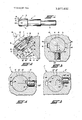
- FIG. 3 is a cross-section view on yet larger scale taken substantially along the line 33, FIG. 2;
- FIG. 4 is a cross-section view similar to FIG. 3 except showing the invention as applied to a cutter member having a single key disposed in a single keyway of the boring bar bore;
- FIG. 5 is a cross-section view similar to FIG. 4 illustrating yet another embodiment of the present invention.
- the boring bar 1 has at one end a shank 2 and the other end portion 3 has a bore 4 therethrough disposed at an angle with respect to the longitudinal axis of the boring bar 1.
- a counterbore 5 at one end of said bore 4 receives the ring member 6 of a boring bar insert assembly 7 which is removably retained in the boring bar 1 by a set screw 8, said insert assembly 7 preferably being of the type illustrated in Benjamin et al., US. Pat. No. 3,434,376 which comprises an adjusting dial member 9 having threaded engagement with the cutter member 10.
- the adjusting dial member 9 is resiliently seated against the conical seat 11 of the ring member 6 as by means of the Belleville spring 12, and as disclosed in said Benjamin et al., patent, the spring 12 is effective to take up play between the dial member 9 threads and the cutter member 10 threads by reason of the provision of the slots 14 in the intermediate portion of the dial member 9.
- the cutter member 10 has its radially inner shank portion 15 closely slidably fitted in the bore 4 and has keys 16 formed by the end portions of the cross pin 17 therein movable in keyways 18 in said bore 4 to prevent rotation of the cutter member 10 when the adjusting dial member 9 is rotated to move the cutter member 10 radially outwardly or inwardly.
- the cutter member 10 has cutting edges 19 which may be a part of the cutter member itself or which may be on an insert brazed on the cutter member 10 or which may be on a replaceable throwaway insert of tungsten carbide or the like removably clamped to the cutter member 10 as well known in the art (see for example the patent to Faber et al., US. Pat. No. 3,697,]87).
- the keys 16 instead of being the end portions of a cross pin 17 as herein illus trated may comprise a conventional square key in a key seat of the cutter member 10, a Woodruff key in a key seat in the cutter member 10, etc.
- the shank portion of the cutter member 10 is a close sliding fit in the boring bar bore 4 and such diameters may readily be held to close tolerances to provide such sliding fit while preserving interchangeability of insert assemblies 7 or cutter members 10 in different boring bar bores.
- keyways in bores are generally formed by broaching and hence to avoid need of holding extremely close tolerances with respect to key and keyway widths and locations the allowance may be 0.002 inch or more and hence with ordinary locking means the cutter member 10 may chatter when heavy cuts are made.
- the locking screw in the boring bar 1 as shown in FIG. 3 bears on an inclined flat 21 on the cutter member 10 at a point 23 which is eccentric of the cutter member axis to thereby impose a torque moment FD on the cutter member 10 to rotate the cutter member 10 in bore 4 to effect firm engagement of one side of at least one key 16 with the adjacent side of the keyway 18.
- the locking screw 20 be backed off only sufficiently to permit rotation of the dial member 9 while the key-keyway engagement is retained.
- FIG. 4 is a cross-section view similar to FIG. 3 except showing a lock screw 20 in association with a cutter member 10 and boring bar 1' having a single key 16' and keyway 18 and as apparent the lock screw 20' and inclined flat 21 may be located anywhere around the axis of the bore 4 and will yet impose a torque moment F'D' for firmly seating one side of the key 16 against the adjacent side of the keyway 18'.
- the lock screw 20 is located eccentrically of the axis of bore 4 and bears on one side of an axially elongated notch 24 in the cutter member 10 to impose a torque moment F"D on the latter for firmly seating one side of the key 16" against the adjacent side of the keyway 18".
- the point 23" coincides with the axis of the lock screw 20" but obviously the side of notch 24 may be inclined with respect to a flat end lock screw 20 or 20' as in FIGS. 1 to 4 to increase the moment arm D and to obtain axial drawing in action on the cutter member 10" and dial member 9".
- a boring bar having a bore with at least one longitudinal keyway; a cutter member having an outerportion with cutting edges thereon and an inner portion axially slidably fitted in said bore and having a key disposed in said keyway to prevent rotation of said cutter member; a ring-like adjusting dial member having threaded engagement with said cutter member and being secured to said bar for rotation about the axis of said bore while being restrained against axial movement whereby rotation of said dial member effects axial 1 adjusting movement of said cutter member; and lock screw means in said bar bearing on said cutter member to impose a torque force thereon to frictionally engage one side of said key with the adjacent side of said keyway; said cutter member inwardly of said dial member having a surface portion which is engaged by saidlock screw means eccentrically of the axis of said cutter member and bore.
- a boring bar having a bore with at least one longi- I tudinal keyway; a cutter member having an outer portion with cutting edges thereon and an inner portion axially slidably fitted in said bore and having a key disposed in said keyway to prevent rotation of said cutter member; a ring-like adjusting dial member having threaded engagement with said cutter member and I being secured to said bar for rotation aboutthe axis of said bore while being restrained against axial movement whereby rotation of said dial member effects axial adjusting movement of said cutter member; and lock screw means in said bar bearing on said cutter member lock screw means to effect frictional locking of said key I with said keyway further effects drawing of said cutter member axially inwardly to cause, through; the threaded engagement thereof with said dial member, frictional engagement of the latter with said bar further to lock said dial member against rotation 5.
- a tool assembly such as a boring bar wherein a cutter member is axially slidably keyed in a bore of said bar and wherein axial adjustment of said cutter member is effected by rotation of an axially retained adjusting dial member having threaded engagement with said cutter member
- lock screw means in said bar disposed transverse to said cut- I ter member to engage a side surface portion of the latter eccentrically of the axis of said dial member and said cutter member whereby said lock screw means is operative, when tightened, to impose a torque load on said cutter member to frictionally engage one. side of a key of said cutter member with a longitudinal keyway.
Landscapes
- Engineering & Computer Science (AREA)
- Mechanical Engineering (AREA)
- Drilling Tools (AREA)
- Cutting Tools, Boring Holders, And Turrets (AREA)
- Earth Drilling (AREA)
Abstract
A locking means for an adjustable boring bar insert of the type wherein the cutter element has a shank portion which is axially slidably keyed in a bore of the boring bar and is axially adjusted by a rotary, axially fixed dial member which has threaded engagement with said cutter element, said locking means being characterized in that it imposes a torque force on the cutter element which effects firm frictional locking engagement of one side of a cutter element key with the adjacent side of the keyway in the bore of the boring bar whereby in use of the boring bar-insert assembly the cutter element is solidly locked in precise adjusted position against chattering or like movements even during the making of heavy cuts to result in a precision boring operation. A further characterizing feature of the locking means herein is that the locking of the cutter element as aforesaid is effective to maintain firm frictional locking engagement of the adjusting dial member in engagement with a boring bar seat so that precision adjustment of the cutter element is maintained during use of the boring bar-insert assembly.
Description
United States Patent Benjamin [4 1 Apr. 15, 1975 LOCKING MEANS FOR ADJUSTABLE BORING BAR INSERTS AND THE LIKE [75] Inventor: Milton L. Benjamin, Chagrin Falls,
[52] US. Cl 408/155; 408/238 [51] Int. Cl B23b 29/02 [58] Field of Search 408/153, 154, 181, 155,
[56] References Cited UNITED STATES PATENTS 473,818 4/1892 Binns 403/362 X 2,537,517 l/1951 DeVlieg.. 408/153 2,669,890 2/1954 Tao 408/153 Primary Examiner--Andrew R. Juhasz Assistant Examiner-Z. R. Bilinsky Attorney, Agent, or FirmDonne1ly, Maky, Renner & Otto [57] I ABSTRACT A locking means for an adjustable boring bar insert of the type wherein the cutter element has a shank portion which is axially slidably keyed in a bore of the boring bar and is axially adjusted by a rotary, axially fixed dial member which has threaded engagement with said cutter element, said locking means being characterized in that it imposes a torque force on the cutter element which effects firm frictional locking engagement of one side of a cutter element key with the adjacent side of the keyway in the bore of the boring bar whereby in use of the boring bar-insert assembly the cutter element is solidly locked in precise adjusted position against chattering or like movements even during the making of heavy cuts to result in a precisionboring operation. A further characterizing feature of the locking means herein is that the locking of the cutter element as aforesaid is effective to maintain firm frictional locking engagement of the adjusting dial member in engagement with a boring bar seat so that precision adjustment of the cutter element is maintained during use of the boring bar-insert assembly.
6 Claims, 5 Drawing Figures LOCKING MEANS FOR ADJUSTABLE BORING BAR INSERTS AND THE LIKE BACKGROUND OF THE INVENTION It is old and well known to employ set screws to hold collars, sheaves, gears, etc., on shafts against rotational forces, the torsional holding power being substantially directly proportional to the seating torque in the case of cup, flat, and oval point set screws. In the case of cone and dog point set screws, they are usually spotted in holes in the shafts to provide increased torsional holding power developed by the shear strength across the cone point or dog point. When a set screw is used in combination with a key, the set screw diameter is generally made equal to the width of the key and in this combination the set screw is locating the parts in an axial direction with torsional load on the parts being carried by the key. It is also known to provide two or more set screws bearing on a shaft to provide increased torsional holding power with the set screws being radially disposed in axially aligned spaced relation or in circumferentially aligned, angularly spaced relation.
Aside from the foregoing well-known use of set screws for axially holding keyed parts together it is known from the following patents to provide a cutting tool member which is axially slidably keyed in a bore of a boring bar or like tool support member and which is adjusted by means of a rotary, axially fixed dial member having threaded engagement with the shank of the tool member: De Vlieg US. Pat. Nos. 2,330,692, De Vlieg 2,537,517, Yogus et al., 3,178,969, Winnen 3,198,079, Benjamin et al., 3,313,187, Cook 3,347,115, Holloway 3,349,648, and Benjamin et al., 3,434,376. For sake of economy of manufacture and for interchangeability of one tool member for another, the tool member key will have a width-wise clearance in the tool supporting member keyway and hence, after adjustment of the tool member by turning of the adjusting dial member, the tool member upon imposition of heavy cutting loads thereon may be subject to chattering or slight rotary movements as permitted by the key and keyway clearance aforesaid which may result in defects or inaccuracies in the bored hole of the workpiece.
In the afore-mentioned patents, the dial member is seated against the tool supporting member either by spring pressure or by locking screw means which draws the tool member, and thus the dial member, into frictional seating engagement with the tool supporting member. In the latter case, the precision adjustment of the tool member requires repeated manipulation of the locking screw means and adjusting dial member.
SUMMARY OF THE INVENTION In contradistinction to known ways of employing set screws to prevent rotation of a shaft-like member wherein the set screw acts along a line passing through the axis of the shaft or acts on the key of a keyed shaft to axially retain the shaft relative to the member being locked thereto, it is a principal object of this invention to provide a locking means for adjustable boring bar inserts and the like which is of simple form and highly effective to firmly lock the radially adjustable cutter member in precise adjusted position, the locking means herein being effective in conjunction with an axially slidably keyed member to impose a torque force on said member which firmly presses one side of the key against the adjacent side of the keyway thus to lock the member against any rotary movement regardless of widthwise clearance between the key and the keyway.
It is another object of this invention to provide a locking means of the character indicated which is further effective to retain the adjusting dial member in its seated position against a seat of the boring bar.
It is yet another object of this invention to provide a locking means of the character indicated which, in conjunction with application of a torque locking force on the cutter member as aforesaid, is additionally effective to impose an axial force on the cutter member to draw the adjusting dial member tightly against the boring bar seat to provide additional resistance to turning of the adjusting dial member except upon release of the locking means from locking engagement with the cutter member.
Other objects and advantages of the present invention will appear in the ensuing description.
BRIEF DESCRIPTION OF THE DRAWING FIG. 1 is an elevation view of a boring bar embodying the present locking means in conjunction with the adjustable insert in said bar;
FIG. 2 is a fragmentary diametrical cross-section view on enlarged scale in a plane passing through the axis of the boring bar bore along which the cutter member is axially adjustable;
FIG. 3 is a cross-section view on yet larger scale taken substantially along the line 33, FIG. 2;
FIG. 4 is a cross-section view similar to FIG. 3 except showing the invention as applied to a cutter member having a single key disposed in a single keyway of the boring bar bore; and
FIG. 5 is a cross-section view similar to FIG. 4 illustrating yet another embodiment of the present invention.
DETAIL DESCRIPTION OF THE PREFERRED EMBODIMENTS Referring first to FIGS. 1 and 2, the boring bar 1 has at one end a shank 2 and the other end portion 3 has a bore 4 therethrough disposed at an angle with respect to the longitudinal axis of the boring bar 1. A counterbore 5 at one end of said bore 4 receives the ring member 6 of a boring bar insert assembly 7 which is removably retained in the boring bar 1 by a set screw 8, said insert assembly 7 preferably being of the type illustrated in Benjamin et al., US. Pat. No. 3,434,376 which comprises an adjusting dial member 9 having threaded engagement with the cutter member 10. The adjusting dial member 9 is resiliently seated against the conical seat 11 of the ring member 6 as by means of the Belleville spring 12, and as disclosed in said Benjamin et al., patent, the spring 12 is effective to take up play between the dial member 9 threads and the cutter member 10 threads by reason of the provision of the slots 14 in the intermediate portion of the dial member 9.
The cutter member 10 has its radially inner shank portion 15 closely slidably fitted in the bore 4 and has keys 16 formed by the end portions of the cross pin 17 therein movable in keyways 18 in said bore 4 to prevent rotation of the cutter member 10 when the adjusting dial member 9 is rotated to move the cutter member 10 radially outwardly or inwardly. The cutter member 10 has cutting edges 19 which may be a part of the cutter member itself or which may be on an insert brazed on the cutter member 10 or which may be on a replaceable throwaway insert of tungsten carbide or the like removably clamped to the cutter member 10 as well known in the art (see for example the patent to Faber et al., US. Pat. No. 3,697,]87).
It is to be understood that the keys 16 instead of being the end portions of a cross pin 17 as herein illus trated may comprise a conventional square key in a key seat of the cutter member 10, a Woodruff key in a key seat in the cutter member 10, etc.
As aforesaid, the shank portion of the cutter member 10 is a close sliding fit in the boring bar bore 4 and such diameters may readily be held to close tolerances to provide such sliding fit while preserving interchangeability of insert assemblies 7 or cutter members 10 in different boring bar bores. However, keyways in bores are generally formed by broaching and hence to avoid need of holding extremely close tolerances with respect to key and keyway widths and locations the allowance may be 0.002 inch or more and hence with ordinary locking means the cutter member 10 may chatter when heavy cuts are made.
In order to securely lock the cutter member 10 in its adjusted position, the locking screw in the boring bar 1 as shown in FIG. 3 bears on an inclined flat 21 on the cutter member 10 at a point 23 which is eccentric of the cutter member axis to thereby impose a torque moment FD on the cutter member 10 to rotate the cutter member 10 in bore 4 to effect firm engagement of one side of at least one key 16 with the adjacent side of the keyway 18. When adjusting the cutter member 10 it is preferred that the locking screw 20 be backed off only sufficiently to permit rotation of the dial member 9 while the key-keyway engagement is retained. When the lock screw 20 tightening is in clockwise direction as viewed in FIGS. 1 and 3, it imposesan axial force at point 23 on the cutter member 10 to tend to more tightly draw the dial member 9 against the seat 11. In this way not only is the cutter member 10 securely locked in place as aforesaid, but also the adjusting dial member 9 is firmly locked in seated engage ment with the seat 11.
FIG. 4 is a cross-section view similar to FIG. 3 except showing a lock screw 20 in association with a cutter member 10 and boring bar 1' having a single key 16' and keyway 18 and as apparent the lock screw 20' and inclined flat 21 may be located anywhere around the axis of the bore 4 and will yet impose a torque moment F'D' for firmly seating one side of the key 16 against the adjacent side of the keyway 18'.
In FIG. 5 the lock screw 20 is located eccentrically of the axis of bore 4 and bears on one side of an axially elongated notch 24 in the cutter member 10 to impose a torque moment F"D on the latter for firmly seating one side of the key 16" against the adjacent side of the keyway 18". In this case, the point 23" coincides with the axis of the lock screw 20" but obviously the side of notch 24 may be inclined with respect to a flat end lock screw 20 or 20' as in FIGS. 1 to 4 to increase the moment arm D and to obtain axial drawing in action on the cutter member 10" and dial member 9".
The embodiments of the invention in which an exclusive property or privilege is claimed are defined as follows:
l. A boring bar having a bore with at least one longitudinal keyway; a cutter member having an outerportion with cutting edges thereon and an inner portion axially slidably fitted in said bore and having a key disposed in said keyway to prevent rotation of said cutter member; a ring-like adjusting dial member having threaded engagement with said cutter member and being secured to said bar for rotation about the axis of said bore while being restrained against axial movement whereby rotation of said dial member effects axial 1 adjusting movement of said cutter member; and lock screw means in said bar bearing on said cutter member to impose a torque force thereon to frictionally engage one side of said key with the adjacent side of said keyway; said cutter member inwardly of said dial member having a surface portion which is engaged by saidlock screw means eccentrically of the axis of said cutter member and bore.
2. The boring bar of claim 1 wherein the engagement 1 of said lock screw means with said surface portion is also eccentrically of the axis of said lock screw means.
so as to impose an axialinward force on said cutter member which through the threaded engagement thereof with said dial member frictionally locks the latter against said bar.
3. A boring bar having a bore with at least one longi- I tudinal keyway; a cutter member having an outer portion with cutting edges thereon and an inner portion axially slidably fitted in said bore and having a key disposed in said keyway to prevent rotation of said cutter member; a ring-like adjusting dial member having threaded engagement with said cutter member and I being secured to said bar for rotation aboutthe axis of said bore while being restrained against axial movement whereby rotation of said dial member effects axial adjusting movement of said cutter member; and lock screw means in said bar bearing on said cutter member lock screw means to effect frictional locking of said key I with said keyway further effects drawing of said cutter member axially inwardly to cause, through; the threaded engagement thereof with said dial member, frictional engagement of the latter with said bar further to lock said dial member against rotation 5. In a tool assembly such as a boring bar wherein a cutter member is axially slidably keyed in a bore of said bar and wherein axial adjustment of said cutter member is effected by rotation of an axially retained adjusting dial member having threaded engagement with said cutter member, the improvement which comprises lock screw means in said bar disposed transverse to said cut- I ter member to engage a side surface portion of the latter eccentrically of the axis of said dial member and said cutter member whereby said lock screw means is operative, when tightened, to impose a torque load on said cutter member to frictionally engage one. side of a key of said cutter member with a longitudinal keyway.
in said bore.
thereof except upon loosening of said lock screw means to release said dial member for rotation and to release the frictional engagement of said key with said keyway for consequent axial adjustment of said cutter member pursuant to rotation of said dial member.
l =l l l=
Claims (6)
1. A boring bar having a bore with at least one longitudinal keyway; a cutter member having an outer portion with cutting edges thereon and an inner portion axially slidably fitted in said bore and having a key disposed in said keyway to prevent rotation of said cutter meMber; a ring-like adjusting dial member having threaded engagement with said cutter member and being secured to said bar for rotation about the axis of said bore while being restrained against axial movement whereby rotation of said dial member effects axial adjusting movement of said cutter member; and lock screw means in said bar bearing on said cutter member to impose a torque force thereon to frictionally engage one side of said key with the adjacent side of said keyway; said cutter member inwardly of said dial member having a surface portion which is engaged by said lock screw means eccentrically of the axis of said cutter member and bore.
2. The boring bar of claim 1 wherein the engagement of said lock screw means with said surface portion is also eccentrically of the axis of said lock screw means so as to impose an axial inward force on said cutter member which through the threaded engagement thereof with said dial member frictionally locks the latter against said bar.
3. A boring bar having a bore with at least one longitudinal keyway; a cutter member having an outer portion with cutting edges thereon and an inner portion axially slidably fitted in said bore and having a key disposed in said keyway to prevent rotation of said cutter member; a ring-like adjusting dial member having threaded engagement with said cutter member and being secured to said bar for rotation about the axis of said bore while being restrained against axial movement whereby rotation of said dial member effects axial adjusting movement of said cutter member; and lock screw means in said bar bearing on said cutter member to impose a torque force thereon to frictionally engage one side of said key with the adjacent side of said keyway; said lock screw means being radially movable into engagement with the side of said cutter member at a point circumferentially spaced from said key thereof, said cutter member having a longitudinally extending flat thereon which is engaged by a portion of the radially inner end of said lock screw means which is radially spaced from the axis of said lock screw means.
4. The boring bar of claim 3 wherein turning of said lock screw means to effect frictional locking of said key with said keyway further effects drawing of said cutter member axially inwardly to cause, through the threaded engagement thereof with said dial member, frictional engagement of the latter with said bar further to lock said dial member against rotation.
5. In a tool assembly such as a boring bar wherein a cutter member is axially slidably keyed in a bore of said bar and wherein axial adjustment of said cutter member is effected by rotation of an axially retained adjusting dial member having threaded engagement with said cutter member, the improvement which comprises lock screw means in said bar disposed transverse to said cutter member to engage a side surface portion of the latter eccentrically of the axis of said dial member and said cutter member whereby said lock screw means is operative, when tightened, to impose a torque load on said cutter member to frictionally engage one side of a key of said cutter member with a longitudinal keyway in said bore.
6. The tool assembly of claim 5 wherein said lock screw means has an end surface radially spaced from the axis of said lock screw means thus engaged with said side surface portion whereby said lock screw means, when tightened, is further effective to tend to urge said cutter member axially to frictionally seat said dial member against said bar to prevent rotation thereof except upon loosening of said lock screw means to release said dial member for rotation and to release the frictional engagement of said key with said keyway for consequent axial adjustment of said cutter member pursuant to rotation of said dial member.
Priority Applications (5)
| Application Number | Priority Date | Filing Date | Title |
|---|---|---|---|
| US412203A US3877832A (en) | 1973-11-02 | 1973-11-02 | Locking means for adjustable boring bar inserts and the like |
| GB569474A GB1398376A (en) | 1973-11-02 | 1974-02-07 | Boring bars |
| CA192,321A CA992361A (en) | 1973-11-02 | 1974-02-12 | Locking means for adjustable boring bar inserts and the like |
| JP49017465A JPS5074872A (en) | 1973-11-02 | 1974-02-13 | |
| DE2409143A DE2409143C2 (en) | 1973-11-02 | 1974-02-26 | Boring bar |
Applications Claiming Priority (1)
| Application Number | Priority Date | Filing Date | Title |
|---|---|---|---|
| US412203A US3877832A (en) | 1973-11-02 | 1973-11-02 | Locking means for adjustable boring bar inserts and the like |
Publications (1)
| Publication Number | Publication Date |
|---|---|
| US3877832A true US3877832A (en) | 1975-04-15 |
Family
ID=23632022
Family Applications (1)
| Application Number | Title | Priority Date | Filing Date |
|---|---|---|---|
| US412203A Expired - Lifetime US3877832A (en) | 1973-11-02 | 1973-11-02 | Locking means for adjustable boring bar inserts and the like |
Country Status (5)
| Country | Link |
|---|---|
| US (1) | US3877832A (en) |
| JP (1) | JPS5074872A (en) |
| CA (1) | CA992361A (en) |
| DE (1) | DE2409143C2 (en) |
| GB (1) | GB1398376A (en) |
Cited By (10)
| Publication number | Priority date | Publication date | Assignee | Title |
|---|---|---|---|---|
| US4063842A (en) * | 1976-04-09 | 1977-12-20 | Kennametal Inc. | Adjustable boring bar |
| FR2496515A1 (en) * | 1980-12-22 | 1982-06-25 | Erickson Tool Co | |
| US4497601A (en) * | 1982-10-12 | 1985-02-05 | Multi Bar Systems Ltd. | Cutting tool |
| DE3614009A1 (en) * | 1985-04-29 | 1986-10-30 | GTE Valeron Corp., Danvers, Mass. | Adjustable tool-insert cartridge |
| US5040932A (en) * | 1989-12-04 | 1991-08-20 | Kennametal Inc. | Locator mechanism for a tool holder assembly |
| US5261302A (en) * | 1992-10-07 | 1993-11-16 | Kennametal Inc. | Quick-change tool holder with adjustment mechanism for repeatable center-height adjustment |
| US20050268759A1 (en) * | 2002-04-25 | 2005-12-08 | Cardemon Richard A | Slidable boring tool with fine adustment |
| US20060029476A1 (en) * | 2000-12-18 | 2006-02-09 | Cardemon Richard A | Adjustment method and apparatus for a boring tool |
| US7029209B2 (en) | 2000-12-18 | 2006-04-18 | Cardemon, Inc. | Slidable boring tool with fine adjustment |
| RU2399462C1 (en) * | 2009-04-06 | 2010-09-20 | Государственное образовательное учреждение высшего профессионального образования "Ярославский государственный технический университет" | Boring head |
Families Citing this family (3)
| Publication number | Priority date | Publication date | Assignee | Title |
|---|---|---|---|---|
| DE59003095D1 (en) * | 1989-08-18 | 1993-11-18 | Komet Stahlhalter Werkzeug | TOOL INSERT FOR CUTTING TOOLS. |
| DE4139650C2 (en) * | 1990-12-03 | 1995-03-30 | Romi Ind | Fine boring tool |
| DE4143449C2 (en) * | 1990-12-03 | 1995-08-31 | Romi Ind | Precision machine boring tool |
Citations (3)
| Publication number | Priority date | Publication date | Assignee | Title |
|---|---|---|---|---|
| US473818A (en) * | 1892-04-26 | William h | ||
| US2537517A (en) * | 1946-12-21 | 1951-01-09 | Vlieg Charles B De | Metal cutting tool |
| US2669890A (en) * | 1953-06-19 | 1954-02-23 | Portage Machine Co | Boring bar |
Family Cites Families (2)
| Publication number | Priority date | Publication date | Assignee | Title |
|---|---|---|---|---|
| US3434376A (en) * | 1967-04-03 | 1969-03-25 | Erickson Tool Co | Boring bar insert |
| DE1752012B1 (en) * | 1968-03-20 | 1971-08-05 | Breuning Robert | TOOL INSERT IN PARTICULAR FOR BORING BARS |
-
1973
- 1973-11-02 US US412203A patent/US3877832A/en not_active Expired - Lifetime
-
1974
- 1974-02-07 GB GB569474A patent/GB1398376A/en not_active Expired
- 1974-02-12 CA CA192,321A patent/CA992361A/en not_active Expired
- 1974-02-13 JP JP49017465A patent/JPS5074872A/ja active Pending
- 1974-02-26 DE DE2409143A patent/DE2409143C2/en not_active Expired
Patent Citations (3)
| Publication number | Priority date | Publication date | Assignee | Title |
|---|---|---|---|---|
| US473818A (en) * | 1892-04-26 | William h | ||
| US2537517A (en) * | 1946-12-21 | 1951-01-09 | Vlieg Charles B De | Metal cutting tool |
| US2669890A (en) * | 1953-06-19 | 1954-02-23 | Portage Machine Co | Boring bar |
Cited By (13)
| Publication number | Priority date | Publication date | Assignee | Title |
|---|---|---|---|---|
| US4063842A (en) * | 1976-04-09 | 1977-12-20 | Kennametal Inc. | Adjustable boring bar |
| FR2496515A1 (en) * | 1980-12-22 | 1982-06-25 | Erickson Tool Co | |
| US4396319A (en) * | 1980-12-22 | 1983-08-02 | Erickson Tool Company | Adjustable insert cartridge |
| US4497601A (en) * | 1982-10-12 | 1985-02-05 | Multi Bar Systems Ltd. | Cutting tool |
| DE3614009A1 (en) * | 1985-04-29 | 1986-10-30 | GTE Valeron Corp., Danvers, Mass. | Adjustable tool-insert cartridge |
| US5040932A (en) * | 1989-12-04 | 1991-08-20 | Kennametal Inc. | Locator mechanism for a tool holder assembly |
| US5261302A (en) * | 1992-10-07 | 1993-11-16 | Kennametal Inc. | Quick-change tool holder with adjustment mechanism for repeatable center-height adjustment |
| WO1994007637A1 (en) * | 1992-10-07 | 1994-04-14 | Kennametal Inc. | Quick-change tool holder with adjustment mechanism |
| US20060029476A1 (en) * | 2000-12-18 | 2006-02-09 | Cardemon Richard A | Adjustment method and apparatus for a boring tool |
| US7029209B2 (en) | 2000-12-18 | 2006-04-18 | Cardemon, Inc. | Slidable boring tool with fine adjustment |
| US7272877B2 (en) | 2000-12-18 | 2007-09-25 | Cardemon, Inc. | Adjustment method and apparatus for a boring tool |
| US20050268759A1 (en) * | 2002-04-25 | 2005-12-08 | Cardemon Richard A | Slidable boring tool with fine adustment |
| RU2399462C1 (en) * | 2009-04-06 | 2010-09-20 | Государственное образовательное учреждение высшего профессионального образования "Ярославский государственный технический университет" | Boring head |
Also Published As
| Publication number | Publication date |
|---|---|
| CA992361A (en) | 1976-07-06 |
| JPS5074872A (en) | 1975-06-19 |
| DE2409143A1 (en) | 1975-05-07 |
| GB1398376A (en) | 1975-06-18 |
| DE2409143C2 (en) | 1982-12-23 |
Similar Documents
| Publication | Publication Date | Title |
|---|---|---|
| US3877832A (en) | Locking means for adjustable boring bar inserts and the like | |
| US4353670A (en) | Machining tool | |
| JPH0790409B2 (en) | Machine rotation cutter such as countersink | |
| US2842233A (en) | Cutting blade lock | |
| DE102017104914B4 (en) | Stop for a drilling, milling or countersinking tool | |
| US3782848A (en) | Combination expandable cutting and seating tool | |
| CA2374223C (en) | Machining tool | |
| JP3356282B2 (en) | Milling tool shank | |
| US4129400A (en) | Trepanning tool | |
| US2308055A (en) | Adjustable countersink structure | |
| US4547997A (en) | Adjustable tool mount | |
| US4018542A (en) | Adjustable tool holder for boring bar | |
| US2284768A (en) | Cutting tool | |
| US3434376A (en) | Boring bar insert | |
| US5288182A (en) | Boring bar holder and insert with precision placement insert locator means | |
| US4340328A (en) | Rotary cutting tool and tool driver | |
| US3087360A (en) | Cutting tool having universal joint | |
| US4507027A (en) | Adjustable boring head tool holder | |
| US2643556A (en) | Boring tool | |
| US3239911A (en) | Bit holder | |
| US3724965A (en) | Double bladed cutting tool | |
| US3120961A (en) | Chucks | |
| US3762732A (en) | Clamping device or chuck | |
| US3767317A (en) | Double bladed cutting tool | |
| US3139800A (en) | Holder for milling cutters and like rotary tools |
Legal Events
| Date | Code | Title | Description |
|---|---|---|---|
| AS | Assignment |
Owner name: KENNAMETAL INC., P.O. BOX 231, LATROBE, PA 15650 Free format text: ASSIGNMENT OF ASSIGNORS INTEREST.;ASSIGNOR:ERICKSON TOOL COMPANY;REEL/FRAME:004985/0304 Effective date: 19881010 Owner name: KENNAMETAL INC., PENNSYLVANIA Free format text: ASSIGNMENT OF ASSIGNORS INTEREST;ASSIGNOR:ERICKSON TOOL COMPANY;REEL/FRAME:004985/0304 Effective date: 19881010 |