US3863729A - Engine compartment side shield structure - Google Patents
Engine compartment side shield structure Download PDFInfo
- Publication number
- US3863729A US3863729A US462587A US46258774A US3863729A US 3863729 A US3863729 A US 3863729A US 462587 A US462587 A US 462587A US 46258774 A US46258774 A US 46258774A US 3863729 A US3863729 A US 3863729A
- Authority
- US
- United States
- Prior art keywords
- door
- engine compartment
- side shield
- frame
- engine
- Prior art date
- Legal status (The legal status is an assumption and is not a legal conclusion. Google has not performed a legal analysis and makes no representation as to the accuracy of the status listed.)
- Expired - Lifetime
Links
Images


Classifications
-
- B—PERFORMING OPERATIONS; TRANSPORTING
- B62—LAND VEHICLES FOR TRAVELLING OTHERWISE THAN ON RAILS
- B62D—MOTOR VEHICLES; TRAILERS
- B62D25/00—Superstructure or monocoque structure sub-units; Parts or details thereof not otherwise provided for
- B62D25/08—Front or rear portions
- B62D25/10—Bonnets or lids, e.g. for trucks, tractors, busses, work vehicles
Definitions
- a pair of engine side shield structures are provided at [4 1 Feb. 4, 1975 the opposite sides of a vehicle engine and are supported on the frame of the vehicle.
- Each side shield structure includes a fixed baffle plate section, and upper and lower access doors which overlap the baffle section.
- the upper and lower doors are pivotally connected along lower edges thereof for swingable movement between respective closed positions wherein the panels are disposed vertically, one above the other, so as to block access to the inside of the engine compartment, and open positions wherein they are displaced angularly from their closed positions so as to permit access to the inside of the engine compartment.
- the present invention relates to an engine side shield structure and more particularly relates to a side shield structure of a type having an operator platform integral therewith andparticularly adaptable for use with relatively large vehicles such as industrial tractors or the like having engine compartments which are elevated a substantial distance above the ground thus necessitating the use of some sort of elevated support for an operator in order that he may perform routine servicing of an engine located in the compartment.
- One known industrial vehicle includes a fender which extends alongside and defines a compartment which is adjunct to the engine compartment. Access to the compartment in the fender is provided through means of a vertically swingable door forming a part of the fender and movable between a closed position wherein it blocks access to the compartment and an open position wherein it extends alongside the vehicle and permits access to the compartment.
- a step is integral with the door and is located in the compartment in the fender when the door isin its closed position and extends outwardly for use by the operator when the door is in its open position.
- a second door is provided for selectively blocking and permitting access to the engine compartment, the first and second doors cooperating to block access to both compartments when the doors are in the closed positions. Lock means are provided for securing the doors in their closed positions so as to prevent vandalism.
- a novel engine side shield assembly including first and second access or service doors and an operator support structure being integral with one of the doors, the doors being mounted for vertical swinging movement between respective closed positions blocking access to the interior of the engine compartment and respective open positions permitting access to the engine compartment.
- An object of the invention is to provide an engine side shield, as described in the preceding paragraph, which includes a baffle plate structure, the access doors being supported on the vehicle frame through means of the baffle structure.
- Another object of the invention is to provide a combined access door and operator support structure wherein the support structure includes a step and a platform so located that when the door is open the step extends outwardly from the vehicle frame and is disposed longitudinally from a ground wheel of the vehicle and the platform is located at a level above the step and extends between the frame and ground wheel.
- FIG. 2 is a rear elevational view of the tractor shown in FIG. 1;
- FIG. 3 is an enlarged right side elevational view of a portion of the tractor showing the right side shield structure and a part of the vehicle frame;
- FIG. 4 is a view taken along line 4-4 of FIG. 3 but showing only the right side portion of the tractor and showing the integral first access door and operator support in a dotted line open position;
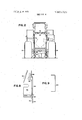
- FIG. 5 is a view taken along the line 5-5 of FIG. 3 but showing only the integral first access door and operator support structure;
- FIG. 6 is an enlarged view of the junction between the engine side shield structure and the vehicle frame
- FIG. 7 is a view taken along line-77 of FIG. 3 showing the first locking rod of the latch means for the second access door and its relationship to the first access door when the latter is closed;
- FIG. 8 is an enlarged sectional view taken along the line 8-8 of FIG. 3 showing one horizontal locking pin operable for releasably retaining the first access door in its operative position;
- FIG. 10 is an enlarged sectional view taken along the line 10-10 of FIG. 3 and showing a second one of the horizontal latching pins operable for securing the first access door in its operative position and further showing a safety latch retained in an aperture in the first access door through means of a padlock for preventing the first door from being opened.
- the engine side shield structure of the present invention may be applied to vehicles having various configurations, it is here applied to an articulated fourwheel drive loader indicated in its entirety by the reference numeral 10.
- the loader 10 includes front and rear sections 12 and 14, respectively, interconnected by a vertical pivot assembly 16, the front and rear sections respectively including front and rear frames 18 and 20 supported on front and rear pairs of wheels 22 and 24.
- an operator station 32 including a cab 34 in which is located a seat 36 for supporting an operator so that he can operate various controls located within his reach, one such control being a steering wheel 38 located forwardly of the seat.
- a plurality of vertically spaced steps 40 which lead to a horizontal platform 42 that extends alongside the cab 34 on a level even with the threshold of a door 44 of the cab to thus provide a support structure for an operator entering or leaving the cab 34.
- Forming part of the rear frame 20 andrespectively spaced vertically below the opposite sides of the hood 54 and bounding lower opposite side portions of the engine compartment 50 are right and left longitudinally extending channel members, only the right member being shown at 60.
- the right and left channel members are disposed such that their respective upper and lower flanges extend inwardly towards each other from respective outer planar surfaces, only the planar surface of the right channel member 60 being shown at 64.
- interconnecting the right and left channel members and bounding the lower portion of the engine compartment 50 is a bottom structure 68.
- a pair of rectangular openings are delineated at the opposite sides of the engine compartment 50 by respective lower edges of the opposite sides of the grill housing 52, by the upper flanges of the right and left channel members 60 and 62, by the reservoir 46 and by the grill housing 52, the respective openings being closed by right and left engine side shield structures 70 and 72 respectively supported by and extending vertically'above the right and left channel members 60 and 62.
- An engine 74 is supported on the rear frame 20 so as to be located in the engine compartment 50.
- Located in the grill housing 52 and coupled to the engine 74 in a conventional manner for being driven by the engine is a blower-type fan 76 to the rear of which is located a radiator 78.
- a blower-type fan 76 to the rear of which is located a radiator 78.
- radiator 78 associated with the engine 74 and located within the compartment 50 are various elements requiring periodic servicing such as oil and fuel filters, various oil and fuel system drain or bleed screws and various engine cooling system drain cocks such as those associated with the radiator and cylinder block.
- the engine shield structure 70 includes an access door and baffle plate support structure comprising an angled base plate 80 extending along in overlying relationship to the upper flange of the right channel member 60 and is secured thereto through means of a plurality of vertical bolts 82.
- Extending upwardly from and having lower ends secured in transverse relationship to the base plate 80 are a plurality of vertical support plates, a first of the plates being indicated by the reference numeral 84 and located adjacent the forward end of the side shield structure 70, a second of the plates being indicated by the reference numeral 86 and located adjacent the rear end of the side shield structure 70 and a third one of the plates being indicated by the reference numeral 88 and being in a location spaced a short distance forwardly from the rear support plate 86.
- an angled baffle plate 90 which is rectangular in side view and has upper and lower edges 92 and 94 located equidistant from and located inwardly from a horizontal longitudinally extending bend line 96.
- the upper portion of the side shield structure comprises a vertically disposed longitudinally extending rectangular upper access door 98 having a lower portion which overlaps an upper portion of the baffle plate such that the upper baffle plate edge 92 is located behind the access door 98, as viewed in FIG. 3.
- Three hinges 100 are secured to the access door 98 at longitudinally spaced locations along the bottom thereof, the first and second ones of the hinges being located adjacent the forward end and middle of the door and connected to a pair of support brackets 102 which are in turn secured to the baffle plate 90 while a third one of the hinges is located adjacent the rear end of the access door and is supported on a bracket 104 extending between and secured to the rear and intermediate support plates 86 and 88.
- the hinges 100 cooperate so as to define a horizontal longitudinally extending pivot axis about which the access door 98 is swingable between a closed position, as shown in the drawing, wherein it blocks access to the engine compartment 50 and an open position wherein it is rotated counterclockwise, as viewed in FIG. 4, from its closed position.
- the latch structures 106 and 108 respectively include latching elements in the form of latching rods 110 and 112.
- the latching rod 110 includes a vertically extending central portion 114 which is rotatably supported in upper and lower support brackets 116 and 118, respectively, fixed to the front support plate 84.
- the latching rod 110 further includes a transverse portion 120 which interconnects the upper end of the central portion 114 with a vertically extending upper end portion 122 of the rod.
- the access door 98 has a horizontal bracket 124 integral therewith and provided with a latch element receiving receptable 126 shaped and located for receiving the upper end portion 122 of the latching rod 110 when the latching rod is in its latched position as shown.
- the lower end of the latching rod 110 is bent rearwardly and then outwardly to form a handle 128 which may be grasped by the operator to rotate the latching rod between latched and unlatched positions.
- the rear latching rod 112 is constructed and mounted similarly to the forward rod 110.
- the latching rod 112 includes a vertical central portion 130 rotatably supported in upper and lower brackets 132 and 134, respectively, fixed to the rear support plate 86.
- the latching rod 112 further includes a transverse portion 136 which joins the upper end of the central portion 130 with a vertically extending upper end portion 138.
- a bracket 40 is secured to the inside of the access door 98 and is provided with a receptacle (not shown) similar to the receptacle 126 and having the upper end portion 138 of the latching rod 112 located therein when the latching rod is in a latched position as shown.
- a handle 142 is formed on the lower end of the latching rod 112 to provide means by which the rod may be manually turned.
- a bottom portion of the engine side shield structure 70 comprises a lower access door 144 which has a lower horizontal edge which extends adjacent the base plate 80 and which has an upper edge which is located above the lower edge 94 of the baffle plate 90 and extends parallel thereto between the front of the shield structure 70 and a location just forwardly of the intermediate support plate 88 at which location the upper edge is stepped vertically upwardly to a location just below the lower edge of the upper access door and from which the upper edge of the lower access door extends rearwardly to the end of the side shield structure 70.
- Three hinges 146 are secured at longitudinally spaced locations along the lower portion of the access door 144 and are connected to the base plate 80.
- the hinges 146 cooperate to define a horizontal fore-andaft extending pivot axis about which the lower access door 144 is swingable between a closed operative position, as illustrated, wherein the door prevents access to the engine compartment 50 and an open position, as shown in dotted lines in FIG. 4, wherein the door is displaced 180 counterclockwise from its closed position and permits access to the engine compartment.
- a coil compression spring 158 is received on the rod and has its rear end engaged with the rear ear of the mounting bracket 154 and has its forward end engaged with a washer 160 which is held in place by a cotter pin 162 extending through the pin 152. Forward movement of the latching pin 152 is limited by a cotter pin 164 which is disposed to engage the rear side of the mounting bracket 154 when the latching pin is in its latched position.
- the rear latch structure 150 includes a latching pin or rod 166 which extends oppositely from the latching pin 152 and is mounted for horizontal reciprocable movement in front and rear vertically disposed ears of a mounting bracket 168 secured to the inside of the lower access door 144.
- the latching pin 166 When the latching pin 166 is in a latched position as shown, the rearward end of the pin is received in an aperture or slot 170 formed in the intermediate vertical support plate 88.
- a coil compression spring 172 which is received on the pin and has its opposite ends engaged with the forward ear of the bracket 168 and a washer 174 held in place on the rod by a cotter pin 176.
- a second cotter pin 178 is provided in the latching pin 166 at a location wherein it abuts the forward side of the mounting bracket 168 to thus limit the rearward movement of the latchingpin.
- a safety latch structure 180 is also provided for maintaining the lower access door in its closed position.
- the safety latch structure 180 includes a strap-like latching element 182 which extends transversely alongside an upper rearwardly facing portion of the intermediate vertical support plate 88, the latching element 182 being pivotally connected at an intermediate location thereof to the support plate 88 through means of a horizontal longitudinally extending cap screw 184.
- the outer end portion of the latching element 182 extends through a vertically elongated rectangularaperture 186 located in the access door 144, the lower edge bounding the aperture being received in an upwardly opening notch or receptacle 188 located along the underside of the latching element 182.
- a security lock shown here as a padlock 190, which may be of a well-known key-operated or combination type, is releasably locked to an aperture provided in the outer end of the latching element 182, the padlock 190 being too large to pass through the aperture 186 thus necessitating its removal before the latching element 182 can be disengaged from the door 144 to permit the latter to be opened.
- the latching element 182 is biased to its latched position through means of a coil tension spring 192 having one end connected to the latching element 182 inwardly of the cap screw 184 and having its other end connected to a bracket 194 which is cantilever-supported from the hinge support bracket 104.
- the latch structure 180 prevents the door 144 from accidentally falling on the operator when the latching pins 152 and 166 are released.
- the notch 188 in the latching element 182 is made sufficiently large so as to permit the door 144 to be tilted out far enough to bring the latching pins 152 and 166 out of alignment with the respective apertures 156 and 170 so that the operator may remove both hands from the latching pins so that one hand can be used to operate the latch element 182 while the other is positioned to support the door 144 when it is released.
- the front and rear latch structures 106 and 108 for releasably retaining the upper access door 98 in its closed position will be located entirely within the engine compartment 50 and will thus be inaccessible from the exterior of the compartment.
- the lower access door 144 is in its closed position, it is disposed closely adjacent the respective ends of the handles 128 and 142 of the latching rods 110 and 112 so as to prevent the latch structures 106 and 108 from becoming accidentally unlatched.
- This relationship of the access door 144 to the handles can be best appreciated with reference to FIG. 7. Accordingly, once a padlock is installed in the latching element 182 of the safety latch structure 180, unauthorized opening of the engine compartment is prevented.
- An operator support structure is made as an integral part of the access door 144 so as to be located for supporting an operator when he is performing periodic servicing of components located within the engine compartment when the access doors 98 and 144 are open.
- the operator support structure includes a narrow elongate platform 196 which is formed as an integral leg of the access door 144 and is disposed so as to extend horizontally above the base plate 80, when the access door is in its closed position, between a location just rearwardly of the foremost of the hinges 146 and a location just forwardly of the intermediate vertical support plate 88.
- a plurality of gussets 198 are secured between the platform 196 and the inner wall of the door 144 to thereby provide support for the platform.
- a horizontal step 200 is secured to the inside of the lower access door 144 at a location between the rear and intermediate vertical support plates 86 and 88 and at a level above the platform 196.
- a pair of supports 202 are welded to the inside of the access door 144 and are respectively secured to the front and rear sides of the step to thus provide support therefor.
- the normally outer planar surface of the access door will be in engagement with the outer planar surface 64 of the right channel member 60 and the platform 196 and step 200 will extend outwardly from the channel member 60, the step 200 now being disposed at a level below that of the platform 196.
- a further step 204 is disposed so as to be located vertically below the step 200 when the access door is open.
- An operator then wishing to service components located within the engine compartment 50 would first step on the step 204 and from there go to the step 200 and then onto the platform 196 if desired.
- the steps 200 and 204 are located so as to be rearwardly of the rear pair of wheels 24, so as to be easily accessible to an operator, and that the platform 196 extends between the engine compartment 50 and the upper portion of the right wheel 24.
- the upper and lower access doors 98 and 144 by providing the upper and lower access doors 98 and 144, the movement of the access doors to their respective open positions is in no way hindered by the rear pair of wheels 24.
- the operation of the right side shield structure 70 is briefly summarized as-follows. Assuming that the upper and lower access doors 98 and 144 are in their closed positions as shown in FIGS. 3 and 4, unauthorized access to the engine compartment will be prevented since the padlock 190 will prevent the latching element 182 of the safety latch structure 180 from being disengaged from the lower access door 144 and with this door closed, the latching rods 110 and 112 cannot be manipulated to release the upper access door 198. Further, the lower access door 144 will prevent any accidental movement of the latch rod handle 128 and 140 in a direction for disengaging the respective upper end portions 110 and 112 from their respective receptacles.
- both portions of the doors 98 and 144 which overlap the baffle plate 90 will cooperate with the baffle plate to define paths for the passage of air and sound waves.
- the upper access door 98 will first be returned to its closed position and the latching rods 110 and 112 will be rotated to their respective latched positions. Next, the operator will grasp and retract the latching pins 152 and 166 and simultaneously swing the lower access door 144 to its closed position. Once the door is in place the pins are released and the springs 158 and 172 act to latch them. The element 182 will now be located in the aperture 186 and be engaged with the door 144. To secure the compartment 50, the padlock 190 is then installed.
- an industrial vehicle of a type including a longitudinal frame supported on rotatable ground-engaging means, an engine mounted on the frame and located in an engine compartment bounded at top and upper side portions by a hood, at bottom and lower side portions by said frame and at opposite intermediate side portions by a pair of side shield structures extending between said frame and said hood, the improvement comprising: at least one of the side shield structures including a longitudinal upright door support means fixed to said frame and extending upwardly alongside said engine between the frame and hood; said support means including a baffle plate having upper and lower horizontal longitudinally extending edges respectively spaced below and above said hood and frame and inwardly from a bend line located substantially halfway between and extending parallel to said upper and lower edges; a first longitudinal door normally located in a closed position wherein it is vertically disposed beside and outwardly of a lower portion of said baffle plate and cooperate therewith to form a downwardly and inwardly directed passage leading to the engine compartment, said first door being pivotally mounted, adjacent to lower edge thereof, to said door support
- said ground-engaging means includes upwardly extending inner surface means located beside and spaced outwardly from only a part of the one side shield structure, as considered in the longitudinal dimension of the latter; said first door extending substantially the entire length of the one side shield structure, as considered in the longitudinal dimension of the latter; and including a first and second longitudinally adjacent portions respectively extending coextensive with and being longitudinally displaced from the inner surface means of said ground-engaging means; said first and second portions respectively having heights, as considered with the first door in its closed position, which are less than and greater than the distance that the inner surface means is spaced from the one side shield structure and an operator support structure being integral with the first door and including a first and second support means respectively integral with said first and second portions of said first door and disposed so as to be located within said engine compartment when the first door is closed and so as to project outwardly horizonfirst plate overlaps said first end of the baffle plate.
Abstract
A pair of engine side shield structures are provided at the opposite sides of a vehicle engine and are supported on the frame of the vehicle. Each side shield structure includes a fixed baffle plate section, and upper and lower access doors which overlap the baffle section. The upper and lower doors are pivotally connected along lower edges thereof for swingable movement between respective closed positions wherein the panels are disposed vertically, one above the other, so as to block access to the inside of the engine compartment, and open positions wherein they are displaced angularly from their closed positions so as to permit access to the inside of the engine compartment. Integral with the lower door is an operator support structure which is located in the engine compartment when the lower door is in its closed position and which is located alongside the vehicle frame and projects outwardly therefrom to provide an operator support when the lower door is in its open position. Associated with the first door is a latch mechanism which can be padlocked in place so as to prevent unauthorized opening of the engine compartment, a further latch mechanism being associated with the second door and located such that it is entirely inside the engine compartment when the upper and lower doors are in their closed positions. A third latch mechanism is associated with the lower door and must be released before the first door can be opened to provide access to the latch mechanism associated with the second door.
Description
United States Patent [191 Von Fummetti et al.
[ ENGINE COMPARTMENT SIDE SHIELD STRUCTURE [75] Inventors: Cy William Von Fummetti; David Dennis Latham, both of Dubuque, Iowa [73] Assignee: Deere & Company, Moline, Ill.
[22] Filed: Apr. 19, 1974 211 Appl. No.: 462,587
[52] US. Cl. 180/69 R, 180/89 R, 280/164 R [51] Int. Cl B6211 25/10 [58] Field of Search 180/69 R, 89 R; 280/163,
280/164 R, 166; 292/DIG. 23
Primary Examiner-David Schonberg Assistant Examiner-Terrance L. Siemens [5 7] ABSTRACT I A pair of engine side shield structures are provided at [4 1 Feb. 4, 1975 the opposite sides of a vehicle engine and are supported on the frame of the vehicle. Each side shield structure includes a fixed baffle plate section, and upper and lower access doors which overlap the baffle section. The upper and lower doors are pivotally connected along lower edges thereof for swingable movement between respective closed positions wherein the panels are disposed vertically, one above the other, so as to block access to the inside of the engine compartment, and open positions wherein they are displaced angularly from their closed positions so as to permit access to the inside of the engine compartment. lntegral with the lower door is an operator support structure which is located in the engine compartment when the lower door is in its closed position and which is located alongside the vehicle frame and projects outwardly therefrom to provide an operator support when the lower door is in its open position. Associated with the first door is a latch mechanism which can be padlocked in place so as to prevent unauthorized opening of the engine compartment, a further latch mechanism being associated with the second door and located such that it is entirely inside the engine compartment when the upper and lower doors are in their closed positions. A third latch mechanism is associated with the lower door and must be released before the first door can be opened to provide access to the latch mechanism associated with the second door.
3 Claims, 10 Drawing Figures PATENTED FEB 41975 SHEET 10F 4 NON I PATEN TED FEB 4 5 SHEET 2 BF 4 FIG 9 BACKGROUND OF THE INVENTION The present invention relates to an engine side shield structure and more particularly relates to a side shield structure of a type having an operator platform integral therewith andparticularly adaptable for use with relatively large vehicles such as industrial tractors or the like having engine compartments which are elevated a substantial distance above the ground thus necessitating the use of some sort of elevated support for an operator in order that he may perform routine servicing of an engine located in the compartment.
One known industrial vehicle includes a fender which extends alongside and defines a compartment which is adjunct to the engine compartment. Access to the compartment in the fender is provided through means of a vertically swingable door forming a part of the fender and movable between a closed position wherein it blocks access to the compartment and an open position wherein it extends alongside the vehicle and permits access to the compartment. A step is integral with the door and is located in the compartment in the fender when the door isin its closed position and extends outwardly for use by the operator when the door is in its open position. A second door is provided for selectively blocking and permitting access to the engine compartment, the first and second doors cooperating to block access to both compartments when the doors are in the closed positions. Lock means are provided for securing the doors in their closed positions so as to prevent vandalism.
SUMMARY OF THE INVENTION According to the present invention, there is provided a novel engine side shield assembly including first and second access or service doors and an operator support structure being integral with one of the doors, the doors being mounted for vertical swinging movement between respective closed positions blocking access to the interior of the engine compartment and respective open positions permitting access to the engine compartment.
An object of the invention is to provide an engine side shield, as described in the preceding paragraph, which includes a baffle plate structure, the access doors being supported on the vehicle frame through means of the baffle structure.
Another object of the invention is to provide a combined access door and operator support structure wherein the support structure includes a step and a platform so located that when the door is open the step extends outwardly from the vehicle frame and is disposed longitudinally from a ground wheel of the vehicle and the platform is located at a level above the step and extends between the frame and ground wheel.
These and other objects will become apparent from reading the following description in conjunction with the appended drawings.
BRIEF DESCRIPTION OF THE DRAWINGS FIG. 2 is a rear elevational view of the tractor shown in FIG. 1;
FIG. 3 is an enlarged right side elevational view of a portion of the tractor showing the right side shield structure and a part of the vehicle frame;
FIG. 4 is a view taken along line 4-4 of FIG. 3 but showing only the right side portion of the tractor and showing the integral first access door and operator support in a dotted line open position;
FIG. 5 is a view taken along the line 5-5 of FIG. 3 but showing only the integral first access door and operator support structure;
FIG. 6 is an enlarged view of the junction between the engine side shield structure and the vehicle frame,
as shown in FIG. 4;
FIG. 7 is a view taken along line-77 of FIG. 3 showing the first locking rod of the latch means for the second access door and its relationship to the first access door when the latter is closed;
FIG. 8 is an enlarged sectional view taken along the line 8-8 of FIG. 3 showing one horizontal locking pin operable for releasably retaining the first access door in its operative position;
FIG. 9 is a top plan view of the bracket shown in FIG. 8 for supporting the latching pin;
FIG. 10 is an enlarged sectional view taken along the line 10-10 of FIG. 3 and showing a second one of the horizontal latching pins operable for securing the first access door in its operative position and further showing a safety latch retained in an aperture in the first access door through means of a padlock for preventing the first door from being opened.
DESCRIPTION OF THE PREFERRED EMBODIMENT While the engine side shield structure of the present invention may be applied to vehicles having various configurations, it is here applied to an articulated fourwheel drive loader indicated in its entirety by the reference numeral 10. The loader 10 includes front and rear sections 12 and 14, respectively, interconnected by a vertical pivot assembly 16, the front and rear sections respectively including front and rear frames 18 and 20 supported on front and rear pairs of wheels 22 and 24.
A support arm structure 26 extends forwardly from and has its rear end pivotally connected to the front frame 18, as is conventional, for permitting vertical movement of the arm structure 26. A bucket 28 is pivotally connected to the forward ends of the arm structure 26 in a conventional manner for permitting tilting movement of the bucket and a power-operated tilt linkage 30 is connected between the frame 18 and the bucket 28 for accomplishing tilting of the bucket.
Mounted on the rear vehicle section 14 just rearwardly of the front section 12 is an operator station 32 including a cab 34 in which is located a seat 36 for supporting an operator so that he can operate various controls located within his reach, one such control being a steering wheel 38 located forwardly of the seat. Supported so as to extend outwardly from the right side of the rear frame 20 are a plurality of vertically spaced steps 40 which lead to a horizontal platform 42 that extends alongside the cab 34 on a level even with the threshold of a door 44 of the cab to thus provide a support structure for an operator entering or leaving the cab 34.
A box-shaped reservoir 46 is mounted on the frame 20 just rearwardly of the cab 34 and includes a vertical rear wall 48 which bounds the forward end of an engine compartment 50. A grill housing 52 is mounted on the rear end of the frame 20 and bounds the rear end of the engine compartment 50. The top and upper side portions of the engine compartment 50 are bounded by a hood 54 which extends longitudinally between the reservoir 46 and the grill housing 52 and has its forward and rearward ends respectively supported on flanges 56 and 58, respectively, that are integral with the reservoir wall 48 and the grill housing 52. Forming part of the rear frame 20 andrespectively spaced vertically below the opposite sides of the hood 54 and bounding lower opposite side portions of the engine compartment 50 are right and left longitudinally extending channel members, only the right member being shown at 60. The right and left channel members are disposed such that their respective upper and lower flanges extend inwardly towards each other from respective outer planar surfaces, only the planar surface of the right channel member 60 being shown at 64. interconnecting the right and left channel members and bounding the lower portion of the engine compartment 50 is a bottom structure 68. A pair of rectangular openings are delineated at the opposite sides of the engine compartment 50 by respective lower edges of the opposite sides of the grill housing 52, by the upper flanges of the right and left channel members 60 and 62, by the reservoir 46 and by the grill housing 52, the respective openings being closed by right and left engine side shield structures 70 and 72 respectively supported by and extending vertically'above the right and left channel members 60 and 62.
An engine 74 is supported on the rear frame 20 so as to be located in the engine compartment 50. Located in the grill housing 52 and coupled to the engine 74 in a conventional manner for being driven by the engine is a blower-type fan 76 to the rear of which is located a radiator 78. It is to be understood that associated with the engine 74 and located within the compartment 50 are various elements requiring periodic servicing such as oil and fuel filters, various oil and fuel system drain or bleed screws and various engine cooling system drain cocks such as those associated with the radiator and cylinder block.
Except for the fact that they are constructed so as to be respectively used on the right and left sides of the loader 10, the right and left side shield structures 70 and 72 are identical. For the sake of brevity, only the right side shield structure assembly is described in detail. The engine shield structure 70 includes an access door and baffle plate support structure comprising an angled base plate 80 extending along in overlying relationship to the upper flange of the right channel member 60 and is secured thereto through means of a plurality of vertical bolts 82. Extending upwardly from and having lower ends secured in transverse relationship to the base plate 80 are a plurality of vertical support plates, a first of the plates being indicated by the reference numeral 84 and located adjacent the forward end of the side shield structure 70, a second of the plates being indicated by the reference numeral 86 and located adjacent the rear end of the side shield structure 70 and a third one of the plates being indicated by the reference numeral 88 and being in a location spaced a short distance forwardly from the rear support plate 86.
Extending longitudinally between the front and intermediate support plates 84 and 86 and having its front and rear ends respectively secured thereto is an angled baffle plate 90 which is rectangular in side view and has upper and lower edges 92 and 94 located equidistant from and located inwardly from a horizontal longitudinally extending bend line 96. The upper portion of the side shield structure comprises a vertically disposed longitudinally extending rectangular upper access door 98 having a lower portion which overlaps an upper portion of the baffle plate such that the upper baffle plate edge 92 is located behind the access door 98, as viewed in FIG. 3. Three hinges 100 are secured to the access door 98 at longitudinally spaced locations along the bottom thereof, the first and second ones of the hinges being located adjacent the forward end and middle of the door and connected to a pair of support brackets 102 which are in turn secured to the baffle plate 90 while a third one of the hinges is located adjacent the rear end of the access door and is supported on a bracket 104 extending between and secured to the rear and intermediate support plates 86 and 88. The hinges 100 cooperate so as to define a horizontal longitudinally extending pivot axis about which the access door 98 is swingable between a closed position, as shown in the drawing, wherein it blocks access to the engine compartment 50 and an open position wherein it is rotated counterclockwise, as viewed in FIG. 4, from its closed position.
For the purpose of releasably latching the upper access door 98 in its closed position, there is provided similarly constructed front and rear latch structures 106 and 108. The latch structures 106 and 108 respectively include latching elements in the form of latching rods 110 and 112. The latching rod 110 includes a vertically extending central portion 114 which is rotatably supported in upper and lower support brackets 116 and 118, respectively, fixed to the front support plate 84. The latching rod 110 further includes a transverse portion 120 which interconnects the upper end of the central portion 114 with a vertically extending upper end portion 122 of the rod. Thus, it will be appreciated that, when the rod 110 is rotated about the longitudinal axis of the central portion 114, the upper end portion 122 will trace out an arcuate path. As can best be seen in FIG. 7, the access door 98 has a horizontal bracket 124 integral therewith and provided with a latch element receiving receptable 126 shaped and located for receiving the upper end portion 122 of the latching rod 110 when the latching rod is in its latched position as shown. As viewed in FIG. 7, the lower end of the latching rod 110 is bent rearwardly and then outwardly to form a handle 128 which may be grasped by the operator to rotate the latching rod between latched and unlatched positions.
The rear latching rod 112 is constructed and mounted similarly to the forward rod 110. Thus, the latching rod 112 includes a vertical central portion 130 rotatably supported in upper and lower brackets 132 and 134, respectively, fixed to the rear support plate 86. The latching rod 112 further includes a transverse portion 136 which joins the upper end of the central portion 130 with a vertically extending upper end portion 138. A bracket 40 is secured to the inside of the access door 98 and is provided with a receptacle (not shown) similar to the receptacle 126 and having the upper end portion 138 of the latching rod 112 located therein when the latching rod is in a latched position as shown. A handle 142 is formed on the lower end of the latching rod 112 to provide means by which the rod may be manually turned.
A bottom portion of the engine side shield structure 70 comprises a lower access door 144 which has a lower horizontal edge which extends adjacent the base plate 80 and which has an upper edge which is located above the lower edge 94 of the baffle plate 90 and extends parallel thereto between the front of the shield structure 70 and a location just forwardly of the intermediate support plate 88 at which location the upper edge is stepped vertically upwardly to a location just below the lower edge of the upper access door and from which the upper edge of the lower access door extends rearwardly to the end of the side shield structure 70. Three hinges 146 are secured at longitudinally spaced locations along the lower portion of the access door 144 and are connected to the base plate 80. The hinges 146 cooperate to define a horizontal fore-andaft extending pivot axis about which the lower access door 144 is swingable between a closed operative position, as illustrated, wherein the door prevents access to the engine compartment 50 and an open position, as shown in dotted lines in FIG. 4, wherein the door is displaced 180 counterclockwise from its closed position and permits access to the engine compartment.
Provided for the purpose of releasably latching the lower access door 144 in its closed position are substantially identical front and rear latch structures 148 and 150, respectively, which are located centrally between the front and intermediate vertical support plates 84 and 88. As can best be seen in FIGS. 3, 8 and 9, the front latch structure 148 includes a horizontally disposed latching pin or rod 152 reciprocally mounted in front and rear vertically disposed ears of a mounting bracket 154 which is secured to the inside of the access door 144. When thelatching pin 152 is in a latched condition as shown, the forward end of the pin 152 is located within an aperture or slot 156 located in the front vertical support plate 84. For the purpose of biasing the latching pin to its latched position, a coil compression spring 158 is received on the rod and has its rear end engaged with the rear ear of the mounting bracket 154 and has its forward end engaged with a washer 160 which is held in place by a cotter pin 162 extending through the pin 152. Forward movement of the latching pin 152 is limited by a cotter pin 164 which is disposed to engage the rear side of the mounting bracket 154 when the latching pin is in its latched position. The rear latch structure 150 includes a latching pin or rod 166 which extends oppositely from the latching pin 152 and is mounted for horizontal reciprocable movement in front and rear vertically disposed ears of a mounting bracket 168 secured to the inside of the lower access door 144. When the latching pin 166 is in a latched position as shown, the rearward end of the pin is received in an aperture or slot 170 formed in the intermediate vertical support plate 88. For the purpose of biasing the pin 166 to its latched position, there is provided a coil compression spring 172 which is received on the pin and has its opposite ends engaged with the forward ear of the bracket 168 and a washer 174 held in place on the rod by a cotter pin 176. A second cotter pin 178 is provided in the latching pin 166 at a location wherein it abuts the forward side of the mounting bracket 168 to thus limit the rearward movement of the latchingpin.
For preventing unauthorized entry into the engine compartment 50, a safety latch structure 180 is also provided for maintaining the lower access door in its closed position. The safety latch structure 180 includes a strap-like latching element 182 which extends transversely alongside an upper rearwardly facing portion of the intermediate vertical support plate 88, the latching element 182 being pivotally connected at an intermediate location thereof to the support plate 88 through means of a horizontal longitudinally extending cap screw 184. The outer end portion of the latching element 182 extends through a vertically elongated rectangularaperture 186 located in the access door 144, the lower edge bounding the aperture being received in an upwardly opening notch or receptacle 188 located along the underside of the latching element 182. A security lock, shown here as a padlock 190, which may be of a well-known key-operated or combination type, is releasably locked to an aperture provided in the outer end of the latching element 182, the padlock 190 being too large to pass through the aperture 186 thus necessitating its removal before the latching element 182 can be disengaged from the door 144 to permit the latter to be opened. The latching element 182 is biased to its latched position through means of a coil tension spring 192 having one end connected to the latching element 182 inwardly of the cap screw 184 and having its other end connected to a bracket 194 which is cantilever-supported from the hinge support bracket 104.
in addition to preventing unauthorized access to the engine compartment 50, the latch structure 180 prevents the door 144 from accidentally falling on the operator when the latching pins 152 and 166 are released. To carry out this operation, the notch 188 in the latching element 182 is made sufficiently large so as to permit the door 144 to be tilted out far enough to bring the latching pins 152 and 166 out of alignment with the respective apertures 156 and 170 so that the operator may remove both hands from the latching pins so that one hand can be used to operate the latch element 182 while the other is positioned to support the door 144 when it is released.
Thus, it will be appreciated that when both the upper access door 98 and the lower access door 144 are in their respective closed positions, the front and rear latch structures 106 and 108 for releasably retaining the upper access door 98 in its closed position will be located entirely within the engine compartment 50 and will thus be inaccessible from the exterior of the compartment. Further, when the lower access door 144 is in its closed position, it is disposed closely adjacent the respective ends of the handles 128 and 142 of the latching rods 110 and 112 so as to prevent the latch structures 106 and 108 from becoming accidentally unlatched. This relationship of the access door 144 to the handles can be best appreciated with reference to FIG. 7. Accordingly, once a padlock is installed in the latching element 182 of the safety latch structure 180, unauthorized opening of the engine compartment is prevented.
An operator support structure is made as an integral part of the access door 144 so as to be located for supporting an operator when he is performing periodic servicing of components located within the engine compartment when the access doors 98 and 144 are open. Thus, the operator support structure includes a narrow elongate platform 196 which is formed as an integral leg of the access door 144 and is disposed so as to extend horizontally above the base plate 80, when the access door is in its closed position, between a location just rearwardly of the foremost of the hinges 146 and a location just forwardly of the intermediate vertical support plate 88. A plurality of gussets 198 are secured between the platform 196 and the inner wall of the door 144 to thereby provide support for the platform. A horizontal step 200 is secured to the inside of the lower access door 144 at a location between the rear and intermediate vertical support plates 86 and 88 and at a level above the platform 196. A pair of supports 202 are welded to the inside of the access door 144 and are respectively secured to the front and rear sides of the step to thus provide support therefor. As can best be seen in FIG. 4, when the lower access door 144 is moved to its dotted line open position, the normally outer planar surface of the access door will be in engagement with the outer planar surface 64 of the right channel member 60 and the platform 196 and step 200 will extend outwardly from the channel member 60, the step 200 now being disposed at a level below that of the platform 196. As can be seen in FIG. 1, a further step 204 is disposed so as to be located vertically below the step 200 when the access door is open. An operator then wishing to service components located within the engine compartment 50 would first step on the step 204 and from there go to the step 200 and then onto the platform 196 if desired. It is here to be noted that the steps 200 and 204 are located so as to be rearwardly of the rear pair of wheels 24, so as to be easily accessible to an operator, and that the platform 196 extends between the engine compartment 50 and the upper portion of the right wheel 24. Further, it is to be noted that by providing the upper and lower access doors 98 and 144, the movement of the access doors to their respective open positions is in no way hindered by the rear pair of wheels 24.
The operation of the right side shield structure 70 is briefly summarized as-follows. Assuming that the upper and lower access doors 98 and 144 are in their closed positions as shown in FIGS. 3 and 4, unauthorized access to the engine compartment will be prevented since the padlock 190 will prevent the latching element 182 of the safety latch structure 180 from being disengaged from the lower access door 144 and with this door closed, the latching rods 110 and 112 cannot be manipulated to release the upper access door 198. Further, the lower access door 144 will prevent any accidental movement of the latch rod handle 128 and 140 in a direction for disengaging the respective upper end portions 110 and 112 from their respective receptacles.
Further, with the doors in their closed positions, both portions of the doors 98 and 144 which overlap the baffle plate 90 will cooperate with the baffle plate to define paths for the passage of air and sound waves.
Should the operator desire to perform service on any of the components located within the engine compartment 50, he will first remove the padlock 190 from the latching element 182. His next step will be to simultaneously manipulate the horizontally arranged latching pins or rods 152 and 166 so as to respectively disengage them from the apertures 156 and 170. The operator will then tilt the upper end of the lower access door 144 outwardly to the extent permitted by the notch 188 in the lower side of the latching element 182. At this time the ends of the latching pins 152 and 166 should be disposed out of alignment with respective apertures 156 and 170 and the operator may then release the latching pins. He will next raise up on the outer end of the latching element 182 to disengage it from the access door 144 and the latter will then be swung to its open-line position as shown in FIG. 4. The step 200 and the platform 196 will now be exposed and the operator may support himself thereon for subsequent steps of the operation. If it is required that the upper access door 98 be swung to its open position in order for the operator to perform the necessary service, he will grab one of the handles of the latching rods 110 and 112 and pull on the same to cause the upper end of the rod to be disengaged from the associated receptacle. The operator will then similarly manipulate the other latching rod with one hand while having the other free to lower the access door 98.
Once the operator has performed the necessary service, the upper access door 98 will first be returned to its closed position and the latching rods 110 and 112 will be rotated to their respective latched positions. Next, the operator will grasp and retract the latching pins 152 and 166 and simultaneously swing the lower access door 144 to its closed position. Once the door is in place the pins are released and the springs 158 and 172 act to latch them. The element 182 will now be located in the aperture 186 and be engaged with the door 144. To secure the compartment 50, the padlock 190 is then installed.
We claim:
1. In an industrial vehicle of a type including a longitudinal frame supported on rotatable ground-engaging means, an engine mounted on the frame and located in an engine compartment bounded at top and upper side portions by a hood, at bottom and lower side portions by said frame and at opposite intermediate side portions by a pair of side shield structures extending between said frame and said hood, the improvement comprising: at least one of the side shield structures including a longitudinal upright door support means fixed to said frame and extending upwardly alongside said engine between the frame and hood; said support means including a baffle plate having upper and lower horizontal longitudinally extending edges respectively spaced below and above said hood and frame and inwardly from a bend line located substantially halfway between and extending parallel to said upper and lower edges; a first longitudinal door normally located in a closed position wherein it is vertically disposed beside and outwardly of a lower portion of said baffle plate and cooperate therewith to form a downwardly and inwardly directed passage leading to the engine compartment, said first door being pivotally mounted, adjacent to lower edge thereof, to said door support means for vertical swinging movement about a first horizontal, longitudinal axis from said closed position to an open position; a second longitudinal door normally located in a closed position wherein it is vertically disposed beside and outwardly of an upper portion of said baffle plate including said upper edge and cooperates therewith to define an upwardly and inwardly directed passage leading to the engine compartment; and said second door being pivotally mounted, adjacent a lower edge thereof, to said door support means for vertical swinging movement about a second horizontal, longitudinal axis from said closed position to an open position; latching means for releasably latching said first and second doors in their closed positions; and said first and second doors cooperating with said baffle plate to block manual access to the compartment when said doors are in their closed positions.
2. The industrial vehicle defined in claim 1 wherein said ground-engaging means includes upwardly extending inner surface means located beside and spaced outwardly from only a part of the one side shield structure, as considered in the longitudinal dimension of the latter; said first door extending substantially the entire length of the one side shield structure, as considered in the longitudinal dimension of the latter; and including a first and second longitudinally adjacent portions respectively extending coextensive with and being longitudinally displaced from the inner surface means of said ground-engaging means; said first and second portions respectively having heights, as considered with the first door in its closed position, which are less than and greater than the distance that the inner surface means is spaced from the one side shield structure and an operator support structure being integral with the first door and including a first and second support means respectively integral with said first and second portions of said first door and disposed so as to be located within said engine compartment when the first door is closed and so as to project outwardly horizonfirst plate overlaps said first end of the baffle plate.
UNITED STATES PATENT OFFICE CERTIFICATE OF CORRECTION Patent No. 3, 863,729 Dated 4 February 1975 Cy William Von F etti; David Dennis Latham I It is certified that error appears in the above-identified patent and that said Letters Patent are hereby corrected as shown below:
Cover Sheet, [75] Inventors: change "Cy" to --Cyril--, and change "Fummetti" to -Fumetti-;
Column 8, line 54, change "cooperate" to -cooperates--;
Colume 8, line 57, change "to" (first occurence) to (SEAL) Attest:
C. MARSHALL DANN Commissioner of Patents and Trademarks RUTH C. MASON Attesting Officer ORM PO-1050 (10-69) USCOMM-DC GOS'IS-PBQ a uis. GOVERNMENT PRINTING ornc: 1 I969 o-ass-su.
Claims (3)
1. In an industrial vehicle of a type including a longitudinal frame supported on rotatable ground-engaging means, an engine mounted on the frame and located in an engine compartment bounded at top and upper side portions by a hood, at bottom and lower side portions by said frame and at opposite intermediate side portions by a pair of side shield structures extending between said frame and said hood, the improvement comprising: at least one of the side shield structures including a longitudinal upright door support means fixed to said frame and extending upwardly alongside said engine between the frame and hood; said support means including a baffle plate having upper and lower horizontal longitudinally extending edges respectively spaced below and above said hood and frame and inwardly from a bend line located substantially halfway between and extending parallel to said upper and lower edges; a first longitudinal door normally located in a closed position wherein it is vertically disposed beside and outwardly of a lower portion of said baffle plate and cooperate therewith to form a downwardly and inwardly directed passage leading to the engine compartment, said first door being pivotally mounted, adjacent to lower edge thereof, to said door support means for vertical swinging movement about a first horizontal, longitudinal axis from said closed position to an open position; a second longitudinal door normally located in a closed position wherein it is vertically disposed beside and outwardly of an upper portion of said baffle plate including said upper edge and cooperates therewith to define an upwardly and inwardly directed passage leading to the engine compartment; and said second door being pivotally mounted, adjacent a lower edge thereof, to said door support means for vertical swinging movement about a second horizontal, longitudinal axis from said closed position to an open position; latching means for releasably latching said first and second doors in their closed positions; and said first and second doors cooperating with said baffle plate to block manual access to the compartment when said doors are in their closed positions.
2. The industrial vehicle defined in claim 1 wherein said ground-engaging means includes upwardly extending inner surface means located beside and spaced outwardly from only a part of the one side shield structure, as considered in the longitudinal dimension of the latter; said first door extending substantially the entire length of the one side shield structure, as considered in the longitudinal dimension of the latter; and including a first and second longitudinally adjacent portions respectively extending coextensive with and being longitudinally displaced from the inner surface means of said ground-engaging means; said first and second portions respectively having heights, as considered with the first door in its closed position, which are less than and greater than the distance that the inner surface means is spaced from the one side shield structure and an operator support structure being integral with the first door and including a first and second support means respectively integral with said first and second portions of said first door and disposed so as to be located within said engine compartment when the first door is closed and so as to project outwardly horizontally when the first door is open; and said first support means being located so as to extend longitudinally between the engine compartment and ground-engaging means, when the first door is open, at a level above said second support means, the latter being located longitudinally of said ground-engaging means.
3. The vehicle defined in claim 2 wherein the baffle plate has a first end spaced from one end of the one side shield structure and said second portion of said first plate overlaps said first end of the baffle plate.
Priority Applications (6)
| Application Number | Priority Date | Filing Date | Title |
|---|---|---|---|
| US462587A US3863729A (en) | 1974-04-19 | 1974-04-19 | Engine compartment side shield structure |
| CA208,424A CA1026796A (en) | 1974-04-19 | 1974-09-04 | Engine compartment side shield structure |
| GB14118/75A GB1495812A (en) | 1974-04-19 | 1975-04-07 | Vehicle with an engine shield assembly |
| DE2515927A DE2515927C2 (en) | 1974-04-19 | 1975-04-11 | Vehicle with an engine cowling |
| FR7512101A FR2267920B1 (en) | 1974-04-19 | 1975-04-18 | |
| IT49194/75A IT1035384B (en) | 1974-04-19 | 1975-04-18 | ENGINE COMPARTMENT SIDE PROTECTION STRUCTURE |
Applications Claiming Priority (1)
| Application Number | Priority Date | Filing Date | Title |
|---|---|---|---|
| US462587A US3863729A (en) | 1974-04-19 | 1974-04-19 | Engine compartment side shield structure |
Publications (1)
| Publication Number | Publication Date |
|---|---|
| US3863729A true US3863729A (en) | 1975-02-04 |
Family
ID=23836985
Family Applications (1)
| Application Number | Title | Priority Date | Filing Date |
|---|---|---|---|
| US462587A Expired - Lifetime US3863729A (en) | 1974-04-19 | 1974-04-19 | Engine compartment side shield structure |
Country Status (6)
| Country | Link |
|---|---|
| US (1) | US3863729A (en) |
| CA (1) | CA1026796A (en) |
| DE (1) | DE2515927C2 (en) |
| FR (1) | FR2267920B1 (en) |
| GB (1) | GB1495812A (en) |
| IT (1) | IT1035384B (en) |
Cited By (7)
| Publication number | Priority date | Publication date | Assignee | Title |
|---|---|---|---|---|
| US4074786A (en) * | 1976-08-10 | 1978-02-21 | Steiger Tractor Inc. | Self locking compartment for tractor |
| US4415052A (en) * | 1981-09-08 | 1983-11-15 | Deere & Company | Engine compartment enclosure |
| US4485882A (en) * | 1981-07-18 | 1984-12-04 | Honda Giken Kogyo Kabushiki Kaisha | Engine compartment for automobiles |
| US4673054A (en) * | 1984-05-15 | 1987-06-16 | Thomas Equipment Ltd. | Safety brake system |
| US4889203A (en) * | 1988-08-12 | 1989-12-26 | J. I. Case Company | Composite engine enclosure |
| US6533323B1 (en) * | 1999-12-27 | 2003-03-18 | Scott D. Weaver | Tractor quarter fender |
| US8801019B2 (en) * | 2012-07-27 | 2014-08-12 | Kubota Corporation | Working vehicle |
Families Citing this family (1)
| Publication number | Priority date | Publication date | Assignee | Title |
|---|---|---|---|---|
| US4037682A (en) * | 1976-02-20 | 1977-07-26 | Fiat-Allis Construction Machinery, Inc. | Engine compartment enclosure |
Citations (5)
| Publication number | Priority date | Publication date | Assignee | Title |
|---|---|---|---|---|
| US2794511A (en) * | 1954-06-29 | 1957-06-04 | Clark Equipment Co | Hood linkage and latch mechanism |
| US2868310A (en) * | 1954-08-13 | 1959-01-13 | Int Harvester Co | Motor vehicle fender locking means |
| US3378278A (en) * | 1962-07-11 | 1968-04-16 | Daimler Benz Ag | Step unit for driver cab of motor vehicles |
| US3572754A (en) * | 1969-07-11 | 1971-03-30 | Gen Motors Corp | Vehicle step arrangement |
| US3583513A (en) * | 1969-01-08 | 1971-06-08 | Chrysler Corp | Service hatch |
Family Cites Families (1)
| Publication number | Priority date | Publication date | Assignee | Title |
|---|---|---|---|---|
| US3112810A (en) * | 1960-03-01 | 1963-12-03 | Daimler Benz Ag | Noise-deadening motor vehicle construction |
-
1974
- 1974-04-19 US US462587A patent/US3863729A/en not_active Expired - Lifetime
- 1974-09-04 CA CA208,424A patent/CA1026796A/en not_active Expired
-
1975
- 1975-04-07 GB GB14118/75A patent/GB1495812A/en not_active Expired
- 1975-04-11 DE DE2515927A patent/DE2515927C2/en not_active Expired
- 1975-04-18 IT IT49194/75A patent/IT1035384B/en active
- 1975-04-18 FR FR7512101A patent/FR2267920B1/fr not_active Expired
Patent Citations (5)
| Publication number | Priority date | Publication date | Assignee | Title |
|---|---|---|---|---|
| US2794511A (en) * | 1954-06-29 | 1957-06-04 | Clark Equipment Co | Hood linkage and latch mechanism |
| US2868310A (en) * | 1954-08-13 | 1959-01-13 | Int Harvester Co | Motor vehicle fender locking means |
| US3378278A (en) * | 1962-07-11 | 1968-04-16 | Daimler Benz Ag | Step unit for driver cab of motor vehicles |
| US3583513A (en) * | 1969-01-08 | 1971-06-08 | Chrysler Corp | Service hatch |
| US3572754A (en) * | 1969-07-11 | 1971-03-30 | Gen Motors Corp | Vehicle step arrangement |
Cited By (7)
| Publication number | Priority date | Publication date | Assignee | Title |
|---|---|---|---|---|
| US4074786A (en) * | 1976-08-10 | 1978-02-21 | Steiger Tractor Inc. | Self locking compartment for tractor |
| US4485882A (en) * | 1981-07-18 | 1984-12-04 | Honda Giken Kogyo Kabushiki Kaisha | Engine compartment for automobiles |
| US4415052A (en) * | 1981-09-08 | 1983-11-15 | Deere & Company | Engine compartment enclosure |
| US4673054A (en) * | 1984-05-15 | 1987-06-16 | Thomas Equipment Ltd. | Safety brake system |
| US4889203A (en) * | 1988-08-12 | 1989-12-26 | J. I. Case Company | Composite engine enclosure |
| US6533323B1 (en) * | 1999-12-27 | 2003-03-18 | Scott D. Weaver | Tractor quarter fender |
| US8801019B2 (en) * | 2012-07-27 | 2014-08-12 | Kubota Corporation | Working vehicle |
Also Published As
| Publication number | Publication date |
|---|---|
| DE2515927A1 (en) | 1975-10-23 |
| CA1026796A (en) | 1978-02-21 |
| IT1035384B (en) | 1979-10-20 |
| GB1495812A (en) | 1977-12-21 |
| FR2267920B1 (en) | 1980-02-29 |
| FR2267920A1 (en) | 1975-11-14 |
| DE2515927C2 (en) | 1983-03-24 |
Similar Documents
| Publication | Publication Date | Title |
|---|---|---|
| US4570986A (en) | Combined pickup bumper and tool box | |
| US3865210A (en) | Engine compartment access door latch system | |
| US3893722A (en) | Latch and lock structure | |
| US4518195A (en) | Window structure for tractor cab | |
| US2699223A (en) | Cab over engine vehicle | |
| US6224138B1 (en) | Vehicle bed trunk compartment | |
| US3863729A (en) | Engine compartment side shield structure | |
| US4131173A (en) | Instrument panel cover for vandalism protection | |
| US5738179A (en) | Hood mechanism for a work vehicle | |
| US6502654B2 (en) | Utility transport tractor | |
| CA2593050A1 (en) | Construction machine having top door for improved ingress/egress | |
| US6733062B1 (en) | Combined tailgate and hinged engine cover | |
| US2215606A (en) | Hood safety locking mechanism | |
| US4360228A (en) | Bumper apparatus | |
| US3225857A (en) | Safety hinge and latch for a removable vehicle body closure | |
| US3557897A (en) | Vehicle instrument panel cover | |
| US5048154A (en) | Hood hinge | |
| US2235496A (en) | Motor vehicle construction | |
| US3199322A (en) | Locking latch device for automobile | |
| US4993771A (en) | Truck trunk device | |
| US2639933A (en) | Bumper for tractors and the like | |
| US3814205A (en) | Instrument panel cover | |
| US3780822A (en) | Vehicular parking brake control with lockable release mechanism | |
| US20060102666A1 (en) | Motor vehicle | |
| US3507514A (en) | Combination spare wheel holder and step for pickup trucks |