US3846292A - Ejector aerated oxidation ditch for waste treatment - Google Patents
Ejector aerated oxidation ditch for waste treatment Download PDFInfo
- Publication number
- US3846292A US3846292A US40390473A US3846292A US 3846292 A US3846292 A US 3846292A US 40390473 A US40390473 A US 40390473A US 3846292 A US3846292 A US 3846292A
- Authority
- US
- United States
- Prior art keywords
- waste liquid
- ejectors
- ditch
- liquid
- waste
- Prior art date
- Legal status (The legal status is an assumption and is not a legal conclusion. Google has not performed a legal analysis and makes no representation as to the accuracy of the status listed.)
- Expired - Lifetime
Links
- 239000002699 waste material Substances 0.000 title claims abstract description 77
- 238000007254 oxidation reaction Methods 0.000 title claims abstract description 35
- 230000003647 oxidation Effects 0.000 title claims abstract description 34
- 238000011282 treatment Methods 0.000 title description 16
- 239000007788 liquid Substances 0.000 claims abstract description 87
- 239000007787 solid Substances 0.000 claims abstract description 16
- 230000033001 locomotion Effects 0.000 claims abstract description 10
- 238000004891 communication Methods 0.000 claims abstract description 7
- 239000000725 suspension Substances 0.000 claims abstract description 5
- 238000007599 discharging Methods 0.000 claims abstract description 4
- XLYOFNOQVPJJNP-UHFFFAOYSA-N water Substances O XLYOFNOQVPJJNP-UHFFFAOYSA-N 0.000 description 23
- 239000001301 oxygen Substances 0.000 description 21
- 229910052760 oxygen Inorganic materials 0.000 description 21
- QVGXLLKOCUKJST-UHFFFAOYSA-N atomic oxygen Chemical compound [O] QVGXLLKOCUKJST-UHFFFAOYSA-N 0.000 description 19
- 239000010802 sludge Substances 0.000 description 19
- 244000005700 microbiome Species 0.000 description 11
- 238000006213 oxygenation reaction Methods 0.000 description 9
- 238000000034 method Methods 0.000 description 8
- 238000005273 aeration Methods 0.000 description 7
- 230000008901 benefit Effects 0.000 description 6
- 239000007789 gas Substances 0.000 description 5
- 238000009434 installation Methods 0.000 description 5
- 230000014759 maintenance of location Effects 0.000 description 5
- 238000013461 design Methods 0.000 description 4
- 230000000694 effects Effects 0.000 description 4
- 230000008569 process Effects 0.000 description 4
- 238000012546 transfer Methods 0.000 description 4
- 230000006735 deficit Effects 0.000 description 3
- 239000000203 mixture Substances 0.000 description 3
- 230000009467 reduction Effects 0.000 description 3
- IJGRMHOSHXDMSA-UHFFFAOYSA-N Atomic nitrogen Chemical compound N#N IJGRMHOSHXDMSA-UHFFFAOYSA-N 0.000 description 2
- 239000002028 Biomass Substances 0.000 description 2
- 230000009471 action Effects 0.000 description 2
- 238000005189 flocculation Methods 0.000 description 2
- 230000016615 flocculation Effects 0.000 description 2
- 238000005259 measurement Methods 0.000 description 2
- 239000005416 organic matter Substances 0.000 description 2
- 239000007921 spray Substances 0.000 description 2
- 238000012360 testing method Methods 0.000 description 2
- 238000012935 Averaging Methods 0.000 description 1
- 101150058655 Gpam gene Proteins 0.000 description 1
- 238000005276 aerator Methods 0.000 description 1
- 230000009286 beneficial effect Effects 0.000 description 1
- 230000003851 biochemical process Effects 0.000 description 1
- 230000008859 change Effects 0.000 description 1
- 238000006243 chemical reaction Methods 0.000 description 1
- 230000001010 compromised effect Effects 0.000 description 1
- 239000004567 concrete Substances 0.000 description 1
- 238000010276 construction Methods 0.000 description 1
- 238000012937 correction Methods 0.000 description 1
- 230000007812 deficiency Effects 0.000 description 1
- 230000002950 deficient Effects 0.000 description 1
- 230000001419 dependent effect Effects 0.000 description 1
- 238000010790 dilution Methods 0.000 description 1
- 239000012895 dilution Substances 0.000 description 1
- 238000006073 displacement reaction Methods 0.000 description 1
- 235000020774 essential nutrients Nutrition 0.000 description 1
- 238000007667 floating Methods 0.000 description 1
- 239000006260 foam Substances 0.000 description 1
- 238000005187 foaming Methods 0.000 description 1
- BHEPBYXIRTUNPN-UHFFFAOYSA-N hydridophosphorus(.) (triplet) Chemical compound [PH] BHEPBYXIRTUNPN-UHFFFAOYSA-N 0.000 description 1
- 230000002706 hydrostatic effect Effects 0.000 description 1
- 238000011221 initial treatment Methods 0.000 description 1
- 238000004519 manufacturing process Methods 0.000 description 1
- 239000000463 material Substances 0.000 description 1
- 239000012528 membrane Substances 0.000 description 1
- 229910052757 nitrogen Inorganic materials 0.000 description 1
- 239000013618 particulate matter Substances 0.000 description 1
- 238000003908 quality control method Methods 0.000 description 1
- 230000035939 shock Effects 0.000 description 1
- 239000011378 shotcrete Substances 0.000 description 1
- 239000000126 substance Substances 0.000 description 1
- 238000011144 upstream manufacturing Methods 0.000 description 1
- SYOKIDBDQMKNDQ-XWTIBIIYSA-N vildagliptin Chemical compound C1C(O)(C2)CC(C3)CC1CC32NCC(=O)N1CCC[C@H]1C#N SYOKIDBDQMKNDQ-XWTIBIIYSA-N 0.000 description 1
- 238000004065 wastewater treatment Methods 0.000 description 1
- 239000002023 wood Substances 0.000 description 1
Images
Classifications
-
- C—CHEMISTRY; METALLURGY
- C02—TREATMENT OF WATER, WASTE WATER, SEWAGE, OR SLUDGE
- C02F—TREATMENT OF WATER, WASTE WATER, SEWAGE, OR SLUDGE
- C02F3/00—Biological treatment of water, waste water, or sewage
- C02F3/02—Aerobic processes
- C02F3/12—Activated sludge processes
- C02F3/1278—Provisions for mixing or aeration of the mixed liquor
- C02F3/1284—Mixing devices
-
- B—PERFORMING OPERATIONS; TRANSPORTING
- B01—PHYSICAL OR CHEMICAL PROCESSES OR APPARATUS IN GENERAL
- B01F—MIXING, e.g. DISSOLVING, EMULSIFYING OR DISPERSING
- B01F23/00—Mixing according to the phases to be mixed, e.g. dispersing or emulsifying
- B01F23/40—Mixing liquids with liquids; Emulsifying
- B01F23/45—Mixing liquids with liquids; Emulsifying using flow mixing
- B01F23/454—Mixing liquids with liquids; Emulsifying using flow mixing by injecting a mixture of liquid and gas
-
- B—PERFORMING OPERATIONS; TRANSPORTING
- B01—PHYSICAL OR CHEMICAL PROCESSES OR APPARATUS IN GENERAL
- B01F—MIXING, e.g. DISSOLVING, EMULSIFYING OR DISPERSING
- B01F25/00—Flow mixers; Mixers for falling materials, e.g. solid particles
- B01F25/20—Jet mixers, i.e. mixers using high-speed fluid streams
- B01F25/21—Jet mixers, i.e. mixers using high-speed fluid streams with submerged injectors, e.g. nozzles, for injecting high-pressure jets into a large volume or into mixing chambers
- B01F25/211—Jet mixers, i.e. mixers using high-speed fluid streams with submerged injectors, e.g. nozzles, for injecting high-pressure jets into a large volume or into mixing chambers the injectors being surrounded by guiding tubes
-
- B—PERFORMING OPERATIONS; TRANSPORTING
- B01—PHYSICAL OR CHEMICAL PROCESSES OR APPARATUS IN GENERAL
- B01F—MIXING, e.g. DISSOLVING, EMULSIFYING OR DISPERSING
- B01F25/00—Flow mixers; Mixers for falling materials, e.g. solid particles
- B01F25/30—Injector mixers
- B01F25/31—Injector mixers in conduits or tubes through which the main component flows
- B01F25/312—Injector mixers in conduits or tubes through which the main component flows with Venturi elements; Details thereof
- B01F25/3123—Injector mixers in conduits or tubes through which the main component flows with Venturi elements; Details thereof with two or more Venturi elements
- B01F25/31232—Injector mixers in conduits or tubes through which the main component flows with Venturi elements; Details thereof with two or more Venturi elements used simultaneously
-
- B—PERFORMING OPERATIONS; TRANSPORTING
- B01—PHYSICAL OR CHEMICAL PROCESSES OR APPARATUS IN GENERAL
- B01F—MIXING, e.g. DISSOLVING, EMULSIFYING OR DISPERSING
- B01F25/00—Flow mixers; Mixers for falling materials, e.g. solid particles
- B01F25/30—Injector mixers
- B01F25/31—Injector mixers in conduits or tubes through which the main component flows
- B01F25/312—Injector mixers in conduits or tubes through which the main component flows with Venturi elements; Details thereof
- B01F25/3124—Injector mixers in conduits or tubes through which the main component flows with Venturi elements; Details thereof characterised by the place of introduction of the main flow
- B01F25/31243—Eductor or eductor-type venturi, i.e. the main flow being injected through the venturi with high speed in the form of a jet
-
- B—PERFORMING OPERATIONS; TRANSPORTING
- B01—PHYSICAL OR CHEMICAL PROCESSES OR APPARATUS IN GENERAL
- B01F—MIXING, e.g. DISSOLVING, EMULSIFYING OR DISPERSING
- B01F25/00—Flow mixers; Mixers for falling materials, e.g. solid particles
- B01F25/50—Circulation mixers, e.g. wherein at least part of the mixture is discharged from and reintroduced into a receptacle
- B01F25/53—Circulation mixers, e.g. wherein at least part of the mixture is discharged from and reintroduced into a receptacle in which the mixture is discharged from and reintroduced into a receptacle through a recirculation tube, into which an additional component is introduced
-
- B—PERFORMING OPERATIONS; TRANSPORTING
- B01—PHYSICAL OR CHEMICAL PROCESSES OR APPARATUS IN GENERAL
- B01F—MIXING, e.g. DISSOLVING, EMULSIFYING OR DISPERSING
- B01F33/00—Other mixers; Mixing plants; Combinations of mixers
- B01F33/50—Movable or transportable mixing devices or plants
- B01F33/503—Floating mixing devices
-
- C—CHEMISTRY; METALLURGY
- C02—TREATMENT OF WATER, WASTE WATER, SEWAGE, OR SLUDGE
- C02F—TREATMENT OF WATER, WASTE WATER, SEWAGE, OR SLUDGE
- C02F3/00—Biological treatment of water, waste water, or sewage
- C02F3/02—Aerobic processes
- C02F3/12—Activated sludge processes
-
- C—CHEMISTRY; METALLURGY
- C02—TREATMENT OF WATER, WASTE WATER, SEWAGE, OR SLUDGE
- C02F—TREATMENT OF WATER, WASTE WATER, SEWAGE, OR SLUDGE
- C02F3/00—Biological treatment of water, waste water, or sewage
- C02F3/02—Aerobic processes
- C02F3/12—Activated sludge processes
- C02F3/1236—Particular type of activated sludge installations
- C02F3/1257—Oxidation ditches
-
- C—CHEMISTRY; METALLURGY
- C02—TREATMENT OF WATER, WASTE WATER, SEWAGE, OR SLUDGE
- C02F—TREATMENT OF WATER, WASTE WATER, SEWAGE, OR SLUDGE
- C02F3/00—Biological treatment of water, waste water, or sewage
- C02F3/02—Aerobic processes
- C02F3/12—Activated sludge processes
- C02F3/1278—Provisions for mixing or aeration of the mixed liquor
- C02F3/1294—"Venturi" aeration means
-
- B—PERFORMING OPERATIONS; TRANSPORTING
- B01—PHYSICAL OR CHEMICAL PROCESSES OR APPARATUS IN GENERAL
- B01F—MIXING, e.g. DISSOLVING, EMULSIFYING OR DISPERSING
- B01F23/00—Mixing according to the phases to be mixed, e.g. dispersing or emulsifying
- B01F23/20—Mixing gases with liquids
- B01F23/23—Mixing gases with liquids by introducing gases into liquid media, e.g. for producing aerated liquids
-
- B—PERFORMING OPERATIONS; TRANSPORTING
- B01—PHYSICAL OR CHEMICAL PROCESSES OR APPARATUS IN GENERAL
- B01F—MIXING, e.g. DISSOLVING, EMULSIFYING OR DISPERSING
- B01F33/00—Other mixers; Mixing plants; Combinations of mixers
- B01F33/80—Mixing plants; Combinations of mixers
- B01F33/81—Combinations of similar mixers, e.g. with rotary stirring devices in two or more receptacles
-
- Y—GENERAL TAGGING OF NEW TECHNOLOGICAL DEVELOPMENTS; GENERAL TAGGING OF CROSS-SECTIONAL TECHNOLOGIES SPANNING OVER SEVERAL SECTIONS OF THE IPC; TECHNICAL SUBJECTS COVERED BY FORMER USPC CROSS-REFERENCE ART COLLECTIONS [XRACs] AND DIGESTS
- Y02—TECHNOLOGIES OR APPLICATIONS FOR MITIGATION OR ADAPTATION AGAINST CLIMATE CHANGE
- Y02W—CLIMATE CHANGE MITIGATION TECHNOLOGIES RELATED TO WASTEWATER TREATMENT OR WASTE MANAGEMENT
- Y02W10/00—Technologies for wastewater treatment
- Y02W10/10—Biological treatment of water, waste water, or sewage
-
- Y—GENERAL TAGGING OF NEW TECHNOLOGICAL DEVELOPMENTS; GENERAL TAGGING OF CROSS-SECTIONAL TECHNOLOGIES SPANNING OVER SEVERAL SECTIONS OF THE IPC; TECHNICAL SUBJECTS COVERED BY FORMER USPC CROSS-REFERENCE ART COLLECTIONS [XRACs] AND DIGESTS
- Y10—TECHNICAL SUBJECTS COVERED BY FORMER USPC
- Y10S—TECHNICAL SUBJECTS COVERED BY FORMER USPC CROSS-REFERENCE ART COLLECTIONS [XRACs] AND DIGESTS
- Y10S210/00—Liquid purification or separation
- Y10S210/918—Miscellaneous specific techniques
- Y10S210/926—Miscellaneous specific techniques using oxidation ditch, e.g. carousel
Definitions
- systems for the treatment of aqueous wastes may be classified as either anaerobic or aerobic.
- Anaerobic processes involve the utilization of oxygen in its combined form. They typically require a long residence time and are accompanied by stagnant conditions and the generation of malodorous gases.
- Aerobic processes in contrast, are characterized by oxygenation to promote the growth of microorganisms which feed on the particulate waste and break it down into harmless components, and the resulting biomass usually accumulates to form a sludge.
- My invention relates to aerobic systems for the treatment of aqueous waste.
- aerated lagoons and activated sludge installations All include, as a minimum, an inlet for the aqueous waste, a basin of sufiicient volume to provide a desired retention time, an outlet for the treated liquid, and some provision for maintaining the level of dissolved oxygen high enough to support microorganism growth and thereby prevent stagnant, anaerobic conditions from developing.
- the waste material is deficient in essential nutrients such as nitrogen or phosphorous, for example, they may be added to sustain the microorganisms.
- Some oxygen may be supplied by simple exposure to the atmosphere.
- an oxygen deficit results between the concentration of oxygen in the water and that which the water can accommodate in equilibrium with the partial pressure of oxygen in the atmosphere.
- oxygen will continue to diffuse into the water.
- large, shallow basins are necessary to provide suflicient surface exposure and retention time. In many cases the time and/or land area available is insufficient and additional sources of oxygen must be used.
- An aerated lagoon is a similar arrangement where aeration devices are added to increase the transfer of oxygen into the aqueous waste.
- the resultant sludge either overflows to the receiving water body with the water or settles to the bottom and is removed from time to time. This requirement for sludge removal is a disadvantage since it can result in costly downtime.
- Activated sludge installations also include the general components of inlet, basin, outlet, and aeration device. However, they provide in addition some system for keeping the aqueous waste in motion and substantially preventing the sludge from settling out.
- a separator device such as a clarifier is usually employed outside of the basin to divide the sludge from the treated liquid.
- the sludge which contains biomass (i.e. microorganisms), is commonly returned in whole or in part to the basin to help treat fresh incoming waste.
- activated sludge installations contain greater amounts of active microorganisms and can operate at reduced retention times.
- An oxidation ditch is a type of activated sludge installation wherein the basin forms a continuous, substantially closed course for liquid movement.
- a rotating brush positioned across the direction of liquid flow and partially submerged has commonly been used both for oxygenation and to move the liquid around the course.
- the quantity of waste liquid which can be treated for a given area has been limited by the depth of these ditches, commonly about 45 feet. Greater depths are generally uneconomical due to the horsepower required for a brush large enough to move the liquid.
- brushes of greater diameter would be required to effectively treat waste material at the bottom of the ditch. Since the brush operates by rotating and causing a spray and turbulence, it is limited to a location at or near the liquid surface and limits the depth of the liquid which may be treated. For these reasons the oxidation ditch system of aqueous waste treatment has heretofore been principally restricted to low volume facilities.
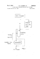
- FIG. 1 is a flow chart illustrative of typical aqueous waste treatment processes employing an oxidation ditch which may benefit from my invention
- FIG. 2 illustrates in plan view an oxidation ditch constructed in accordance with preferred embodiments of my invention
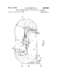
- FIG. 3 is a cross-sectional view of such a preferred ditch.
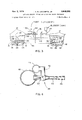
- FIG. 4 is a detailed view in section of an ejector assembly for use in my preferred oxidation ditch system.
- oxidation ditches Prior to my invention those skilled in this art believed that oxidation ditches required large rotating brushes to produce sufiicient liquid velocity to prevent the sludge from settling and to adequately mix the liquid and solids. In most cases this velocity consideration has been a limiting design factor and resulted in over-oxygen (more oxygen than necessary for treatment). While over-oxygenation is not harmful, it represents an unnecessary expenditure of horsepower and is, therefore, costly. It has been considered that other aeration devices such as ejectors, impellers, or the like would not be able economically to generate relatively high velocities and good mixing throughout the ditch. Contrary to these expectations, the ejector-oxidation ditch combination of my invention operates with sufiiciently high velocities for good mixing substantially throughout a properly designed ditch at lower horsepower inputs than are required for similar systems utilizing a rotating brush.
- raw efiiuent may be directed to the oxidation ditch. Alternatively it may undergo primary treatment in a settling tank or the like where heavier particulate matter is removed. From the oxidation ditch the treated liquid is usually sent to a separator where the sludge is eliminated. In some cases where the amount of sludge is small, a separator may not be required. The clarified liquid is released to a stream or other body of water, and the sludge is wasted or recycled in whole or in part to the oxidation ditch. Depending upon the type of waste being treated, the amount of sludge recycled may vary between 25% and 125% by volume of the incoming raw waste and, preferably, within the range of from 40% to 100%.
- the ditch defines a continuous, substantially closed course for liquid movement.
- the top 12 of the ditch is preferably well above the ditch bottom 14 and accommodates a liquid depth of up to feet or more.
- the sides 16 preferably form a trapezoid in cross-section with bottom 14 for ease of construction.
- Ditch 10 may be unlined or lined with materials now used such as poured concrete, shortcrete, or elastomeric membranes.
- a preferred configuration for ditch 10 is illustrated in FIG. 2 as an oval or racetrack shaped channel having island 18.
- the liquid flow path is preferably around the channel and free from obstructions to flow other than are unavoidably presented by the equipment to be used.
- a relatively wide turning radius R of about 3 times the channel width W is preferred for improved flow.
- a reduced radius R which is not to scale is shown in FIG. 2.
- inlet 20 and outlet 22 The actual location of inlet 20 and outlet 22 is not critical and may be at one end as shown. From a contacting and reaction kinetics viewpoint, the introduction of infiuent (inlet 20) should be located just downstream from the zone of efiluent draw oif (outlet 22). This allows every fraction of waste a certain minimum contacting and mixing time prior to possible washout from the system and insures against short circuiting. In large ditches this minimum contacting time could be as great as one hour. Unlike conventional flow-through systems, however, influent is not continuously introduced into a given portion of liquid since the ditch contents are constantly moving past the influent zone providing dilution and resistance to shock loading. As illustrated the influent may flow tangentially over wier 24 and the effluent tangentially over wier 26 to minimize interruptions in the flow pattern.
- One or more ejectors 28 can be used depending upon the size of the ejector and quantity of water liquid to be treated. It is contemplated, however, that most systems will require a plurality of ejectors which are preferably combined to form one or more ejector banks 30. In the illustrated embodiment where two banks 30 are used having five ejectors 28 in each, the banks are preferably located at the beginning of each straight portion of the ditch for optimum hydraulic flow around the bends.
- Motor 32 coupled to pump 34 provides for circulation of the ditch contents 35 through the ejectors 28.
- Blower 36 can be used to supply air to the ejectors 28 which is released as bubbles for mixing with the ditch contents.
- ejectors 28 are submerged within the ditch contents 35 so long as they are sufficiently below the surface 38 of channel contents 35 to prevent rapid dissipation of the energy from the ejectors.
- the deeper the ejectors are placed the greater will be the bubble contact time and the efifective oxygenation.
- greater depths tend to increase the shear forces on the bubbles as they enter the ditch contents, further subdividing them and increasing the surface area for oxygenation. For these reasons it is preferred that ejectors 28 be placed at or near the bottom 1.4 of ditch 10.
- Ejector banks 30, may be supported within the ditch 10 by any suitable means such as attachment to sides 16. Piping from pump 34 and blower 36 is indicated generally as 38 and 40, respectively, and may be arranged in any convenient manner.
- the number of ejectors 28 in each bank 30 should be sufficient to impact the waste liquid substantially completely across the ditch 10 as the flows from the ejectors expand and overlap a short distance downstream from ejector bank 30. All the ejectors in each bank are preferably directed along lines parallel to the desired direction of flow and spaced at equidistant locations across ditch 10. In this manner the ejectors preferably provide the sole motivating force to mix and move the ditch contents 35 about its circuitous path.
- FIG. 4 illustrates one embodiment of an ejector system.
- a channel 42 of the ejector 28 is in communication with header conduit 44 and receives therefrom a flow of air, oxygen, or the like at a relatively high velocity generated by blower 36 through piping 40 (FIGS. 2 and 3).
- Liquid is directed from the ditch itself via intakes 45 located within contents 35 and piping 46 through pump 34 and piping 38 to liquid header conduit 48.
- Header 48 feeds the liquid to each eductor 28 through its constriction 50 to mix with incoming gas at chamber 52. The velocity of the air-liquid mixture then is increased by travel through constriction 54 from which it is ejected through nozzle 56 into the ditch 10.
- the liquid passing at high velocity transversely of channel 42 creates a vacuum condition which aids air movement into the flowing liquid providing for a jet of air and liquid from the nozzle 56.
- the nozzle diameter increases slightly towards the outlet to accommodate the volume of the combined air and liquid streams while still maintaining high velocity.
- the high velocity air-liquid mixture jet impacts the liquid mass in the ditch urging it into motion.
- the combined action of the ejectors creates circuitous movement around the ditch as well as contacting the air with the liquid and occasioning good mixing action.
- Ejectors which I have found to be adapted for use in my system include Model 67 JA manufactured by Penberthy Division of Houdaille Industries, Inc. Others are made by Schute and Koerting Co.
- the oxidation ditch carries out both physical and biochemical processes.
- a minor portion of the organic matter present undergoes direct chemical oxidation while the rest is stabilized by the biochemical activities of the microorganism.
- the microorganisms feed on the organic matter and form biologically degradable and nondegradable products. These products combine with the microorganisms to form a floc that can be settled out in subsequent treatment as earlier described.
- the efliciency of the system is dependent upon good flocculation which relates to a high level of microorganism activity.
- EXAMPLE I This example demonstrates the reduced horsepower requirements resulting from the use of my invention when compared with a rotor brush as the commonly used means for aerating and moving waste-containing liquids in an oxidation ditch.
- the ditch utilized for this example was a test facility which, of necessity, compromised optimum flow design for flexibility. It comprised a channel 15 feet wide and 11 feet deep having vertical sides and generally of the shape illustrated in FIG. 1.
- the straight sections were 76 feet long, and a 7 foot wide, rotating brush with a 10 hp. motor was installed in a constriction at the midpoint of one of the straight sections. Because the bends were relatively sharp, turning guides were used to reduce the effect of the change in direction on the flow pattern.
- the ditch capacity was 225,000 gallons. For the purposes of this example the ditch was filled with water.
- Air and water pressures along conduits to and from the ejectors, pump, and blower were monitored. Air flow was measured with a rotameter, water flow with a magnetic flowmeter.
- the ejectors weer suspended from a float which was constructed of wood and empty drum and maintained in position by guywires equipped with Dilan strain gauges to measure the thrust generated by the jets. There were 10 Penberthy 67 JA ejectors mounted on air and water headers.
- a Gould centrifugal pump with a 7.5 hp. motor provided water to the ejectors while a Roots-Connorsville positive displacement blower provided air.
- the water flow and pressure were controlled by a DeZurik concentric V- port valve, and a bypass with valving controlled air flow pressure.
- Horsepower determinations for the rotating brush were based on ammeterreadings and previous data as well as the manufacturers information. Ejector horsepower determinations were based on theoretical calculations from air and Water flows and pressure differentials.
- the net air horsepower was calculated using the adiabatic work expression for a compressible gas. Since the work performed on the gas is equal to the product of the head and the weight of the gas handled, the adiabatic horsepower is where,
- the standard oxygen transfer rate was determined in the following manner,
- K the reaeration constant determined from the slope of a plot of dissolved oxygen deficit vs. time elapsed and corrected to 20 C.
- Velocity measurements were taken with either a Gurley No. 622' velocity current meter or a Marine Advisors Model B-la Savonius current speed sensor with a Model 56b current meter detector and a Model 5-14a current direction detector. Measurements were made at locations throughout the channel length, width and depth. Mean ditch velocity was calculated by averaging the values for each run.
- the ejectors were submerged at a depth of about '9 feet and canted at a slight downward angle of about 7.
- the following table summarizes the results of tests conducted during four such runs.
- velocities in the range of from flow path through which the confined liquid is moved about 0.3 f.p.s. to about 1.0 fps. are satisfactory dependand providing for a liquid depth of at least about 10 ing upon the solids size and density. feet,
- EXAMPLE II In this example an oxidation ditch was formed by a chest 48 feet long and 13 feet deep having two channels 6'7 wide separated by a midfeather. The walls were vertical and tile lined.
- Preliminary treatment of the incoming waste was accomplished by straining on a 3' by 3 horizontal screen of A-inch mesh. From the screen the stream flowed to the suction of the pump supplying one of the manifolds while the other manifold was supplied with mixed liquor from a separate pump. Air was supplied through a rotometer to one or both manifolds as desired. A sludge-blanket clarifier was used for final suspended solids removal.
- Table III lists operating data while Table IV summarizes the results obtained under conditions of about 30 hours retention time.
- ejectors for aerating the waste liquid in the ditch to reduce the BOD. thereof and for simultaneously moving the waste liquid through the flow path, the ejectors being constructed and arranged so that they are solely capable of circulating the waste liquid throughout the ditch at a velocity of at least 0.3 foot per second to maintain the settleable solids in suspension,
- said ejectors each comprising a housing having a waste liquid inlet for receiving a stream of pressurized waste liquid, a high velocity waste liquid nozzle in communication with said waste liquid inlet, an air inlet for receiving air, a mixing chamber in communication with said Waste liquid nozzle and said air inlet and a discharge outlet for discharging a high velocity waste liquid-air jet,
- said ejectors being arranged to discharge the waste liquid-air jets at least about 9 feet below the surface of the Waste liquid in the o idation ditch and in the direction of movement thereof,
- a method of treating waste liquid, which contains settleable solids and B.0.D., to reduce the B.O.D. while maintaining the settleable solids in suspension comprising 5 the steps of,
- an oxidation ditch defining a continuous, substantially closed flow path through which the confined liquid can be circulated, the ditch providing for a liquid depth of at least about feet
- the ejectors being constructed and arranged so that they are solely capable of circulating the waste liquid throughout in the ditch at a velocity of at least 0.3 foot per second.
Landscapes
- Chemical & Material Sciences (AREA)
- Life Sciences & Earth Sciences (AREA)
- Chemical Kinetics & Catalysis (AREA)
- Biodiversity & Conservation Biology (AREA)
- Microbiology (AREA)
- Hydrology & Water Resources (AREA)
- Engineering & Computer Science (AREA)
- Environmental & Geological Engineering (AREA)
- Water Supply & Treatment (AREA)
- Organic Chemistry (AREA)
- Treatment Of Water By Oxidation Or Reduction (AREA)
Abstract
1. A SYSTEM FOR TREATING WASTE LIQUID CONTAINING SETTLEABLE SOLIDS AND B.O.D. COMPRISING, AN OXIDATION DITCH FOR CONFINING AND RETAINING THE WASTE LIQUID AND DEFINING A CONTINUOUS, SUBSTANTIALLY CLOSED FLOW PATH THROUGH WHICH THE CONFINED LIQUID IS MOVED AND PROVIDING FOR A LIQUID DEPTH OF AT LEAST ABOUT 10 FEET, A PLURALITY OF EJECTORS FOR AERATING THE WASTE LIQUID IN THE DITCH TO REDUCE THE B.O.D THEREOF AND FOR SIMULTANEOUSLY MOVING THE WASTE LIQUID THROUGH THE FLOW PATH, THE EJECTORS BEING CONSTRUCTED AND ARRANGED SO THAT THEY ARE SOLELY CAPABLE OF CIRCULATING THE WASTE LIQUID THROUGHOUT THE DITCH AT A VELOCITY OF AT LEAST 0.3 FOOT PER SECOND TO MAINTAIN THE SETTLEABLE SOLIDS IN SUSPENSION, SAID EJECTORS EACH COMPRISING A HOUSING HAVING A WASTE LIQUID INLET FOR RECEIVING A STREAM OF PRESSURIZED WASTE LIQUID, A HIGH VELOCITY WASTE LIQUID NOZZLE IN COMMUNICATION WITH SAID WASTE LIQUID INLET, AN AIR INLET FOR RECEIVING AIR, A MIXING CHAMBER IN COMMUNICATION WITH SAID WASTE LIQUID NOZZLE AND SAID AIR INLET AND A DISCHARGE OUTLET FOR DISCHARGING A HIGH VELOCITY WASTE LIQUID-AIR JET, SAID EJECTORS BEING ARRANGED TO DISCHARGE THE WASTE LIQUID-JETS AT LEAST ABOUT 9 FEET BELOW THE SURFACE OF THE WASTE LIQUID IN THE OXIDATION DITCH AND IN THE DIRECTION OF MOVEMENT THEREOF.
D R A W I N G
D R A W I N G
Description
1974 I A. R. LECOMPTE, JR I 3,345.292
EJECTOR AERATED OXIDATION DITCH FOR WASTE TREATMENT Original Filed Anril 50, 1971 3 Sheets-Sheet 1.
RAW EFFLUENT V PRIMARY SETTLING TANK OXIDATION SLUDGE: D'TCH TOI RECYCLE:
l l v I l SLUDGE To SEPARATOR WASTE I TO STREAM NOV. 1974 AQR. LECOMPTE, JR 3,345,292
EJECTOR AERATED OXIDATION DITCH FOR WASTE TREATME NT Original Filed Avril 30, 1971 3 Sheets-Sheet 2 FIG. 2
Nov. 5, 1974 3,845,292
EJECTOR AERATED OXIDATION DI'I'CH FOR \us'rz: TREATMENT f A. R. LECOMPTE, JR
5 Sheets-Sheet 3 Original Filed Anril 30, 1971 PUMP (EFFLUENT) /BLOWER' (AIR) FIG. 3
FIG. 4
United States Patent 3,846,292 EJECTOR AERATED OXIDATION DITCH FOR WASTE TREATMENT Archie R. Lecompte, Jr., Neenah, Wis., assignor to Kimberly-Clark Corporation, Neenah, Wis.
Continuation of application Ser. No. 138,906, Apr. 30,
1971, which is a continuation-impart of application Ser. No. 75,620, Sept. 25, 1970, both now abandoned.
This application Oct. 5, 1973, Ser. No. 403,904
Int. Cl. C02c 1/06 U.S. Cl. 210-14 5 Claims ABSTRACT OF THE DISCLOSURE Oxidation ditch system for the removal of B.O.D. and suspended solids from aqueous waste by using ejectors to aerate the liquid and also as the sole propelling force to move the liquid around a closed-loop circuit. Advantages include reduced horsepower requirements and the use of deeper, high-volume ditches without reduction in aeration effectiveness.
This application is a continuation-in-part of my copending application S.N. 75,620 filed September 25, 1970.
This is a continuation of application Ser. No. 138,906, filed Apr. 30, 1971, now abandoned, which is a continuation-in-part of application Ser. No. 75,620 filed Sept. 25, 1970, now abandoned.
DESCRIPTION OF THE INVENTION The related problems of waste water treatment and effective water quality control are of increasing criticality to municipalities and industry as Well as the public in general. As the population expands, the need for manufactured products grows correspondingly which inherently results in the production of greater amounts of waste materials for treatment or disposal. Much of this waste has historically been directed to lakes and streams, but it is now recognized that improved equipment and methods for treating the waste must be developed to protect our water courses.
Broadly, systems for the treatment of aqueous wastes may be classified as either anaerobic or aerobic. Anaerobic processes involve the utilization of oxygen in its combined form. They typically require a long residence time and are accompanied by stagnant conditions and the generation of malodorous gases. Aerobic processes, in contrast, are characterized by oxygenation to promote the growth of microorganisms which feed on the particulate waste and break it down into harmless components, and the resulting biomass usually accumulates to form a sludge. My invention relates to aerobic systems for the treatment of aqueous waste.
Within the broad definition of aerobic processes set forth above there have been devised a number of treatment systems. Examples are aerated lagoons and activated sludge installations. All include, as a minimum, an inlet for the aqueous waste, a basin of sufiicient volume to provide a desired retention time, an outlet for the treated liquid, and some provision for maintaining the level of dissolved oxygen high enough to support microorganism growth and thereby prevent stagnant, anaerobic conditions from developing. Where the waste material is deficient in essential nutrients such as nitrogen or phosphorous, for example, they may be added to sustain the microorganisms.
Some oxygen may be supplied by simple exposure to the atmosphere. For example, Where the dissolved oxygen is depleted by the microorganisms, an oxygen deficit results between the concentration of oxygen in the water and that which the water can accommodate in equilibrium with the partial pressure of oxygen in the atmosphere. As long as this deficiency exists, oxygen will continue to diffuse into the water. For this arrangement to operate aerobically, however, large, shallow basins are necessary to provide suflicient surface exposure and retention time. In many cases the time and/or land area available is insufficient and additional sources of oxygen must be used.
An aerated lagoon is a similar arrangement where aeration devices are added to increase the transfer of oxygen into the aqueous waste. The resultant sludge either overflows to the receiving water body with the water or settles to the bottom and is removed from time to time. This requirement for sludge removal is a disadvantage since it can result in costly downtime.
Activated sludge installations also include the general components of inlet, basin, outlet, and aeration device. However, they provide in addition some system for keeping the aqueous waste in motion and substantially preventing the sludge from settling out. A separator device such as a clarifier is usually employed outside of the basin to divide the sludge from the treated liquid. The sludge, which contains biomass (i.e. microorganisms), is commonly returned in whole or in part to the basin to help treat fresh incoming waste. As a result, activated sludge installations contain greater amounts of active microorganisms and can operate at reduced retention times.
An oxidation ditch is a type of activated sludge installation wherein the basin forms a continuous, substantially closed course for liquid movement. A rotating brush positioned across the direction of liquid flow and partially submerged has commonly been used both for oxygenation and to move the liquid around the course. The quantity of waste liquid which can be treated for a given area has been limited by the depth of these ditches, commonly about 45 feet. Greater depths are generally uneconomical due to the horsepower required for a brush large enough to move the liquid. In addition brushes of greater diameter would be required to effectively treat waste material at the bottom of the ditch. Since the brush operates by rotating and causing a spray and turbulence, it is limited to a location at or near the liquid surface and limits the depth of the liquid which may be treated. For these reasons the oxidation ditch system of aqueous waste treatment has heretofore been principally restricted to low volume facilities.
It is a primary object of my invention to provide an improved oxidation ditch capable of relatively high volume treatment.
:More particularly it is an object of my invention to provide such an improved oxidation ditch that operates With reduced power requirements and increased oxygenation efilciency when compared with known oxidation ditch aeration installations.
Other objects of my invention include the substantial reduction in problems such as icing in cold weather, fogging, and foaming which have resulted from the use of conventional oxidation ditch systems.
Still other objects and advantages of my invention will become apparent upon reference to the detailed description and to the drawings, in which,
FIG. 1 is a flow chart illustrative of typical aqueous waste treatment processes employing an oxidation ditch which may benefit from my invention;
FIG. 2 illustrates in plan view an oxidation ditch constructed in accordance with preferred embodiments of my invention;
FIG. 3 is a cross-sectional view of such a preferred ditch; and
FIG. 4 is a detailed view in section of an ejector assembly for use in my preferred oxidation ditch system.
The use of an oxidation ditch in the form of a shallow,
' continuous circuit for the treatment of aqueous waste is old. The use of ejectors in activated sludge systems and the like for supplying oxygen to aqueous waste is also old. However, I believe that my improved combination of a relatively deep oxidation ditch with ejectors as the sole means for aeration and movement of the liquid is novel and produces beneficial and unexpected results.
Prior to my invention those skilled in this art believed that oxidation ditches required large rotating brushes to produce sufiicient liquid velocity to prevent the sludge from settling and to adequately mix the liquid and solids. In most cases this velocity consideration has been a limiting design factor and resulted in over-oxygen (more oxygen than necessary for treatment). While over-oxygenation is not harmful, it represents an unnecessary expenditure of horsepower and is, therefore, costly. It has been considered that other aeration devices such as ejectors, impellers, or the like would not be able economically to generate relatively high velocities and good mixing throughout the ditch. Contrary to these expectations, the ejector-oxidation ditch combination of my invention operates with sufiiciently high velocities for good mixing substantially throughout a properly designed ditch at lower horsepower inputs than are required for similar systems utilizing a rotating brush.
Turning now to the drawings, the generalized flow chart of FIG. 1 shows that raw efiiuent may be directed to the oxidation ditch. Alternatively it may undergo primary treatment in a settling tank or the like where heavier particulate matter is removed. From the oxidation ditch the treated liquid is usually sent to a separator where the sludge is eliminated. In some cases where the amount of sludge is small, a separator may not be required. The clarified liquid is released to a stream or other body of water, and the sludge is wasted or recycled in whole or in part to the oxidation ditch. Depending upon the type of waste being treated, the amount of sludge recycled may vary between 25% and 125% by volume of the incoming raw waste and, preferably, within the range of from 40% to 100%.
Referring now to FIGS. 2 and 3, the operation of the oxidation ditch will be described in greater detail. The ditch defines a continuous, substantially closed course for liquid movement. The top 12 of the ditch is preferably well above the ditch bottom 14 and accommodates a liquid depth of up to feet or more. The sides 16 preferably form a trapezoid in cross-section with bottom 14 for ease of construction. Ditch 10 may be unlined or lined with materials now used such as poured concrete, shortcrete, or elastomeric membranes.
A preferred configuration for ditch 10 is illustrated in FIG. 2 as an oval or racetrack shaped channel having island 18. The liquid flow path is preferably around the channel and free from obstructions to flow other than are unavoidably presented by the equipment to be used. A relatively wide turning radius R of about 3 times the channel width W is preferred for improved flow. For purposes of illustration a reduced radius R which is not to scale is shown in FIG. 2.
The actual location of inlet 20 and outlet 22 is not critical and may be at one end as shown. From a contacting and reaction kinetics viewpoint, the introduction of infiuent (inlet 20) should be located just downstream from the zone of efiluent draw oif (outlet 22). This allows every fraction of waste a certain minimum contacting and mixing time prior to possible washout from the system and insures against short circuiting. In large ditches this minimum contacting time could be as great as one hour. Unlike conventional flow-through systems, however, influent is not continuously introduced into a given portion of liquid since the ditch contents are constantly moving past the influent zone providing dilution and resistance to shock loading. As illustrated the influent may flow tangentially over wier 24 and the effluent tangentially over wier 26 to minimize interruptions in the flow pattern.
One or more ejectors 28 can be used depending upon the size of the ejector and quantity of water liquid to be treated. It is contemplated, however, that most systems will require a plurality of ejectors which are preferably combined to form one or more ejector banks 30. In the illustrated embodiment where two banks 30 are used having five ejectors 28 in each, the banks are preferably located at the beginning of each straight portion of the ditch for optimum hydraulic flow around the bends. Motor 32 coupled to pump 34 provides for circulation of the ditch contents 35 through the ejectors 28. Blower 36 can be used to supply air to the ejectors 28 which is released as bubbles for mixing with the ditch contents. While a single pump-blower set is illustrated, it will be understood that a pump and blower may be used for each ejector bank 30 if desired. Also, the location of the pump 34 and blower 36 is not critical although I believe that island 18 is a convenient, central location which can reduce the amount of piping used when a single set of pump and blower is to supply a plurality of ejector banks 30.
The particular depth at which ejectors 28 are submerged within the ditch contents 35 is not critical so long as they are sufficiently below the surface 38 of channel contents 35 to prevent rapid dissipation of the energy from the ejectors. In general, the deeper the ejectors are placed, the greater will be the bubble contact time and the efifective oxygenation. Also, greater depths tend to increase the shear forces on the bubbles as they enter the ditch contents, further subdividing them and increasing the surface area for oxygenation. For these reasons it is preferred that ejectors 28 be placed at or near the bottom 1.4 of ditch 10.
FIG. 4 illustrates one embodiment of an ejector system. A channel 42 of the ejector 28 is in communication with header conduit 44 and receives therefrom a flow of air, oxygen, or the like at a relatively high velocity generated by blower 36 through piping 40 (FIGS. 2 and 3). Liquid is directed from the ditch itself via intakes 45 located within contents 35 and piping 46 through pump 34 and piping 38 to liquid header conduit 48. Header 48, in turn, feeds the liquid to each eductor 28 through its constriction 50 to mix with incoming gas at chamber 52. The velocity of the air-liquid mixture then is increased by travel through constriction 54 from which it is ejected through nozzle 56 into the ditch 10. The liquid passing at high velocity transversely of channel 42 creates a vacuum condition which aids air movement into the flowing liquid providing for a jet of air and liquid from the nozzle 56. The nozzle diameter increases slightly towards the outlet to accommodate the volume of the combined air and liquid streams while still maintaining high velocity.
The high velocity air-liquid mixture jet impacts the liquid mass in the ditch urging it into motion. The combined action of the ejectors creates circuitous movement around the ditch as well as contacting the air with the liquid and occasioning good mixing action.
Ejectors which I have found to be adapted for use in my system include Model 67 JA manufactured by Penberthy Division of Houdaille Industries, Inc. Others are made by Schute and Koerting Co.
Reference may be had to US. application S.N. 75,619 filed Sept. 25, 1970, by Mikkel G. Mandt and assigned to the assignee of the present invention for a floating ejector arrangement that is particularly useful for my invention. In accordance with relevant aspects of that disclosure the pump and blower are attached to a float supporting submerged ejectors. Advantages include reduced piping and resultant head loss as well as increased flexibility since the unit may be moved to achieve desired results simply by shifting the float.
While it is not intended that my invention be limited to any particular theory, I believe that the oxidation ditch carries out both physical and biochemical processes. A minor portion of the organic matter present undergoes direct chemical oxidation while the rest is stabilized by the biochemical activities of the microorganism. The microorganisms feed on the organic matter and form biologically degradable and nondegradable products. These products combine with the microorganisms to form a floc that can be settled out in subsequent treatment as earlier described. The efliciency of the system is dependent upon good flocculation which relates to a high level of microorganism activity. An adequate supply of oxygen sustains the highly active microorganisms in the combination of my invention producing good flocculation with a clear efiluent from a final clarifier. B.O.D. removal of greater than 90% is obtainable as will be shown by the examples below.
EXAMPLE I This example demonstrates the reduced horsepower requirements resulting from the use of my invention when compared with a rotor brush as the commonly used means for aerating and moving waste-containing liquids in an oxidation ditch.
The ditch utilized for this example was a test facility which, of necessity, compromised optimum flow design for flexibility. It comprised a channel 15 feet wide and 11 feet deep having vertical sides and generally of the shape illustrated in FIG. 1. The straight sections were 76 feet long, and a 7 foot wide, rotating brush with a 10 hp. motor Was installed in a constriction at the midpoint of one of the straight sections. Because the bends were relatively sharp, turning guides were used to reduce the effect of the change in direction on the flow pattern. At a water depth of 10 feet the ditch capacity was 225,000 gallons. For the purposes of this example the ditch was filled with water.
Air and water pressures along conduits to and from the ejectors, pump, and blower were monitored. Air flow was measured with a rotameter, water flow with a magnetic flowmeter. The ejectors weer suspended from a float which was constructed of wood and empty drum and maintained in position by guywires equipped with Dilan strain gauges to measure the thrust generated by the jets. There were 10 Penberthy 67 JA ejectors mounted on air and water headers. A Gould centrifugal pump with a 7.5 hp. motor provided water to the ejectors while a Roots-Connorsville positive displacement blower provided air. The water flow and pressure were controlled by a DeZurik concentric V- port valve, and a bypass with valving controlled air flow pressure.
Horsepower determinations for the rotating brush were based on ammeterreadings and previous data as well as the manufacturers information. Ejector horsepower determinations were based on theoretical calculations from air and Water flows and pressure differentials.
The net air horsepower was calculated using the adiabatic work expression for a compressible gas. Since the work performed on the gas is equal to the product of the head and the weight of the gas handled, the adiabatic horsepower is where,
for air with k=1.395 and P =atmospheric,
Hp.=0.226 where Q is volume air rate Water horsepower was calculated from the expression,
piet+Qm 55 Where Ap =p =p =average jet manifold pressure minus hydrostatic head at ejector submergence in ft. of water Q =flow rate of water, lb./sec.
The standard oxygen transfer rate was determined in the following manner,
02 std Where K=the reaeration constant determined from the slope of a plot of dissolved oxygen deficit vs. time elapsed and corrected to 20 C.
D=dissolved oxygen deficit t=elapsed time (2o)) ata) 2 mass) The oxygenation capacity (OC) was then expressed in terms of the oxygen transfer divided by the sum of pump and blower horsepower. In the case of the rotating brush the no-load power consumption (rotor turning freely in air) was subtracted from the power consumption as measured by the recording Wattmeters and line ammeter readings.
Velocity measurements were taken with either a Gurley No. 622' velocity current meter or a Marine Advisors Model B-la Savonius current speed sensor with a Model 56b current meter detector and a Model 5-14a current direction detector. Measurements were made at locations throughout the channel length, width and depth. Mean ditch velocity was calculated by averaging the values for each run.
For this example, the ejectors were submerged at a depth of about '9 feet and canted at a slight downward angle of about 7. The following table summarizes the results of tests conducted during four such runs.
TABLE I 60 Run number A B C D Parameter Rotor Rotor Ejector Ejector Water depth (ft.) 10. 2 10. 5 10. 2 10. 3
Water differential pressure Ap,
p.51- 8. 3 7. 5 Air flow:
S e f m 77 155 P.s.i.g 3. 4 3. 9 Power input, hpJMG 13. 0 26. 1 12. 8 16. 9 Theoretical 0C, #Oz/hp.-hr 2. 48 3. 48 4. 97 5.77 0g lgased on manufacturer's Oa/shait hp.-hr 3. 16 4. 00 (Shaft input, hpJMG) (11. 6) (23. 7) Mean subsurface velocity, f.p.s 0. 28 0. 49 0. 42 0. 46 Approximate horizontal thrust (uncorrected) (lbs.) 78 83 Rotor submergence, in 3. 5 6.
This comparison demonstrates, I believe, that the use TABLE HI gf my invention resuts lI'l substalgitial lieitiefis indteBrms 3f Re'tention/fiow 298 hours/2&0 gpam Orsepower savmgs omparmg an t Mixed liquor suspended SOlldS-.. 4,479 mg./l. for example, theoretical oxygenation capac1t1es are shown Air rate 2L5 f which are about 200% and 165%, respectively, of thos 5 Dissolve; oxygen fl obtained with the rotating brush. When manufacturers Sludge volume index 142 m1. data are considered, the corresponding percentages are sludje Wasted 161 51bS /day about 140% and 133%, respectively. In terms of mean a velocity, my invention provides substantially higher results TABLE Iv when Runs A and C withnearly equal power inputs are Influent Eflillent Reduction mpar d and ly li h y l comparing R B Suspended solids 569 In /1-- 38.4 mg./l 93.3%. D where the rotor power input was about 155% that ap g-o p 206 -IL" 4. plied to the ejectors. Actual 0C values for other systems l u 'bid itzy mm, on such-as dilfuse and surface aerators generally range from about 1.0 to 2.5 lbs. 0 per horsepower hour. However 15 F th above it can be seen that my unique id other considerations such as maintaining solids in suspentio dit h ti arrangement provides very high B.O,D. sion may dictate use, of more power in these systems. In removal and good suspended solids removal. Thus, the contrast, my invention allows a greater degree of 56p advantages of oxidation ditch treatment are made availarate control of motive power through the pump and oxyable for locations of reduced area by means of deep gen transfer through the blower. channel aeration. Other advantages of my invention result A v i y Profile for a typical ejector run Where th from the fact that the moving parts are submerged. No power input was 15.3 Hp./mg., water depth was 10 feet, spray is produced which would be subject to icing in cold and ejectors were placed at a depth of 9 feet, appears as weather or fogging at other times. Also, the tendency to Table II. The mean velocity of this run was 0.4 f.p.s. Alfoam is reduced since the bubbles are released at a relathough the results demonstrate the ability of my system to tively deep location and move downstream to give a generate relatively high velocities throughout the chanlayered effect instead of piles of foam. I161 at ow hors pow r p I believe that improvements While the invention has been described with reference in design such as removing the rotor constriction and into specific embodiments, it is not to be restricted thereto. creasing the turning radius will result in even higher ve- In its broadest aspects, the invention may be variously emlocities. At equivalent power inputs, mean velocities of 0.5 bodied within the scope of the appended claims. to 0.6 fps. can be expected based on calculations for bet- I claim: ter designs. 1. A system for treating waste liquid containing settle- The preferred velocity is one that is great enough to able solids and B.O.D. comprising, maintain the solids in suspension and provide proper miX- an oxidation ditch for confining and retaining the Waste ing, but slow enough for the desired retention time for the liquid and defining a continuous, substantially closed ditch contents. Generally, velocities in the range of from flow path through which the confined liquid is moved about 0.3 f.p.s. to about 1.0 fps. are satisfactory dependand providing for a liquid depth of at least about 10 ing upon the solids size and density. feet,
TABLE II Outside turning Inside turning Outside edge guide Middle guide Inside edge Beginning of turn following ejectors..- 0. 6 0. 6 0. 6 0.3 0. 3 0. 4 End following ejectors 0.6 0.3 0.4 0.7 End of turn following ejectors 0.5 .6 .5 0.4 0.4 0.2 One-quarter point side opposite ejectors 0. 5 0.5 0. 5 o, 2 0 3 o 1 Three-quarter point-side opposite ejectors 0.4 0.5 0.5 Q2 (12 0,2 Beginning of turn approaching ejectors..- 0. 5 0. 5 0. 5 0, 1 o, 3 0,1 End approaching ejectors 5 5 6 0. 2 0.3 0. 4 End of turn approaching ejector 0.5 0.5 0.6 0.4 0.5 0.5 Following ejectors. 0- 6 4 3 0. 7 0.3 0. 8
EXAMPLE II In this example an oxidation ditch was formed by a chest 48 feet long and 13 feet deep having two channels 6'7 wide separated by a midfeather. The walls were vertical and tile lined.
- Two manifolds of three Penberthy Model 67 JA ejectors each were mounted on the bottom at the upstream end of the midfeather in each channel with the centerlines of the ejectors 12" off the door.
Preliminary treatment of the incoming waste was accomplished by straining on a 3' by 3 horizontal screen of A-inch mesh. From the screen the stream flowed to the suction of the pump supplying one of the manifolds while the other manifold was supplied with mixed liquor from a separate pump. Air was supplied through a rotometer to one or both manifolds as desired. A sludge-blanket clarifier was used for final suspended solids removal.
Table III lists operating data while Table IV summarizes the results obtained under conditions of about 30 hours retention time.
a plurality of ejectors for aerating the waste liquid in the ditch to reduce the BOD. thereof and for simultaneously moving the waste liquid through the flow path, the ejectors being constructed and arranged so that they are solely capable of circulating the waste liquid throughout the ditch at a velocity of at least 0.3 foot per second to maintain the settleable solids in suspension,
said ejectors each comprising a housing having a waste liquid inlet for receiving a stream of pressurized waste liquid, a high velocity waste liquid nozzle in communication with said waste liquid inlet, an air inlet for receiving air, a mixing chamber in communication with said Waste liquid nozzle and said air inlet and a discharge outlet for discharging a high velocity waste liquid-air jet,
said ejectors being arranged to discharge the waste liquid-air jets at least about 9 feet below the surface of the Waste liquid in the o idation ditch and in the direction of movement thereof,
9 2. The system of claim 1 wherein said ejectors are located near the bottom of said ditch.
3. A method of treating waste liquid, which contains settleable solids and B.0.D., to reduce the B.O.D. while maintaining the settleable solids in suspension comprising 5 the steps of,
confining and retaining the waste liquid to be treated in an oxidation ditch defining a continuous, substantially closed flow path through which the confined liquid can be circulated, the ditch providing for a liquid depth of at least about feet,
producing separate streams of pressurized waste liquid and of air,
combining said streams of liquid and air in a plurality of ejectors to produce a series of high velocity liquidair jets,
discharging said high velocity jets from said ejectors into the waste liquid in the ditch at a depth of at least about 9 feet below the surface thereof and in the direction of the waste liquid flow path to aerate the waste liquid in the ditch and to simultaneously circulate the waste liquid through said fiow path, the ejectors being constructed and arranged so that they are solely capable of circulating the waste liquid throughout in the ditch at a velocity of at least 0.3 foot per second.
4. The method as defined in claim 3 including the step of producing said streams of pressurized liquid by pump- 1 0 ing and circulating liquid from the ditch through a conduit and to said ejectors.
5. The method as defined in claim 3 including the step of pressurizing said streams of air before combining same with said streams of pressurized liquid in said ejectors.
References Cited UNITED STATES PATENTS 3,579,439 5/1971 Meiring et a1. 210--195 3,206,176 9/1965 Peterson 21014 2,606,150 -8/ 1952 Thorp 210-63 3,281,304 9/ 1966 Valdespino et a1 21014 3,397,789 8/1968 Valdespino 210195 3,505,212 4/ 1970 Huger 21014 3,336,016 8/1967 Schreiber 210220 3,510,110 5/1970 Klein 259-107 FOREIGN PATENTS 942,754 11/1963 Great Britain 261Dig.
vo-w UNITED STATES PATENT OFFICE a T CERTIFICATE OF CORRECTION Patent: No. 846,292 Dated November 5, 1974 Inventofls) Archie R. LeCompte, Jr. C
It is certified that error appears in the above-identified patent and that said Letters Patent are hereby corrected-as shown below:
. .1 Column 1, please delete lines 24 and 25. "This application is a continuation-in-part, of my copending application 'S.N. 75,620 filed September -25, 1970,." a
' sign to a minus Column 6, li-ne 2,2,changethe second equa Column 7, line 17, "dictate use". should read dictate the use l-=. Column 9, .claim 3, 'line 25, delete the word "in" Signedand sealed this 7th day of; January 1975.
(szAL) Attest:
. iMcCOY M, GIBSON JR. f v C. MARSHALL DANN Attest-ing'O-fficer e Commissioner-of Patents
Claims (1)
1. A SYSTEM FOR TREATING WASTE LIQUID CONTAINING SETTLEABLE SOLIDS AND B.O.D. COMPRISING, AN OXIDATION DITCH FOR CONFINING AND RETAINING THE WASTE LIQUID AND DEFINING A CONTINUOUS, SUBSTANTIALLY CLOSED FLOW PATH THROUGH WHICH THE CONFINED LIQUID IS MOVED AND PROVIDING FOR A LIQUID DEPTH OF AT LEAST ABOUT 10 FEET, A PLURALITY OF EJECTORS FOR AERATING THE WASTE LIQUID IN THE DITCH TO REDUCE THE B.O.D THEREOF AND FOR SIMULTANEOUSLY MOVING THE WASTE LIQUID THROUGH THE FLOW PATH, THE EJECTORS BEING CONSTRUCTED AND ARRANGED SO THAT THEY ARE SOLELY CAPABLE OF CIRCULATING THE WASTE LIQUID THROUGHOUT THE DITCH AT A VELOCITY OF AT LEAST 0.3 FOOT PER SECOND TO MAINTAIN THE SETTLEABLE SOLIDS IN SUSPENSION, SAID EJECTORS EACH COMPRISING A HOUSING HAVING A WASTE LIQUID INLET FOR RECEIVING A STREAM OF PRESSURIZED WASTE LIQUID, A HIGH VELOCITY WASTE LIQUID NOZZLE IN COMMUNICATION WITH SAID WASTE LIQUID INLET, AN AIR INLET FOR RECEIVING AIR, A MIXING CHAMBER IN COMMUNICATION WITH SAID WASTE LIQUID NOZZLE AND SAID AIR INLET AND A DISCHARGE OUTLET FOR DISCHARGING A HIGH VELOCITY WASTE LIQUID-AIR JET, SAID EJECTORS BEING ARRANGED TO DISCHARGE THE WASTE LIQUID-JETS AT LEAST ABOUT 9 FEET BELOW THE SURFACE OF THE WASTE LIQUID IN THE OXIDATION DITCH AND IN THE DIRECTION OF MOVEMENT THEREOF.
Priority Applications (1)
| Application Number | Priority Date | Filing Date | Title |
|---|---|---|---|
| US40390473 US3846292A (en) | 1971-04-30 | 1973-10-05 | Ejector aerated oxidation ditch for waste treatment |
Applications Claiming Priority (2)
| Application Number | Priority Date | Filing Date | Title |
|---|---|---|---|
| US13890671A | 1971-04-30 | 1971-04-30 | |
| US40390473 US3846292A (en) | 1971-04-30 | 1973-10-05 | Ejector aerated oxidation ditch for waste treatment |
Publications (1)
| Publication Number | Publication Date |
|---|---|
| US3846292A true US3846292A (en) | 1974-11-05 |
Family
ID=26836675
Family Applications (1)
| Application Number | Title | Priority Date | Filing Date |
|---|---|---|---|
| US40390473 Expired - Lifetime US3846292A (en) | 1971-04-30 | 1973-10-05 | Ejector aerated oxidation ditch for waste treatment |
Country Status (1)
| Country | Link |
|---|---|
| US (1) | US3846292A (en) |
Cited By (34)
| Publication number | Priority date | Publication date | Assignee | Title |
|---|---|---|---|---|
| US3990974A (en) * | 1975-08-06 | 1976-11-09 | Canton Textile Mills, Inc. | Waste treatment and solids separating system |
| US4009100A (en) * | 1974-01-30 | 1977-02-22 | Basf Aktiengesellschaft | Method of treating waste water with jet nozzles |
| US4082662A (en) * | 1973-02-05 | 1978-04-04 | Prince Jack E | Liquid waste treatment apparatus |
| WO1979000262A1 (en) * | 1977-11-04 | 1979-05-17 | J Reid | Flow control apparatus and process for an oxidation ditch |
| US4162971A (en) * | 1976-07-31 | 1979-07-31 | Bayer Aktiengesellschaft | Injectors with deflectors for their use in gassing liquids |
| US4189384A (en) * | 1974-04-26 | 1980-02-19 | Stamicarbon, B.V. | Gas treatment of liquid |
| US4199452A (en) * | 1977-10-03 | 1980-04-22 | Houdaille Industries, Inc. | Jet aeration channel system |
| US4231874A (en) * | 1976-12-14 | 1980-11-04 | Heiligtag Raymond W | Gyratory aerobic aeration treatment tank |
| US4323367A (en) * | 1980-06-23 | 1982-04-06 | Institute Of Gas Technology | Gas production by accelerated in situ bioleaching of landfills |
| US4396402A (en) * | 1980-06-23 | 1983-08-02 | Institute Of Gas Technology | Gas production by accelerated bioleaching of organic materials |
| US4436632A (en) | 1982-04-22 | 1984-03-13 | Beard Harold J | Clarifier skimmer |
| US4446018A (en) * | 1980-05-01 | 1984-05-01 | Armco Inc. | Waste treatment system having integral intrachannel clarifier |
| US4451373A (en) * | 1980-04-14 | 1984-05-29 | Water Pollution Control Corp. | Ring channel aeration apparatus and method |
| US4457844A (en) * | 1982-04-22 | 1984-07-03 | Beard Harold J | Continuous waste water clarification process |
| US4548712A (en) * | 1977-11-04 | 1985-10-22 | Reid John H | Conservation of momentum in a barrier oxidation ditch |
| US4643830A (en) * | 1977-11-04 | 1987-02-17 | Reid John H | Process for operating a total barrier oxidation ditch |
| US4645603A (en) * | 1977-11-09 | 1987-02-24 | Frankl Gerald P | Liquid aeration device and method |
| US4722785A (en) * | 1977-11-04 | 1988-02-02 | Reid John H | Partial or non-barriered oxidation ditch having momentum conservation and increased oxygen transfer efficiency |
| US4741870A (en) * | 1987-06-26 | 1988-05-03 | Aeromix Systems, Incorporated | Apparatus for treatment of liquids |
| US5041217A (en) * | 1977-11-04 | 1991-08-20 | Reid John H | Apparatus for maximizing biological use of entire volume of endless channel in an oxidation ditch |
| US5076929A (en) * | 1989-03-17 | 1991-12-31 | Leonhard Fuchs | Sewage lagoon system |
| US5078869A (en) * | 1989-03-20 | 1992-01-07 | Baker Hughes Incorporated | Clarifier cleaning apparatus |
| US5605417A (en) * | 1994-07-18 | 1997-02-25 | The Dragun Corporation | Method and apparatus for improving degradation of an unsecured landfill |
| US6090277A (en) * | 1996-06-26 | 2000-07-18 | Gb. Odobez S.R.L. | Reactor for the depuration of polluted waste waters |
| US6117324A (en) * | 1999-05-27 | 2000-09-12 | Clemson University | System and process for treating animal waste |
| US20030077770A1 (en) * | 2001-10-18 | 2003-04-24 | Clemson University | Process for ozonating and converting organic materials into useful products |
| US20030146140A1 (en) * | 1999-05-27 | 2003-08-07 | Clemson University | System and process for treating carbonaceous wastes |
| US20070163956A1 (en) * | 2005-12-23 | 2007-07-19 | Greene Annel K | System and process for reducing waste volume |
| US20080053898A1 (en) * | 2006-09-05 | 2008-03-06 | Aeration Industries International, Inc. | Wastewater treatment system |
| TWI472381B (en) * | 2011-05-02 | 2015-02-11 | Method for improving carbonation conversion of alkaline solid waste | |
| US9675942B1 (en) | 2013-10-15 | 2017-06-13 | Aeration Industries International, LLC. | Universal bridge and wall mounted aeration apparatus |
| AU2015282359B2 (en) * | 2014-12-24 | 2020-10-08 | Kliptank Limited | Aeration entrainment, fractionation and mixing system and a method of using same |
| US11406943B1 (en) | 2019-06-14 | 2022-08-09 | Aeration Industries International, Llc | Apparatus for treating fluids having improved aeration efficiency and dual function operation |
| US11596907B1 (en) | 2019-06-14 | 2023-03-07 | Aeration Industries International, Llc | Apparatus for treating fluids having improved aeration efficiency and operational durability |
-
1973
- 1973-10-05 US US40390473 patent/US3846292A/en not_active Expired - Lifetime
Cited By (49)
| Publication number | Priority date | Publication date | Assignee | Title |
|---|---|---|---|---|
| US4082662A (en) * | 1973-02-05 | 1978-04-04 | Prince Jack E | Liquid waste treatment apparatus |
| US4009100A (en) * | 1974-01-30 | 1977-02-22 | Basf Aktiengesellschaft | Method of treating waste water with jet nozzles |
| US4189384A (en) * | 1974-04-26 | 1980-02-19 | Stamicarbon, B.V. | Gas treatment of liquid |
| FR2333552A1 (en) * | 1975-08-06 | 1977-07-01 | Canton Textile Mills | LIQUID WASTE TREATMENT AND SOLID SEPARATION EQUIPMENT |
| US3990974A (en) * | 1975-08-06 | 1976-11-09 | Canton Textile Mills, Inc. | Waste treatment and solids separating system |
| US4162971A (en) * | 1976-07-31 | 1979-07-31 | Bayer Aktiengesellschaft | Injectors with deflectors for their use in gassing liquids |
| US4231874A (en) * | 1976-12-14 | 1980-11-04 | Heiligtag Raymond W | Gyratory aerobic aeration treatment tank |
| US4199452A (en) * | 1977-10-03 | 1980-04-22 | Houdaille Industries, Inc. | Jet aeration channel system |
| US4722785A (en) * | 1977-11-04 | 1988-02-02 | Reid John H | Partial or non-barriered oxidation ditch having momentum conservation and increased oxygen transfer efficiency |
| WO1979000262A1 (en) * | 1977-11-04 | 1979-05-17 | J Reid | Flow control apparatus and process for an oxidation ditch |
| US5041217A (en) * | 1977-11-04 | 1991-08-20 | Reid John H | Apparatus for maximizing biological use of entire volume of endless channel in an oxidation ditch |
| US4643830A (en) * | 1977-11-04 | 1987-02-17 | Reid John H | Process for operating a total barrier oxidation ditch |
| US4548712A (en) * | 1977-11-04 | 1985-10-22 | Reid John H | Conservation of momentum in a barrier oxidation ditch |
| US4645603A (en) * | 1977-11-09 | 1987-02-24 | Frankl Gerald P | Liquid aeration device and method |
| US4451373A (en) * | 1980-04-14 | 1984-05-29 | Water Pollution Control Corp. | Ring channel aeration apparatus and method |
| US4446018A (en) * | 1980-05-01 | 1984-05-01 | Armco Inc. | Waste treatment system having integral intrachannel clarifier |
| US4323367A (en) * | 1980-06-23 | 1982-04-06 | Institute Of Gas Technology | Gas production by accelerated in situ bioleaching of landfills |
| US4396402A (en) * | 1980-06-23 | 1983-08-02 | Institute Of Gas Technology | Gas production by accelerated bioleaching of organic materials |
| US4457844A (en) * | 1982-04-22 | 1984-07-03 | Beard Harold J | Continuous waste water clarification process |
| US4436632A (en) | 1982-04-22 | 1984-03-13 | Beard Harold J | Clarifier skimmer |
| US4741870A (en) * | 1987-06-26 | 1988-05-03 | Aeromix Systems, Incorporated | Apparatus for treatment of liquids |
| US5076929A (en) * | 1989-03-17 | 1991-12-31 | Leonhard Fuchs | Sewage lagoon system |
| US5078869A (en) * | 1989-03-20 | 1992-01-07 | Baker Hughes Incorporated | Clarifier cleaning apparatus |
| US5605417A (en) * | 1994-07-18 | 1997-02-25 | The Dragun Corporation | Method and apparatus for improving degradation of an unsecured landfill |
| US6090277A (en) * | 1996-06-26 | 2000-07-18 | Gb. Odobez S.R.L. | Reactor for the depuration of polluted waste waters |
| US6500333B1 (en) | 1999-05-27 | 2002-12-31 | Clemson University | System and process for treating waste water |
| US20030146140A1 (en) * | 1999-05-27 | 2003-08-07 | Clemson University | System and process for treating carbonaceous wastes |
| US6893565B2 (en) | 1999-05-27 | 2005-05-17 | Clemson University | System and process for treating carbonaceous wastes |
| US6117324A (en) * | 1999-05-27 | 2000-09-12 | Clemson University | System and process for treating animal waste |
| US7498163B2 (en) | 2001-10-18 | 2009-03-03 | Clemson University | Process for reducing solid waste volume and landfill mass |
| US20030077770A1 (en) * | 2001-10-18 | 2003-04-24 | Clemson University | Process for ozonating and converting organic materials into useful products |
| US6835560B2 (en) | 2001-10-18 | 2004-12-28 | Clemson University | Process for ozonating and converting organic materials into useful products |
| US20050141966A1 (en) * | 2001-10-18 | 2005-06-30 | Clemson University | Process for reducing sold waste volume and landfill mass |
| US7651615B2 (en) | 2005-12-23 | 2010-01-26 | Clemson University Research Foundation | Process for reducing waste volume |
| US20070163956A1 (en) * | 2005-12-23 | 2007-07-19 | Greene Annel K | System and process for reducing waste volume |
| US7892433B2 (en) | 2006-09-05 | 2011-02-22 | Aeration Industries International, Inc. | Wastewater treatment system |
| US8110108B2 (en) | 2006-09-05 | 2012-02-07 | Aeration Industries International LLC | Wastewater treatment system |
| US20080053898A1 (en) * | 2006-09-05 | 2008-03-06 | Aeration Industries International, Inc. | Wastewater treatment system |
| US7678274B2 (en) * | 2006-09-05 | 2010-03-16 | Aeration Industries International, Inc. | Wastewater treatment system |
| US20100170846A1 (en) * | 2006-09-05 | 2010-07-08 | Aeration Industries International, Inc. | Wastewater treatment system |
| US7465394B2 (en) * | 2006-09-05 | 2008-12-16 | Aeration Industries International, Inc. | Wastewater treatment system |
| US20110108479A1 (en) * | 2006-09-05 | 2011-05-12 | Aeration Industries International, Inc. | Wastewater treatment system |
| US20090071899A1 (en) * | 2006-09-05 | 2009-03-19 | Aeration Industries International, Inc. | Wastewater treatment system |
| US8236174B2 (en) | 2006-09-05 | 2012-08-07 | Aeration Industries International LLC | Wastewater treatment system |
| TWI472381B (en) * | 2011-05-02 | 2015-02-11 | Method for improving carbonation conversion of alkaline solid waste | |
| US9675942B1 (en) | 2013-10-15 | 2017-06-13 | Aeration Industries International, LLC. | Universal bridge and wall mounted aeration apparatus |
| AU2015282359B2 (en) * | 2014-12-24 | 2020-10-08 | Kliptank Limited | Aeration entrainment, fractionation and mixing system and a method of using same |
| US11406943B1 (en) | 2019-06-14 | 2022-08-09 | Aeration Industries International, Llc | Apparatus for treating fluids having improved aeration efficiency and dual function operation |
| US11596907B1 (en) | 2019-06-14 | 2023-03-07 | Aeration Industries International, Llc | Apparatus for treating fluids having improved aeration efficiency and operational durability |
Similar Documents
| Publication | Publication Date | Title |
|---|---|---|
| US3846292A (en) | Ejector aerated oxidation ditch for waste treatment | |
| EP0933334B1 (en) | Treatment tank for AEROBICALLY TREATING WASTEWATER comprising carriers | |
| US6592762B2 (en) | Process for treating BOD-containing wastewater | |
| US4455232A (en) | Method and apparatus for induced-flow circulation and pressurized aeration in a barrier oxidation ditch | |
| US4009100A (en) | Method of treating waste water with jet nozzles | |
| US4199452A (en) | Jet aeration channel system | |
| US4443338A (en) | Conversion of plug flow and complete mix aeration basins to barrier oxidation ditches | |
| US3733263A (en) | Waste treatment system | |
| US4421648A (en) | Apparatus and a method for biological treatment of waste waters | |
| US4532038A (en) | Flow control apparatus for aerobic sewage treatment | |
| US3893924A (en) | Aerobic lagoon waste treatment system and method | |
| EP2188223B1 (en) | Method and apparatus for aeration | |
| CA2247409C (en) | Treatment of waste liquor in a vertical shaft bioreactor | |
| US4394268A (en) | Conversion of plug flow and complete mix aeration basins to barrier oxidation ditches | |
| US4290884A (en) | Nitrification-denitrification system | |
| US3589997A (en) | Method for purifying waste water | |
| US3620512A (en) | Aerating apparatus | |
| US3788477A (en) | Treatment apparatus | |
| US3675779A (en) | Apparatus used in purifying waste water | |
| US4282102A (en) | Activated sludge wastewater treatment having suspended inert media for biota growth | |
| JPH0131438B2 (en) | ||
| US3207313A (en) | Apparatus for aeration of waste products | |
| US4353800A (en) | Method and an apparatus for biological treatment of waste waters | |
| US4202762A (en) | Process and device for the aeration of waste water | |
| US3236767A (en) | Waste treatment process |