US3843877A - Air data computer including dc to synchro signal converter - Google Patents
Air data computer including dc to synchro signal converter Download PDFInfo
- Publication number
- US3843877A US3843877A US00330164A US33016473A US3843877A US 3843877 A US3843877 A US 3843877A US 00330164 A US00330164 A US 00330164A US 33016473 A US33016473 A US 33016473A US 3843877 A US3843877 A US 3843877A
- Authority
- US
- United States
- Prior art keywords
- signal
- oscillator
- sine
- cosine
- signals
- Prior art date
- Legal status (The legal status is an assumption and is not a legal conclusion. Google has not performed a legal analysis and makes no representation as to the accuracy of the status listed.)
- Expired - Lifetime
Links
Images


Classifications
-
- G—PHYSICS
- G06—COMPUTING; CALCULATING OR COUNTING
- G06G—ANALOGUE COMPUTERS
- G06G7/00—Devices in which the computing operation is performed by varying electric or magnetic quantities
- G06G7/12—Arrangements for performing computing operations, e.g. operational amplifiers
- G06G7/22—Arrangements for performing computing operations, e.g. operational amplifiers for evaluating trigonometric functions; for conversion of co-ordinates; for computations involving vector quantities
Definitions
- a reference dc. voltage is converted to a time period ratio by utilizing an oscillator to generate a reference a.c. time base and a counter and integrator means for determining the time period ratioed with the reference time base.
- This time period ratio is used to sample the oscillator to obtain signals proportional to the sine and cosine values of the ac. time base which may then be converted to conventional resolver or threewire synchro signal altitude data.
- a second oscillator, controlled by the counter means and having a frequency which bears a predetermined ratio to the timing oscillator may also be sampled by the time period ratio and the sine and cosine values thereof converted to conventional resolver format or three-wire synchro signal format bearing said ratio to the first synchro signal output. Fine and coarse synchro signal altitude data is thus obtained.
- counter means synchronized to the reference oscillator and the first mentioned counter is employed to provide digital data proportional to the variable d.c. altitude signal for conversion to altitude reporting signal format.
- the present invention relates generally to direct current-to-synchro or resolver signal conversion arrangements and more specifically to such an arrangement for use in air data computers for aircraft for converting a dc. signal proportional to altitude to fine and coarse synchro signal format. Further means are provided for converting said d.c. altitude signal to digital format for use in generating a specially coded signal for altitude reporting purposes.
- One of the primary outputs of an air data computer system for aircraft is a measure of the aircrafts altitude since it is a primary navigation flight control term.
- the systems utilizing the altitude data require that it be in three-wire synchro signal format or four-wire synchro resolver format.
- federal air traffic control regulations require commercial carriers to be equipped with apparatus whereby when interrogated by ATC, a signal proportional to the aircrafts altitude be automatically transmitted to the ATC and displayed adjacent the ATCs blip" display of the interrogated aircraft. This is referred to as altitude reporting.
- the altitude signal must also be converted into digitally coded format, i.e., the International (ICAO) Altitude Reporting Code which is the Moa Gilam code. This code is disclosed in a publication entitled Mark 2 Subsonic Air Data System issued Feb. 15, 1968, page 55, published by ARINC, Annapolis, Maryland.
- the vibrating diphragm pressure sensor provides an output frequency which varies in accordance with altitude, the pressure/frequency relation being inherently but predeterminedly non-linear, as shown in the above-referenced Frische patent.
- This frequency signal is converted to a corresponding d.c. signal and linearized with altitude by means of a feedback circuit including a function generator having the said predetermined function characteristic.
- the magnitude of the dc. signal proportional to instantaneous altitude is ratioed with a reference d.c. signal whose magnitude is proportional to full scale altitude, i.e., maximum indicated altitude, and converted to a corresponding time period ratio using a dual slope integrator controlled by a time reference.
- the basic timing reference for the system comprises a sine/cosine oscillator of a predetermined convenient frequency, the sine wave output being used as the timing reference.
- This oscillator also provides the fine" synchro data as will be described below.
- Precise timing is achieved by converting the sine wave to an alternating square wave of like period.
- This reference square wave is applied to a counter which in turn controls switches which supply the variable d.c. signal to the dual slope integrator (which is controlled so as always to start from zero) for a fixed number of periods followed by the reference d.c. signal, in the opposite sense, for a like (or substantially like) number of periods. Since the integration rate of the integrator is constant, the magnitude of its output will vary as a function of the value of the variable do.
- the instant that the output of the integrator returns to zero will determine the exact time ratio between the variable do. and the fixed d.c.
- the instant the integrator output returns to zero will represent the instantaneous altitude and may be used to sample the oscillator sine wave and cosine wave to thereby provide d.c. signals proportional respectively to the fine sine and cosine values of the variable d.c. or altitude signals.
- the coarse" value of the variable d.c. or altitude signal is provided by a second sine/cosine oscillator having a frequency corresponding to the conventional 1/27 ratio commonly used in fine/coarse synchro systems.
- This coarse sine/cosine oscillator is controlled to start at a precise time by means of a zero crossing sample pulse provided by the counter responsive to the sine component of the fine oscillator.
- the coarse sine/cosine oscillator is set to an initial condition where sine l and cosine 0. At a predetermined number of counts thereafter the coarse oscillator is started.
- the coarse oscillator would be started at a point such that the positive going sine wave would cross zero precisely at the start of the second count (dual slope integrator switched to receive the reference d.c. signal). However, since negative altitudes must be accommodated, the coarse oscillator is started at a point such that the coarse sine wave crosses zero (corresponding to zero altitude) at a point slightly after the start of the second count. As with the fine oscillator, the sample pulse output of the dual slope integrator is also used to sample the coarse oscillator output to thereby provide d.c. signals proportional to the coarse sine and cosine values respectively of the variable d.c. or altitude signal.
- Each of the fine sine/cosine and coarse sine/cosine d.c. signals are modulated at the desired synchro trans- 3 mission frequency, typically 400 Hz, and then applied directly to respective fine and coarse synchro resolvers or to Scott T transformers to provide resultant fine and coarse signals in three-wiresynchro signal format for transmission to utilization devices.
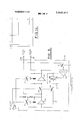
- FIGS. la, lb, and la constitute a schematic block diagram of the air data system of the present invention.
- FIGS. 2a and 2b. are a series of timing curves useful in disclosing the operation of the system.
- FIG. 3 is a schematic detail of a portion of the system of FIGS. 1a and lb.
- the source of pressure altitude data comprises a vibrating diaphragm pressure sensor 10, which may be of the type disclosed in the above-referenced Frische patent, the output 11 of which is an a.c.signal having a frequency as a function of sensed pressure.
- a calibration circuit 12 includes a temperature compensator 13, a frequency-tod.c. converter 14, a calibration network 15, and a summing amplifier 16.
- the thermal compensator may include a thermal sensor within the sensor 10 for compensating any effect due to changes in ambient temperature on the sensor.
- the frequency-to-d.c. converter 14 may be conventional but preferably is of the type disclosed in Applicants Assignees copending US. Pat.
- the basic timing reference for the system is a sine/cosine oscillator 20 tuned to a convenient frequency, depending upon'the desired resolution characteristic represented by the system cycle or refresh period. For example, in one application a frequency of about 330 Hz was found to be satisfactory.
- the sine wave output of oscillator 20 appears on lead 21 while the cosine wave output appears on lead 22.
- These signals are represented in curves (1) and (2) respectively of the timing diagrams of FIG. 2.
- the sine wave output has been chosen for convenience as the timing reference for the system although the cosine wave could similarly be used.
- the sine wave output of oscillator 20 is converted to a square wave by a conventional squaring amplifier or square wave generator 23.
- the output of generator 23 is illustrated by curve (3) of FIG. 2 and has a period l/f where f is the frequency of oscillator 20.
- variable d.c.-to-synchro signal converter of the present invention is based on the concept of converting the ratio of the variable d.c. signal and a reference d.c. signal to a time period ratio wherein the time period reference is the sine wave output of the oscillator 20.
- the variable dc. voltage proportional to instantaneous altitude is integrated over a period of time corresponding to a desired full scale reading of altitude, e.
- a reference dc voltage of opposite polarity from that of the variable dc. voltage but whose magnitude or amplitude also corresponds to said full scale reading is immediately integrated by the same integrator, the reference dc. voltage being applied to the integrator for a like period of time, i.e., corresponding to the same number of oscillator cycles. Since the slope of the integrator output in response to the variable d.c. signal varies with the magnitude thereof, i.e., actual altitude, over a period of time corresponding to full scale altitude and the slope of the integrator output in response to the reference d.c.
- the integrator output goes to zero represents the ratio of the magnitude of the variable dc. voltage or actual altitude to the reference dc. voltage or full scale altitude in'terms of the time period ratio of the number of oscillator cycles corresponding to actual altitude to the number of cycles corresponding to full scale altitude.
- the time period T is determined by a predetermined number, say 10, of sine wave cycles of the oscillator.
- Coarse altitude data may be obtained by means of a second sine/cosine oscillator having a frequency which is a predetermined fraction of the fine data frequency, typically one twenty-seventh thereof. If the coarse oscillator is controlled such that the positive going sine wave crosses zero at the instant the reference d.c. is applied to the integrator and sampled at the same instant T the instantaneous values of the coarse oscillator outputs are as follows,
- the timing of the coarse data is modified slightly. This modification is accomplished by adding a single cycle to the time period that the reference d.c. signal is applied to the integrator and controlling the start of the coarse oscillator such that its positive going sine wave crosses zero slightly after the application of the reference dc to the integrator. In one application of the present invention, such delay amounted to one quarter of a fine cycle which corresponded to 1,250 feet such that the coarse data started at 1,250 feet below sea level, sufficient to account for all areas of the earth at maximum atmospheric pressures.
- the coarse sampled data equations may be rewritten:
- FIGS. 1a and 1b A preferred embodiment of an implementation of the foregoing concept as applied to aircraft altimetry will now be described, reference again being made to FIGS. 1a and 1b.
- the principle element of the converter is a dual slope integrator 24 responsive to the output of a multiplexer 25 which is controlled by a counter 26 responsive in turn to the square wave produced by square wave generator 23 corresponding to the sine output of oscillator 20.
- Multiplexer 25 comprises a pair of switches 27 and 28 connected respectively to the variable dc. voltage proportional to instantaneous altitude on lead 17 and a reference dc. voltage produced by reference d.c. network 29, the magnitude of which corresponds to some maximum, a full scale altitude.
- switches '27 and 28 may be solid state devices such as for example conventional FET typ'e devices.
- Counter 26 is a count to 201 counter and is the system sequence timer and comprises a conventional binary counter adapted to count 21 periods of the square wave generator 23 output, which 21 counts constitute The output of integrator 30 will decrease at a slope dependent upon the magnitude of the variable d.c. signal (altitude signal 17 from sensor 10) and the integrator time constant whereby at the end of the 10th count, the magnitude of the integrator output will be proportional to the magnitude of the variable d.c. times the time period T divided by the integrator time constant.
- counter 26 switches switch 27 open and switch 28 closed and the switches remain in this condition for the next 11 counts of the counter or at least until the integrator output returns to zero.
- the output of integrator 30 is applied to a conventional zero crossing detector 31 so that when the integrator output reduces to zero, the detector supplies an output or sampling pulse.
- the sample pulse can be used to reset the integrator to zero via the reset circuit30' or alternatively, the sample pulse may be used to open switch 28 to assure the integrator will be zeroed for the start of the next cycle.
- the sampling pulse will occur at the time T which varies in accordance with the ratio of the magnitude of the variable do. and the reference d.c. voltages in terms of the number of oscillator cycles corresponding to time T and the number of cycles corresponding to the reference time base T (see curves (1) and (7) of FIG. 2).
- sample and hold circuits 32 and 33 responsive to the sine and cosine 0ut-' puts 21 and 22, respectively, of oscillator 20.
- the sample and hold circuits 32 and 33 are conventional and are adapted to supply a direct current output proportional to the value of the signal input at the instant the enabling pulse is applied. Therefore, at the instant T the sampling pulse is applied to the sample and hold circuits 32 and 33, the respective outputs 34 and 35 thereof are do voltages proportional respectively to the instantaneous sine and cosine values of pressure altitude.
- These signals are applied respectively to modulato'rs 36 and 37 where they are converted to corresponding modulated a.c. signals as will be described below.
- the sampling pulse may also be supplied to oscillator 20 to momentarily hold it at its then achieved sine-cosine values.
- the holding time need only be very short, e.g., microseconds and this momentary hold will not materially effect the system accuracy since any slight delay in the oscillator output will only delay the start of the next system cycle.
- count to twenty-one counter 26 is counts of the basic sine wave time reference provided by oscillator 20.
- counter 26 supplies binary count signals to control logic 38 which is designed to produce the curves (8), (9), (11) and (12) of FIG. 2 and their operation will now be described.
- the coarse synchro data was supplied by a second oscillator having a frequency which is a predetermined fraction of the fine data frequency of oscillator 20. Conventionally, this frequency is 1/27 of the fine data frequency.
- This source of coarse data frequency is coarse oscillator 40 which supplies coarse sine and cosine waves.
- the coarse oscillator is controlled by the counter 26.
- the positive going coarse sine wave be controlled so as to cross zero slightly after the start of the full scale fine sine wave to accommodate below sea level altitudes. This control is accomplished in two steps. First, the coarse oscillator is preconditioned at the start of each system cycle so that the sine value is 0 and the cosine value is 1. Furthermore, inasmuch as it is critical that the coarse oscillator 40 positive going sine wave crosses zero precisely at zero altitude, its frequency must be further controlled by the counter logic 38 through sine wave frequency control 41.
- the coarse oscillator 40 and its zero crossing control 4] are schematically illustrated in FIG. 3.
- the basic oscillator is conventional comprising a pair of series connected integrator amplifiers 45, 46 having a full loop feedback connection 47 to maintain the system in oscillation.
- This feedback connection 47 includes means for varying the oscillator frequency schematically illustrated as a variable gain amplifier 48.
- the sine wave output 49 is taken from the output of the first integrator while the cosine wave is taken from the output 50 of second integrator 46.
- the oscillator elements are selected so that its nominal frequency is in the neighborhood of one twenty-seventh the frequency of the fine oscillator 20 but which frequency can be varied slightly by means of frequency control 41 for purposes to be described below.
- the coarse oscillator 40 is preconditioned at the beginning of each system cycle by means of a condition gate illustrated by curve (8) of FIG. 2.
- This gate controls switches 51, 52 in each of the capacitive feedback loops of the integrators 45, 46, respectively, which switches are illustrated as mechanical switches but which in practice may be electronic FET type switches.
- Switch 51 shorts the integrator feedback capacitor 100 of integrator amplifier 45 and applies a predetermined fixed voltage to its input so that its output reprints a 1," corresponding to the peak amplitude of the oscillator while switch 52 shorts out the integrator feedback capacitor 101 of integrator 46 thereby causing its output amplitude to go to zero.
- This initial condition is maintained by means of the stop gate illustrated by curve (8a) of FIG.
- the coarse oscillator 40 must be precisely started so that the positive going sine output crosses zero at a point, relative to the start of the full scale sine wave from the fine oscillator 20, corresponding to zero altitude.
- the control logic 38 controlled by counter 26 is designed to turn off gate (8) and turn on gate (8a) precisely at a count of 3.5 cycles of sin (wt) (curve (1) of FIG. 2). Since in the specific embodiment illustrated, a full coarse oscillator cycleis not required and a quarter wave of the fine sine wave is difficult to pinpoint, some'means of assuring that positive going sine wave crosses zero at a point corresponding to zero altitude is required.
- the zero crossing gate is illustrated by curve (9) of FIG. 2.
- This gate is initiated by counter logic 38 precisely at the count of 10 and is terminated precisely one-half fine sine wave cycle later.
- switch 55 is closed and the coarse sine wave output from coarse oscillator 45 is applied to the integrator 56. If the coarse sine wave crosses zero precisely at the middle of the gate period equal positive and negative voltages will be applied to the integrator and its output will be zero. However, if the coarse sine wave does not cross zero at the middle of the gate the resultant integrator output will adjust thegain of feedback amplifier 48 to thereby adjust the frequency of the oscillator 40 in a direction to balance the integrator output. It will be understood'that this frequency adjustment may require a number of system cycles to accomplish the zero crossing adjustment.
- sampling gate output of crossover detector 31 is used to enable the same and clamp the then existing values of the coarse sine and cosine waves, whereby to provide on output leads 62 and 63 direct current voltages respectively proportional to the coarse sine and coarse cosine values of altitude. Also, as in the case of the fine data, these voltages are applied to modulators 64 and 65 to provide corresponding a.c. signals having magnitudes proportional respectively to the coarse sine and coarse cosine values of the variable d.c. input voltage and in the present embodiment, of aircraft altitude.
- the modulators 36 and 37 and 64 and 65 are all identical and therefore only modulator 36 need be de-' scribed.
- the dc. signal proportional to the sine of the variable d.c. input or altitude signal is applied to an integrator 66 through a summing junction 67.
- the integrator output is then applied to a modulator 68 excited with a reference alternating current supply (not shown) having a frequency corresponding to the frequency of the utilization system receiving the altitude signal, which frequency is typically 400 Hz in aircraft applications.
- the output of the modulator 68 is then suitably amplified in amplifier 69.
- a modulator feedback loop couples the output of the modulator 68 back to summing junction 67 through a demodulator 70. In operation, the input d.c.
- proportional to the sine of aircraft altitude sets the level of the output of integrator 66 to a corresponding value after which this signal is converted to a 400 Hz a.c. signal having an amplitude and phase proportional to the magnitude and sign of the input d.c.
- the modulator output is degeneratively fed back to the integrator 66 input to adjust its output signal level accordingly.
- the fine and coarse sine/cosine a.c. outputs of modulators 36, 37, 64 and 65, respectively, may be used directly in resolver format, i.e., as inputs 71, 72 to fine/- coarse resolvers forming part of the altitude utilization system or if desired or required may be converted to three-wire synchro format through two-wire to threewire circuitry 73, 74, such as Scott T transformers, as shown, or other equivalent solid state circuits.
- the pressure altitude signal is converted to a digital format for altitude reporting purposes.
- This digital format is that required by the ARINC standard for subsonic air data systems, known as ARINC Characteristic No. 565, in short, the abovementioned ICAO format.
- the altitude digitizer is shown in FIG. Id.
- the time base provided by the sine/cosine fine oscillator 20 starts and stops a high frequency oscillator or clock 75, the output of which is counted in counter 76 which is filled completely and checked for alignment with the fine oscillator sine output 20 during the initial operation of the dual slope integrator 24 by means of a synchronization technique to be described.
- the time base is then converted to altitude, by restarting the counter 76, with a least significant bit value of 100 feet.
- the Moa Gilam or ICAO decoder 77 converts the altitude count to ICAO code, the output of which is latched by latches 78 by the same sample pulse which enabled the coarse and fine sample and hold circuits 62, 63 and 32, 33 at actual altitude.
- the latched output of decoder 77 is supplied in IACO format to the aircraft transponder (not shown) which reports aircraft altitude to ATC.
- the counter clock or oscillator 75 must be preciselysynchronized with the fine sine/cosine oscillator 20. This is accomplished during the time the dual slope integrator 24 is integrating the do altitude signal from sensor 10, i.e., the first l cycles of the fine oscillator sine wave, by-the synchronizing circuitry generally indicated at 80 in FIG. 1d.
- the clock 75 is a voltage controlled oscillator having a nominal frequency proportional to the frequency of oscillator in one embodiment the oscillator 20 frequency was 330 Hz and the counter clock 75 frequency was nominally 33 KHz.
- the technique for precisely synchronizing these oscillators is similar to that for synchronizing the coarse oscillator 40 to the fine oscillator 20 in that synchronization may require several system refresh cycles.
- the clock oscillator 75 must be precisely synchronized with the completion of the tenth cycle of the fine altitude sine wave (1) which corresponds to the start of the altitude measure. Due to the rather large frequency ratio between these two oscillators, their synchronization is achieved by a fine/coarse technique to eliminate any possible ambiguity. Coarse synchronization is achieved as follows.
- the high frequency clock 75 is enabled, curve (11) of FIG. 2 with the start of the fine oscillator sine wave l) and the counter 76 begins to count the high frequency pulses.
- Binary coded decimal counter 81 counting from 50 to 499 fills and overflows into binary counter 82 which counts from 500 to 7,999.
- coarse sample gate having a width of about 25 microseconds shown magnified in curve (12) of FIG. 2, is generated in encoder control logic 84 which is responsive to oscillator and the fine sine wave (1) is sampled at this point of time.
- the fine sine wave from oscillator 20 is applied to a limiter and a squaring amplifier'86, the output of which is coupled with an integrating amplifier 87 through switch 88 controlled by the 5,000 ft coarse sample gate from encoder control logic 84.
- the latter switch is preferably an F ET type solid state switch although herein shown schematically.
- Limiter 85 serves to shape the square wave output of square wave amplifier 86 such that there is a dead zone of a predetermined width about the zero value of the sine wave as illustrated by the dotted curve of waveform (1) at cycle 1 of FIG. 2.
- the oscillators are coarse" synchronized and no signal is applied to integrator 87.
- the oscillators are not coarse synchronized, when the 5,000 ft gate closes switch 88, a portion of the square wave voltage will be applied to integrator 87, the magnitude and polarity of which will be dependent upon the time lead or lag between the occurrence of the gate and the fall or rise of the square wave.
- the resulting output of integrator 87 will therefore be supplied to voltage controlled oscillator or clock 75 and adjust its frequency and hence the time of occurrence of the coarse gate in a sense to bring the coarse gate within the limited square wave deadzone.
- Fine synchronization of the oscillators 20 and 75 is accomplished in a similar manner during the first 10 cycles of operation of dual slope integrator 24.
- Counter 76 continues to count the output pulses of the high frequency oscillator 75, binary counter 82 overflowing into binary counter 83 and at the count of 50 thousand, a 50K foot fine sample gate is generated in logic 84 which gate is used to sample the fine sine wave from oscillator 20.
- This fine sample gate is waveform (13) of FIG. 2.
- the fine sine wave is applied to squaring amplifier the output of which is applied to integrator 87 through fine sample switch 91 controlled by the fine sample 50K foot gate.
- the fine square wave is full width as illustrated by the dotted line curve in waveform (1) at cycle 10 in FIG. 2.
- the end of the 10th cycle of the fine sine wave corresponds to 50,000 feet, i.e., the sine wave crosses zero at a point correspondingto 50K feet.
- the fine gate will equally straddle the zero crossing of the fine sine wave and switch 91 will pass equal positive and negative portions of the'square wave from square wave amplifier 90 resulting in no net output from integrator 87.
- switch 91 will pass unbalanced portions of the square wave to integrator 87, the resultant output of which adjusts voltage controlled oscillator or clock 75 in a sense to move the 50K foot gate so as to equalize the portions of the square wave passed to integrator 87.
- this synchronization process may require a number of system refresh cycles to complete.
- control logic 38 supplies a short pulse of, say 200 microseconds, on lead 95 (curve not shown in FIG. 2)
- This reset output disables the fine sample gate, waveform (13) and the coarse sample gate, waveform (12) and thereby inhibits the operation of switches 88 and 91 so that no change in oscillator 75 frequency occurs during the actual altitude count.
- counter 26 supplies a pulse, curve (15) of FIG. 2, through control logic 38 indicating that the count is complete. This pulse is supplied to OR gate 98 and serves to reset the counter 76 back to zero in prepara tion for the next system refresh cycle.
- the contents of the counter 76 during the altitude count is applied to a conventional ICAO (Moa Gilam) decoder 77 to provide the altitude reporting code defined in the above-referenced ARINC publication, this altitude information being supplied to the altitude reporting transponder aboard the aircraft for transmission to ATC.
- the count continues until the altitude sample pulse, waveform (7), is generated by dual slope integrator 24 at which time the contents of the counter 76 is latched by latches 78 and simultaneously the high frequency clock 75 is turned off by the closing of clock enable gate from control logic 38.
- the control logic 38 supplies an ICAO converter reset pulse, illustrated by waveform (15) of FIG. 2, which resets the counter 76 to zero in preparation for the next system cycle.
- the actual altitude count in practice includes negative or below sea level altitudes
- the actual count fromcounter 76 used for establishing the fine and coarse gates during the synchronization period will be decreased by the below sea level count of 1,250.
- the coarse synchronization gate in practice occurs at a'count of 3,750 feet from counter 76 rather than the even 5,000 feet used above for conveying an understanding of the system operation.
- the fine synchronization gate in practice occurs at a count of 48,750 feet from counter 76 rather than the illustrative 50,000 feet.
- Apparatus for converting a variable direct current signal to a corresponding sine/cosine signal format comprising,
- oscillator means for providing a reference a.c. time base signal
- sample and hold means responsive to said time base a.c. signal and said sampling pulse for supplying d.c. signals proportional respectively to the instantaneous sine and cosine values of said voltage ratio and hence proportional to said variable d.c. signal.
- the apparatus as set forth in claim 1 further including modulator means responsive to said do sine and cosine signals for providing amplitude modulated a.c. signals proportional to said sine and cosine values of said variable d.c. signal.
- said integrator means includes zero crossover detector means responsive to the output thereof, said sample pulse being generated when the output of saidintegrator is zero.
- second oscillator means responsive to said counter means and having a frequency proportionally related to said reference oscillator means, and further sample and hold means responsive to said sampling pulse and said second oscillator means for providing second d.c. signals proportional respec tively to the instantaneous sine and cosine values of said voltage ratio whereby said second sine and cosine values bear said predetermined ratio to 'said first mentioned sine cosine values.
- the apparatus as set forth in claim 5 further including second modulator means responsive to said second d.c. sine and cosine signals for converting the same to a.c. signals proportionally related to said first mentioned a.c. signals.
- Apparatus for converting a variable direct current signal to a corresponding alternating current sine/cosine signal format comprising,
- oscillator means for providing a reference time base
- said voltage ratio to time period ratio converting means comprises integrator means and means controlled by said oscillator means for alternately supplying said variable and reference d.c. voltages thereto in opposite senses, the instant the output of said integrator returns to zero being proportional to said time period ratio.
- sampling means is responsive to the output of said integrator means.
- said converter means responsive to said d.c. sine and cosine voltages comprises modulator means responsive thereto and further means responsive to the alternating sine/cosine outputs of said modulator means for converting the same to three-wire synchro signal format.
- Variable direct current to sine/cosine signal converter apparatus comprising,
- oscillator means for providing reference sine and cosine a.c. signals
- zero crossing detector means responsive to the output of said integrator means for supplying a signal upon return of said integrator output to zero
- the converter apparatus as set forth in claim 13 further including modulator means responsive to said do. sine and cosine signals for providing corresponding amplitude modulated a.c. signals.
- the converter apparatus set forth in claim 14 further including circuit means responsive to said a.c. signals for converting the same to three-wire synchro signal format.
- the converter apparatus as set forth in claim 13 further including,
- An all solid state altimeter apparatus for aircriaft comprising,
- an altitude sensor means for providing a variable frequency signal proportional to instantaneous altitude
- variable frequency signal means for converting said variable frequency signal to a corresponding variable direct current signal
- oscillator means providing reference sine and cosine alternating signals, one of said a.c. signals having a predetermined number of cycles corresponding to a predetermined total altitude range,
- zero crossing detector means responsive to the output of said integrator means for supplying a signal upon return of said integrator output to null
Landscapes
- Physics & Mathematics (AREA)
- Mathematical Physics (AREA)
- Engineering & Computer Science (AREA)
- Theoretical Computer Science (AREA)
- General Physics & Mathematics (AREA)
- Pure & Applied Mathematics (AREA)
- Mathematical Optimization (AREA)
- Mathematical Analysis (AREA)
- Software Systems (AREA)
- Computer Hardware Design (AREA)
- Algebra (AREA)
- Measurement Of Current Or Voltage (AREA)
- Measuring Frequencies, Analyzing Spectra (AREA)
Abstract
Description
Claims (22)
Priority Applications (8)
| Application Number | Priority Date | Filing Date | Title |
|---|---|---|---|
| US00330164A US3843877A (en) | 1973-02-06 | 1973-02-06 | Air data computer including dc to synchro signal converter |
| CA187,424A CA1018657A (en) | 1973-02-06 | 1973-12-05 | Air data computer including dc to synchro signal converter |
| JP49004834A JPS49107652A (en) | 1973-02-06 | 1973-12-26 | |
| GB232774A GB1448763A (en) | 1973-02-06 | 1974-01-17 | Apparatus for and a method of converting a variable direct current signals to corresponding sine/cosine format |
| IT48045/74A IT1004309B (en) | 1973-02-06 | 1974-01-30 | APPARATUS AND PROCEDURE FOR CONVERTING A CURRENT SIGNAL WITH VARIABLE TINUE IN A SIGNAL WITH A SINUSOIDAL COSINUSOIDAL FORMAT TO BE USED IN PARTICULAR IN AIRCRAFT CAL COLATORS |
| DE2404888A DE2404888A1 (en) | 1973-02-06 | 1974-02-01 | METHOD AND DEVICE FOR CONVERTING A DC SIGNAL WITH VARIABLE AMPLITUDE INTO A CORRESPONDING SINE / COSINE SIGNAL FORMAT |
| FR7403727A FR2216721B1 (en) | 1973-02-06 | 1974-02-05 | |
| SE7401478A SE388943B (en) | 1973-02-06 | 1974-02-05 | METHOD AND APPLIANCE FOR CONVERSION OF A VARIABLE DC SIGNAL TO A CORRESPONDING SINUS / COSINUS SIGNAL FORMAT |
Applications Claiming Priority (1)
| Application Number | Priority Date | Filing Date | Title |
|---|---|---|---|
| US00330164A US3843877A (en) | 1973-02-06 | 1973-02-06 | Air data computer including dc to synchro signal converter |
Publications (1)
| Publication Number | Publication Date |
|---|---|
| US3843877A true US3843877A (en) | 1974-10-22 |
Family
ID=23288574
Family Applications (1)
| Application Number | Title | Priority Date | Filing Date |
|---|---|---|---|
| US00330164A Expired - Lifetime US3843877A (en) | 1973-02-06 | 1973-02-06 | Air data computer including dc to synchro signal converter |
Country Status (8)
| Country | Link |
|---|---|
| US (1) | US3843877A (en) |
| JP (1) | JPS49107652A (en) |
| CA (1) | CA1018657A (en) |
| DE (1) | DE2404888A1 (en) |
| FR (1) | FR2216721B1 (en) |
| GB (1) | GB1448763A (en) |
| IT (1) | IT1004309B (en) |
| SE (1) | SE388943B (en) |
Cited By (6)
| Publication number | Priority date | Publication date | Assignee | Title |
|---|---|---|---|---|
| US3930143A (en) * | 1975-05-27 | 1975-12-30 | Sundstrand Data Control | Circuit for measuring the rate of synchro rotation |
| US4319487A (en) * | 1980-01-25 | 1982-03-16 | Dale J. Thompson | Baro data indicator |
| US5500509A (en) * | 1994-03-01 | 1996-03-19 | Borg-Warner Automotive, Inc. | Microprocessor based universal digital pressure sensor |
| US5502364A (en) * | 1993-07-26 | 1996-03-26 | The Boeing Company | Aircraft automatic throttle forward stop servo system and method |
| US6943713B1 (en) * | 1999-03-12 | 2005-09-13 | Thomson-Csf Sextant | Process and device for the sequential addressing of the inputs of a multiplexer of a data acquisition circuit |
| US20160226508A1 (en) * | 2015-01-29 | 2016-08-04 | Renesas Electronics Corporation | Semiconductor Device |
Citations (4)
| Publication number | Priority date | Publication date | Assignee | Title |
|---|---|---|---|---|
| US3223830A (en) * | 1963-03-14 | 1965-12-14 | Gen Electric | Position indicating device |
| US3651514A (en) * | 1970-03-25 | 1972-03-21 | Fairchild Industries | Synchro-to-digital converter |
| US3710374A (en) * | 1970-03-16 | 1973-01-09 | Wester Instr Inc | Dual-slope and analog-to-digital converter wherein two analog input signals are selectively integrated with respect to time |
| US3713141A (en) * | 1971-05-21 | 1973-01-23 | Us Navy | Synchro-to-digital conversion method and apparatus |
-
1973
- 1973-02-06 US US00330164A patent/US3843877A/en not_active Expired - Lifetime
- 1973-12-05 CA CA187,424A patent/CA1018657A/en not_active Expired
- 1973-12-26 JP JP49004834A patent/JPS49107652A/ja active Pending
-
1974
- 1974-01-17 GB GB232774A patent/GB1448763A/en not_active Expired
- 1974-01-30 IT IT48045/74A patent/IT1004309B/en active
- 1974-02-01 DE DE2404888A patent/DE2404888A1/en not_active Withdrawn
- 1974-02-05 SE SE7401478A patent/SE388943B/en unknown
- 1974-02-05 FR FR7403727A patent/FR2216721B1/fr not_active Expired
Patent Citations (4)
| Publication number | Priority date | Publication date | Assignee | Title |
|---|---|---|---|---|
| US3223830A (en) * | 1963-03-14 | 1965-12-14 | Gen Electric | Position indicating device |
| US3710374A (en) * | 1970-03-16 | 1973-01-09 | Wester Instr Inc | Dual-slope and analog-to-digital converter wherein two analog input signals are selectively integrated with respect to time |
| US3651514A (en) * | 1970-03-25 | 1972-03-21 | Fairchild Industries | Synchro-to-digital converter |
| US3713141A (en) * | 1971-05-21 | 1973-01-23 | Us Navy | Synchro-to-digital conversion method and apparatus |
Cited By (8)
| Publication number | Priority date | Publication date | Assignee | Title |
|---|---|---|---|---|
| US3930143A (en) * | 1975-05-27 | 1975-12-30 | Sundstrand Data Control | Circuit for measuring the rate of synchro rotation |
| US4319487A (en) * | 1980-01-25 | 1982-03-16 | Dale J. Thompson | Baro data indicator |
| US5502364A (en) * | 1993-07-26 | 1996-03-26 | The Boeing Company | Aircraft automatic throttle forward stop servo system and method |
| US5500509A (en) * | 1994-03-01 | 1996-03-19 | Borg-Warner Automotive, Inc. | Microprocessor based universal digital pressure sensor |
| US6943713B1 (en) * | 1999-03-12 | 2005-09-13 | Thomson-Csf Sextant | Process and device for the sequential addressing of the inputs of a multiplexer of a data acquisition circuit |
| US20160226508A1 (en) * | 2015-01-29 | 2016-08-04 | Renesas Electronics Corporation | Semiconductor Device |
| US10033397B2 (en) * | 2015-01-29 | 2018-07-24 | Renesas Electronics Corporation | Semiconductor device |
| US10530383B2 (en) | 2015-01-29 | 2020-01-07 | Renesas Electronics Corporation | Semiconductor device |
Also Published As
| Publication number | Publication date |
|---|---|
| JPS49107652A (en) | 1974-10-12 |
| FR2216721A1 (en) | 1974-08-30 |
| SE388943B (en) | 1976-10-18 |
| CA1018657A (en) | 1977-10-04 |
| IT1004309B (en) | 1976-07-10 |
| GB1448763A (en) | 1976-09-08 |
| FR2216721B1 (en) | 1980-03-07 |
| DE2404888A1 (en) | 1974-08-08 |
Similar Documents
| Publication | Publication Date | Title |
|---|---|---|
| US3903610A (en) | Apparatus for measuring magnetic field direction | |
| US3881167A (en) | Method and apparatus to maintain constant phase between reference and output signals | |
| US2581438A (en) | Navigation computer and piloting system | |
| US3597598A (en) | Method and means for transforming the acceleration signals generated by accelerometers in a first coordinate system into acceleration signals in a second coordinate system | |
| GB1248993A (en) | Capacitance-type liquid gage | |
| GB1417681A (en) | Method of analogue measurement of a capacitance and apparatus therefor | |
| US3843877A (en) | Air data computer including dc to synchro signal converter | |
| US3062059A (en) | Acceleration measuring system | |
| US3505669A (en) | Angle measuring apparatus with digital output | |
| US3576986A (en) | Analog/digital differential apparatus for comparing resolver output data with a digital signal | |
| US3409251A (en) | Servo means having compensation for undesirable signals | |
| US3223362A (en) | Flight control apparatus | |
| US4936142A (en) | Rapidly responding vertical speed indicator for use in aircraft | |
| US4335443A (en) | Electronic angle resolver | |
| US3078460A (en) | Electronic surveying system | |
| US4135403A (en) | Electronic altitude encoder | |
| US3739383A (en) | Hybrid navigation system | |
| US3750474A (en) | Altitude encoder | |
| US2766450A (en) | Apparatus for measuring the time relationship between recurrent radio frequency pulses | |
| US4978956A (en) | Apparatus for digital conversion and processing of analog inertial velocity or acceleration signals | |
| US4315434A (en) | Pulse width modulation (PWM) with jewel pivot accelerometer | |
| GB1291211A (en) | Simulation of instruments in a fixed-base aircraft trainer | |
| US3862717A (en) | Method and apparatus for automatically computing vertical track angle | |
| US4247810A (en) | Angle to bipolar analog converter | |
| US2844313A (en) | Ambiguity resolver for a navigation position indicator |
Legal Events
| Date | Code | Title | Description |
|---|---|---|---|
| AS | Assignment |
Owner name: SP-COMMERCIAL FLIGHT, INC., ONE BURROUGHS PLACE, D Free format text: ASSIGNMENT OF ASSIGNORS INTEREST.;ASSIGNORS:SPERRY CORPORATION;SPERRY RAND CORPORATION;SPERRY HOLDING COMPANY, INC.;REEL/FRAME:004838/0329 Effective date: 19861112 Owner name: SP-COMMERCIAL FLIGHT, INC., A DE CORP.,MICHIGAN Free format text: ASSIGNMENT OF ASSIGNORS INTEREST;ASSIGNORS:SPERRY CORPORATION;SPERRY RAND CORPORATION;SPERRY HOLDING COMPANY, INC.;REEL/FRAME:004838/0329 Effective date: 19861112 |
|
| AS | Assignment |
Owner name: HONEYWELL INC. Free format text: ASSIGNMENT OF ASSIGNORS INTEREST. EFFECTIVE DEC 30, 1986;ASSIGNOR:UNISYS CORPORATION;REEL/FRAME:004869/0796 Effective date: 19880506 Owner name: HONEYWELL INC.,MINNESOTA Free format text: ASSIGNMENT OF ASSIGNORS INTEREST;ASSIGNOR:UNISYS CORPORATION;REEL/FRAME:004869/0796 Effective date: 19880506 |