US3843073A - Spindle control mechanism - Google Patents
Spindle control mechanism Download PDFInfo
- Publication number
- US3843073A US3843073A US00382620A US38262073A US3843073A US 3843073 A US3843073 A US 3843073A US 00382620 A US00382620 A US 00382620A US 38262073 A US38262073 A US 38262073A US 3843073 A US3843073 A US 3843073A
- Authority
- US
- United States
- Prior art keywords
- spindle
- brake
- drum member
- drive
- driving
- Prior art date
- Legal status (The legal status is an assumption and is not a legal conclusion. Google has not performed a legal analysis and makes no representation as to the accuracy of the status listed.)
- Expired - Lifetime
Links
Images

Classifications
-
- G—PHYSICS
- G03—PHOTOGRAPHY; CINEMATOGRAPHY; ANALOGOUS TECHNIQUES USING WAVES OTHER THAN OPTICAL WAVES; ELECTROGRAPHY; HOLOGRAPHY
- G03B—APPARATUS OR ARRANGEMENTS FOR TAKING PHOTOGRAPHS OR FOR PROJECTING OR VIEWING THEM; APPARATUS OR ARRANGEMENTS EMPLOYING ANALOGOUS TECHNIQUES USING WAVES OTHER THAN OPTICAL WAVES; ACCESSORIES THEREFOR
- G03B21/00—Projectors or projection-type viewers; Accessories therefor
- G03B21/14—Details
- G03B21/32—Details specially adapted for motion-picture projection
- G03B21/43—Driving mechanisms
Definitions
- a mechanism for selectively controlling the mode of operation of the supply spindle of a motion picture projector or the like includes a drive member for rotatably driving the spindle and a brake member for preventing rotation of the spindle.
- the mechanism is selectively operative between, (1) a first position wherein the, spindle is driven by the drive member to wind film onto a reel mounted on the spindle; (2) a second position wherein the brake member restrains the spindle from being driven such that the film reel is restrained from movement; and (3) a third position wherein the brake member and the drive member are disengaged from the spindle and do not influence the operation of the spindle, thereby permitting the spindle to freely rotate such that film can be readily removed from the reel.
- the present invention relates to a control mechanism for web transporting apparatus and, more particularly, to an improved mechanism for controlling the mode of operation of a supply spindle of a motion picture projector.
- Another object of theinvention is to provide abraking and drive mechanism which permits selection of the mode of operation of the spindle of a web transporting apparatusby means of a single manually movable function selector member.
- a further object of the invention is to provide a positive and reliable spindle control mechanism which can be moved by a single control member to selectively cause the spindle to be braked anddriven or to permit the spindle to be freely rotatable.
- driving and braking means engageable with a rotatable spindle which supports a received web material for winding and unwinding
- the driving and braking means being selectively moved by control means between (l)-a first position wherein the driving means is engaged with the spindle causing the spindle to be rotatably, driven from winding the web material; (2) a second position wherein the braking means restrains the spindle from being rotatably driven; and (3) a third position wherein said driving and braking means are disengaged from the spindle.
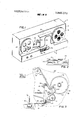
- FIG. 1 is a perspective view of an illustrative motion picture projector incorporating a control mechanism according to the present invention
- FIG. 2 is an enlarged elevational view of the selection plate and control lever of the projector as shown in FIG. 1 illustrating various operating positions;
- FIG. 3 is a sectional view taken along lines 3-3 of FIG. 1 showing a preferred embodiment of the present invention being positioned in the still mode 'of operation (shown in solid)'and the project position (shown in phantom);
- FIGS. 4 and 5 are sectional views similar to FIG. 3 showing the device positioned for fast forward and rewind modes of operation, respectively;
- FIG. 6 is a sectional view along line 66 of FIG. 5 showing greater detail of portions of the preferred embodiment of the present invention as illustrated in FIG.
- the illustrative projector 10 comprises a box-like housing 12 for the various internal components hereinafter described.
- a pair of spaced filmreel spindles l4 and 16 project from the housing to removably support the respective film supply and take-up reels 18 and 20 in a common plane at the opposite ends of one side of housing 12.
- Housing 12 includes a portion 22 that projects into the plane between the reels I8 and 20.
- a projection lens 24 projects from housing portion 22 and the optical axis of the lens is oriented to direct light from a lamp (not shown) onto a mirror 23.
- a slot in housing portion 22 defines a film path 26 which extends between the two reels, between the lamp and the projection lens 24 and through a film gate (not shown) therebetween, and past a film advancing mechanism (not shown) that is located along the film path within housing portion '22.
- the movement of the film along path 26 is controlled by the operator moving a selection lever 30 along a generally H shaped opening or slot 27 in the face plate '28 to the off," still, project, rewind or fast forward" positions which are identified upon the enlarged face plate depicted in FIG. 2.
- Movement of the selection lever 30 to the various operating positions affects the spindle control mechanism of the present invention as will be discussed in greater detail and also controls other projection linkage (not shown) which has been described in detail in the before-mentioned commonly assigned copending U.S. patent application Ser. No. 382,621, entitled, CON- TROL MECHANISM FOR A WEB TRANSPORTING DEVICE filedon even-m herewith in the name of .Donald 0. Easterly, and US. patent application Ser. 1 No. 382,636, entitled, PROJECTOR FUNCTION CONTROL MECHANISM filedon even date herewith in the names of Donald 0. Easterly et al. Asbest shown in FIG.
- the film reel spindle 14 is. rotatably supported by a frame plate 40 which is carried by the projector casing 12. Secured to spindle 14 is 'a circular drum 42 having a projecting peripheral-lip 44 that defines a cylindrical internal,
- frame plate 40 Also supported by frame plate 40 is an idler pulley 52 and a drive pulley 50.
- a continuous elastic belt 54 is trained aroundpulley 52 and is driven in a clockwise direction as viewed in the drawings by drive pulley 50 through conventional drive means as schematically indicated in FIG. 3.
- a control plate '56 is pivotally mounted to the frame plate 40. by a pivot stud 58 received in an arcuate slot 60in theplate.
- Control plate 56 includes an extension 62 which supports a friction pad or brake shoe 64 as shown in FIG. 6 wherein it is in'position to be moved into contact with the braking surface 46 to brake or retard rotation of the drum42. Also supported by the control plate 56 is freely .rotatable idler roller 74 which is aligned for urging the belt'54 into engagement with the driving surface 48 of drum 42 as shown in FIG. 6
- selection lever 30 ment' of the shifting lever will. produce correspondingrod 72 and the control plate 56.
- selection 7 acts through a control rod 72 to alter the position ofthe operates with selection lever 30 such that lateral movelever 30 is positioned forstill mode of operation (the position shown in solid in FIG. 3)
- a spring 68 urges control plate 56in a counterclockwise direction about pivot stud58 thereby urging friction pad 64 to contact braking surface 46 such that rotation of drum 42 and spindle 14 is resisted and advancement of film from the supplyreel 18' is retarded.
- lever 30 acts through the'control rod 72 rotate or pivot control plate 56 in a counterclockwise direction about pivot stud 58.
- spring 68 urges the rotatable drive roller 74 into contact with astop member -76 which is-secured to frame plate 40.
- friction pad'64 to be removed from contact with the braking surface 46 and thus drum 42 and spindle 14 are free to rotate, permitting'the film to be removed from the supply reel 18.
- selection lever 30 is shown shifted to the rewind position wherein controlplate 5618' moved in a clockwise direction'about pivot stud 58 to swing idler roller 74 into contact with belt 54 and displace-the. belt into driving engagement with the external driving surface 48 on drum 42; The resulting frictionalengagement between belt 54 and driving surface 38 is effective to cause drum 42'and spindle 14 to be driven in acounterclockwise direction for rewinding film upon the film reel 18.
- selection lever 39 may be readily'moved between theplurality'of positions shown on the face plate 28 for positioning the control plate56 as illustrated in FIGS. 3 through 5, it should be noted that it is necessary to shift the lever 30 throughthestillposition before the projector is changedto another operating mode. Aspreviously mentioned, this results in the braking ofthe rotation of the spindle 14 thereby preventing the projector from exerting high tension forces upon thefilm which could cause stretching or breaking of the film when the projector was shifted between fast forward and reverse modesof operation, for example.
- the driving mechanismof the projector comprises an elastic belt 54' which cooperates with thedriving'surface 48 through idler roller 74
- other drivemeans which could directly-drive drum 42 by contacting-the external driving surface 48.
- idler roller 74 could be driven independently and be urged into contact with driving surface 48 by movement of the control plate 56fto the position as shown in FIG. 5;
- Amechanism for selectively driving and braking a rotatable spindle of a web transporting apparatus comprising:
- brake means movable into engagement with said drum member for braking said spindle
- d. means for supporting said .pulley and said brake means for conjoint movement between (1) a first position wherein said pulley positions said belt into engagement with said drum member for driving said spindle, (2) a second position wherein said brake means restrains said spindle from rotating, and (3) a third position wherein said belt and said brake means are disengaged from said drum member.
- a mechanism for selectively driving and braking a rotatable spindle of a web transporting apparatus comprising:
- first and second means selectively engageable and disengageable with said rotatable member, said first means for rotatably driving said spindle and said second means for braking rotation of said spindle;
- a plate adapted to support said first and second means, said plate being pivotally supported by said web transporting apparatus for selectively moving said first and second means between (1) a first po sition wherein said first means rotatably drives said spindle, (2) a second position wherein said second means restrains rotation of said spindle, and (3) a third position wherein said first and second means are ineffective to drive or restrain rotation of said spindle; and v v d. control means for selectively moving said plate between said first, second and third positions.
- a motion picture projector for transporting a received film strip comprising:
- a spindle supported by said frame, said spindle adapted to receive and rotatably support said film strip for winding and unwinding, said spindle including a generally cylindrical lip defining a first surface suitable for rotatablydriving said spindle and a second surface suitable for braking rotation of said spindle;
- drive means selectively movable into engagement with said first surface for rotatably driving said spindle
- brake means selectively movable into engagement with said second surface for braking the rotation of said spindle
- a control plate supported by said frame for supporting said drive means and said brake means, said control plate being movable for selectively moving said drive means and said brake means between (1) a first position wherein said drive means is in engagement with said first surface causing said spindle to be rotatably driven, (2) a second posi- 6 tion wherein said brake means is in engagement with said second surface to restrain said spindle from being rotated, and (3,) a third position wherein said drive and brake means from said surfaces; and
- control means supported by said frame, said control means .being coupled to said control plate for are disengaged moving said drive means and said brake means between said first, second and third positions.
- a drive belt disposed between said pulley and said first surface of said drum member, said drive belt being displaceable by said pulley to engage said first surface for rotatably driving said spindle;
- control means for cooperating with said control plateto move said control plate between l a first position wherein said pulley displaces said drive belt to engage said first surface of said drum member to rotatably drive said spindle, (2) a second position wherein said brake pad cooperates with said second surface of said drum member to brake rotation of said spindle, and (3) a third position wherein said pulley is ineffective to displace said belt intoengagement with said first surface and said brake pad is ineffective to cooperate with said second surface of said drum member and said spindle is .freely rotatable.
- a motion picture projector having a housing and a rotatable spindle for receiving a roll of film, the improvement comprising:
- a cylindrical drum member coupled to said spindle, said drum member defining a first'surface suitable for rotatably driving said spindle and a second surface suitable for braking rotation of said spindle;
- control plate which is generally triangular in shape having first, second and third points and having an arcuate opening in the central portion thereof for receiving said pivot stud such that said control plate is pivotally and slidably supported by said pivot ,stud;
- drive means movable by said control plate, said drive means including a pulley supported by said control plate near said second point, and a drive belt disposed between said pulley and said first surface of said drum member, said drive belt being displaceable by said pulley to engage said first surface of said drum member for rotatably driving said spindle;
- control means for cooperating with said third point of said control plate to move said control plate between (l) a first position wherein said pulley displaces said drive belt to engage said first surface of i said drum member to rotatably drive said spindle, (2) a second position wherein said brake pad cooperates with said second surface of said drum member to brake rotation of said spindle, and (3) a third position wherein said pulley is ineffective to displace said belt into engagement with said first surface and said brake pad is ineffective to cooperate with said second surface of said drum member and said spindle is freely rotatable.
- control means comprises a control rod coupled to said third point of said control plate and a selection lever'movably supported by said housing cooperates to move said control plate between said first, second and third positions.
- a mechanism for selectively driving and braking a rotatable spindle of a web transporting apparatus comprising:
- a rotatable member operatively coupled to the spindle of the apparatus
- said plate being selectively movable between (l) a first position wherein said driving means is positioned to cooperate with said rotatable member to rotatably drive said spindle, (2) a second position wherein said braking means is positioned to cooperate with said rotatable member to restrain rotation of said spindle and (3) a third position wherein said driving and said braking means are no longer positioned to cooperate with said rotatable member for driving or restraining'rotation of said spindle; and
- control means operatively coupled to said third portion of said plate for selectively moving said plate between said first, second and third positions.
Abstract
A mechanism for selectively controlling the mode of operation of the supply spindle of a motion picture projector or the like includes a drive member for rotatably driving the spindle and a brake member for preventing rotation of the spindle. The mechanism is selectively operative between, (1) a first position wherein the spindle is driven by the drive member to wind film onto a reel mounted on the spindle; (2) a second position wherein the brake member restrains the spindle from being driven such that the film reel is restrained from movement; and (3) a third position wherein the brake member and the drive member are disengaged from the spindle and do not influence the operation of the spindle, thereby permitting the spindle to freely rotate such that film can be readily removed from the reel.
Description
United States Patent [191 Day [541 SPINDLE CONTROL MECHANISM [75] Inventor: Donald Earl Day, Rochester, NY.
[73] Assignee: Eastman Kodak Company,
Rochester, NY.
221 Filed: July 25, 1973 [21] Appl. No.:382,620
[52] US. Cl 242/204, 242/205, 352/124,
352/166 [51] Int. Cl. G03b 1/00 [58] Field of Search 352/124, ,159, 1 57, 158,
[56] References Cited UNITED STATES PATENTS 2,946,585 7/1960 Rosenberg 242/201 Primary Examiner-MonroeiH. Hayes Attorney, Agent, or Firm-J. Morrow; William H. Kline DRIVE MEANS Oct. 22, 1974 5 7 ABSTRACT A mechanism for selectively controlling the mode of operation of the supply spindle of a motion picture projector or the like includes a drive member for rotatably driving the spindle and a brake member for preventing rotation of the spindle. The mechanism is selectively operative between, (1) a first position wherein the, spindle is driven by the drive member to wind film onto a reel mounted on the spindle; (2) a second position wherein the brake member restrains the spindle from being driven such that the film reel is restrained from movement; and (3) a third position wherein the brake member and the drive member are disengaged from the spindle and do not influence the operation of the spindle, thereby permitting the spindle to freely rotate such that film can be readily removed from the reel.
9 Claims, 6 Drawing Figures A 3.8430732 ME! 1!! 2 PATENTEDUCTZZIHM FAST FORWARD OFF (STILL PROJECT REWIND 30 DRIVE MEANS 3 I -1 SPINDLE CONTROL MECHANISM Reference is hereby made to commonly assigned U.S. patent applications Ser. No. 294,709, entitled,
I BACKGROUND OF THE INVENTION l/Field of the Invention The present invention relates to a control mechanism for web transporting apparatus and, more particularly, to an improved mechanism for controlling the mode of operation of a supply spindle of a motion picture projector.
2. Description of the Prior Art Various spindle control mechanisms are known for braking and driving spindles in web transporting apparatus. Generally, these me'chanisms'are very' complex and therefore expensive. The present invention, on the other hand,-'provides an in expensive, simple and highly reliable braking and driving mechanism for controlling the mode of operation of the supply spindle of a web transporting apparatus.
, necessity for expensive, complex braking and drive systems for the spindle of a web transporting apparatus by providing a simplified spindlecontrol mechanism.
which readily permits selective changes in the mode of operation of the spindle. Another object of theinvention is to provide abraking and drive mechanism which permits selection of the mode of operation of the spindle of a web transporting apparatusby means of a single manually movable function selector member.
A further object of the invention is to provide a positive and reliable spindle control mechanism which can be moved by a single control member to selectively cause the spindle to be braked anddriven or to permit the spindle to be freely rotatable. 1
Briefly, these and other related objects are realized in accordance with a preferred embodiment of the present invention by driving and braking means engageable with a rotatable spindle which supports a received web material for winding and unwinding, the driving and braking means being selectively moved by control means between (l)-a first position wherein the driving means is engaged with the spindle causing the spindle to be rotatably, driven from winding the web material; (2) a second position wherein the braking means restrains the spindle from being rotatably driven; and (3) a third position wherein said driving and braking means are disengaged from the spindle.
The invention and its objects and advantages will become apparent in the detailed description of the preferred embodiment presented below.
' Y BRIEF DESCRIPTION OF THE DRAWINGS In the detailed description of the preferred embodiment presented below, reference ismade to the accompanying drawings in which:
FIG. 1 is a perspective view of an illustrative motion picture projector incorporating a control mechanism according to the present invention;
FIG. 2 is an enlarged elevational view of the selection plate and control lever of the projector as shown in FIG. 1 illustrating various operating positions;
FIG. 3 is a sectional view taken along lines 3-3 of FIG. 1 showing a preferred embodiment of the present invention being positioned in the still mode 'of operation (shown in solid)'and the project position (shown in phantom);
FIGS. 4 and 5 are sectional views similar to FIG. 3 showing the device positioned for fast forward and rewind modes of operation, respectively; and
FIG. 6 is a sectional view along line 66 of FIG. 5 showing greater detail of portions of the preferred embodiment of the present invention as illustrated in FIG.
DESCRIPTION OF THE PREFERRED EMBODIMENT Because motion picture projectors and related apparatus are well known, the following description is directed in particular to the elements forming part of or cooperating directly with the present invention. Elements not specifically shown or described herein being understood to be selectable from those known in the art.
Referring first to FIG. 1 of the accompanying drawings, the illustrative projector 10 comprises a box-like housing 12 for the various internal components hereinafter described. A pair of spaced filmreel spindles l4 and 16 project from the housing to removably support the respective film supply and take- up reels 18 and 20 in a common plane at the opposite ends of one side of housing 12. Housing 12 includes a portion 22 that projects into the plane between the reels I8 and 20. A projection lens 24 projects from housing portion 22 and the optical axis of the lens is oriented to direct light from a lamp (not shown) onto a mirror 23. A slot in housing portion 22 defines a film path 26 which extends between the two reels, between the lamp and the projection lens 24 and through a film gate (not shown) therebetween, and past a film advancing mechanism (not shown) that is located along the film path within housing portion '22. The movement of the film along path 26 is controlled by the operator moving a selection lever 30 along a generally H shaped opening or slot 27 in the face plate '28 to the off," still, project, rewind or fast forward" positions which are identified upon the enlarged face plate depicted in FIG. 2. Movement of the selection lever 30 to the various operating positions affects the spindle control mechanism of the present invention as will be discussed in greater detail and also controls other projection linkage (not shown) which has been described in detail in the before-mentioned commonly assigned copending U.S. patent application Ser. No. 382,621, entitled, CON- TROL MECHANISM FOR A WEB TRANSPORTING DEVICE filedon even-m herewith in the name of .Donald 0. Easterly, and US. patent application Ser. 1 No. 382,636, entitled, PROJECTOR FUNCTION CONTROL MECHANISM filedon even date herewith in the names of Donald 0. Easterly et al. Asbest shown in FIG. 2, there are 'aplurality of downward extending protrusions suchas shown at 29 which are secured along the opening 27 and are effective to-positively maintain the. selection lever 30 in' the off, still, p oje u Referring now in detail to FIGS. 3 through 5., the film reel spindle 14 is. rotatably supported by a frame plate 40 which is carried by the projector casing 12. Secured to spindle 14 is 'a circular drum 42 having a projecting peripheral-lip 44 that defines a cylindrical internal,
braking surface 46 'and a cylindrical external driving surface 48. Also supported by frame plate 40 is an idler pulley 52 and a drive pulley 50. A continuous elastic belt 54 is trained aroundpulley 52 and is driven in a clockwise direction as viewed in the drawings by drive pulley 50 through conventional drive means as schematically indicated in FIG. 3.
A control plate '56 is pivotally mounted to the frame plate 40. by a pivot stud 58 received in an arcuate slot 60in theplate. Control plate 56 includes an extension 62 which supports a friction pad or brake shoe 64 as shown in FIG. 6 wherein it is in'position to be moved into contact with the braking surface 46 to brake or retard rotation of the drum42. Also supported by the control plate 56 is freely .rotatable idler roller 74 which is aligned for urging the belt'54 into engagement with the driving surface 48 of drum 42 as shown in FIG. 6
for rotatably driving thedrum 42 aswill be explained in detaillater.
r'ewiri'df or fast forward position once .the operator has moved'thelever to determine the desired mode of operation of the projector.
As shown in. FIGS. 3.through 5, selection lever 30 ment' of the shifting lever will. produce correspondingrod 72 and the control plate 56. When the selection 7 acts through a control rod 72 to alter the position ofthe operates with selection lever 30 such that lateral movelever 30 is positioned forstill mode of operation (the position shown in solid in FIG. 3), a spring 68 urges control plate 56in a counterclockwise direction about pivot stud58 thereby urging friction pad 64 to contact braking surface 46 such that rotation of drum 42 and spindle 14 is resisted and advancement of film from the supplyreel 18' is retarded. Once the selection lever 30 ving 27 in plate'28 (the position shown in phantom in FIG. 3)., to condition the projector for operation in its projection mode, lever 30 acts through the'control rod 72 rotate or pivot control plate 56 in a counterclockwise direction about pivot stud 58. As this occurs, spring 68 urges the rotatable drive roller 74 into contact with astop member -76 which is-secured to frame plate 40. Continued rotation of plate 56in the counterclockwisedirection about the axis of rotation of roller 74 causes friction pad'64 to be removed from contact with the braking surface 46 and thus drum 42 and spindle 14 are free to rotate, permitting'the film to be removed from the supply reel 18. v
Movement of theselection lever 30 in theopening 27 to the lower right hand portion of plate 28for effecting the fast forward mode. of operation results in. the control plate 56 being shifted to the FIG. 4 position wherein the left end of the arcuate slot 60 engages the pivot stud 58. Although the difference in the position of the control plate 56 between the project mode (in phantom'in FIG; 3) and the fast forward mode (shown zin FIG. 4) is slight, movement of the selection lever 30 to the fast forward mode also controls other mechanisms of the'projector as is described in greater detail in the aforementioned commonly assigned US. patent application Ser. Nos, 382,62l-and 382,636.
- Referring now in particular to FIG. 5, selection lever 30 is shown shifted to the rewind position wherein controlplate 5618' moved in a clockwise direction'about pivot stud 58 to swing idler roller 74 into contact with belt 54 and displace-the. belt into driving engagement with the external driving surface 48 on drum 42; The resulting frictionalengagement between belt 54 and driving surface 38 is effective to cause drum 42'and spindle 14 to be driven in acounterclockwise direction for rewinding film upon the film reel 18. I
While selection lever 39 may be readily'moved between theplurality'of positions shown on the face plate 28 for positioning the control plate56 as illustrated in FIGS. 3 through 5, it should be noted that it is necessary to shift the lever 30 throughthestillposition before the projector is changedto another operating mode. Aspreviously mentioned, this results in the braking ofthe rotation of the spindle 14 thereby preventing the projector from exerting high tension forces upon thefilm which could cause stretching or breaking of the film when the projector was shifted between fast forward and reverse modesof operation, for example.
Although in the preferred embodiment the driving mechanismof the projector comprises an elastic belt 54' which cooperates with thedriving'surface 48 through idler roller 74, it would also be possible to use other drivemeans which could directly-drive drum 42 by contacting-the external driving surface 48. For example, idler roller 74 could be driven independently and be urged into contact with driving surface 48 by movement of the control plate 56fto the position as shown in FIG. 5; Thus, it should be understood that while the invention has been described in detail with particular reference to a preferred embodiment thereofyv'ariations and modifications can be effected within the spirit and scope. of the invention.
1 Amechanism for selectively driving and braking a rotatable spindle of a web transporting apparatus, the mechanism comprising:
a. a cylindrical drum member operatively' coupled to I said spindle; b. drive means including a pulley and a belt, said belt being movable into engagement with said drum member for rotatably driving said spindle;
c. brake means movable into engagement with said drum member for braking said spindle; and
d. means for supporting said .pulley and said brake means for conjoint movement between (1) a first position wherein said pulley positions said belt into engagement with said drum member for driving said spindle, (2) a second position wherein said brake means restrains said spindle from rotating, and (3) a third position wherein said belt and said brake means are disengaged from said drum member.
2. The mechanism as set forth in claim 1 wherein said cylindrical drum member includes first and second surfaces which are engageable by said belt and said brake means, respectively.
3. The mechanism as set forth in claim 2 wherein said brake means includes a brake pad which is engageable with said second surface.
4. A mechanism for selectively driving and braking a rotatable spindle of a web transporting apparatus, the mechanism comprising:
a. a rotatable member operatively coupled to said spindle;
b. first and second means selectively engageable and disengageable with said rotatable member, said first means for rotatably driving said spindle and said second means for braking rotation of said spindle;
a plate adapted to support said first and second means, said plate being pivotally supported by said web transporting apparatus for selectively moving said first and second means between (1) a first po sition wherein said first means rotatably drives said spindle, (2) a second position wherein said second means restrains rotation of said spindle, and (3) a third position wherein said first and second means are ineffective to drive or restrain rotation of said spindle; and v v d. control means for selectively moving said plate between said first, second and third positions.
5. A motion picture projector for transporting a received film strip, said projector comprising:
a. a frame; 7 a
b. a spindle supported by said frame, said spindle adapted to receive and rotatably support said film strip for winding and unwinding, said spindle including a generally cylindrical lip defining a first surface suitable for rotatablydriving said spindle and a second surface suitable for braking rotation of said spindle;
c. drive means selectively movable into engagement with said first surface for rotatably driving said spindle;
d. brake means selectively movable into engagement with said second surface for braking the rotation of said spindle;
e. a control plate supported by said frame for supporting said drive means and said brake means, said control plate being movable for selectively moving said drive means and said brake means between (1) a first position wherein said drive means is in engagement with said first surface causing said spindle to be rotatably driven, (2) a second posi- 6 tion wherein said brake means is in engagement with said second surface to restrain said spindle from being rotated, and (3,) a third position wherein said drive and brake means from said surfaces; and
f. control means supported by said frame, said control means .being coupled to said control plate for are disengaged moving said drive means and said brake means between said first, second and third positions. 6. In a motion picture projector having a housing and a rotatable spindle for receiving a roll of film, the improvement comprising:
, a. a cylindrical drum member coupled to said spindle, said drum member defining a first surface suitable for rotatably driving said spindle and a second surface suitable for braking rotation of said spindle;
b. a control plate pivotably supported by said hous- 0. a pulley supported by said control plate;
d. a drive belt disposed between said pulley and said first surface of said drum member, said drive belt being displaceable by said pulley to engage said first surface for rotatably driving said spindle;
e. a brake pad supported by said control plate, said brake pad being adapted to cooperate with said second surface of said drum member to brake rotation of said spindle; and
f. control means for cooperating with said control plateto move said control plate between l a first position wherein said pulley displaces said drive belt to engage said first surface of said drum member to rotatably drive said spindle, (2) a second position wherein said brake pad cooperates with said second surface of said drum member to brake rotation of said spindle, and (3) a third position wherein said pulley is ineffective to displace said belt intoengagement with said first surface and said brake pad is ineffective to cooperate with said second surface of said drum member and said spindle is .freely rotatable.
7. In a motion picture projector having a housing and a rotatable spindle for receiving a roll of film, the improvement comprising:
a. a cylindrical drum member coupled to said spindle, said drum member defining a first'surface suitable for rotatably driving said spindle and a second surface suitable for braking rotation of said spindle;
b. a pivot stud supported by the housing;
c. a control plate which is generally triangular in shape having first, second and third points and having an arcuate opening in the central portion thereof for receiving said pivot stud such that said control plate is pivotally and slidably supported by said pivot ,stud;
d. drive means movable by said control plate, said drive means including a pulley supported by said control plate near said second point, and a drive belt disposed between said pulley and said first surface of said drum member, said drive belt being displaceable by said pulley to engage said first surface of said drum member for rotatably driving said spindle;
e. a brake pad supported by said control plate near said first point, said brake pad being adapted to cooperate with 'said second surface of said drum member to brake rotation of said spindle; and
f. control means for cooperating with said third point of said control plate to move said control plate between (l) a first position wherein said pulley displaces said drive belt to engage said first surface of i said drum member to rotatably drive said spindle, (2) a second position wherein said brake pad cooperates with said second surface of said drum member to brake rotation of said spindle, and (3) a third position wherein said pulley is ineffective to displace said belt into engagement with said first surface and said brake pad is ineffective to cooperate with said second surface of said drum member and said spindle is freely rotatable.
8. The improvement as set forth in claim 7 wherein said control means comprises a control rod coupled to said third point of said control plate and a selection lever'movably supported by said housing cooperates to move said control plate between said first, second and third positions.
9. A mechanism for selectively driving and braking a rotatable spindle of a web transporting apparatus, the mechanism comprising:
a. a rotatable member operatively coupled to the spindle of the apparatus;
b. driving and braking means for selectively cooperating with said rotatable member for driving or braking the rotation of the spindle of the web transporting apparatus;
being supported by saidvplate from said first portion and said brake means being supported by said plate at said second portion, said plate being selectively movable between (l) a first position wherein said driving means is positioned to cooperate with said rotatable member to rotatably drive said spindle, (2) a second position wherein said braking means is positioned to cooperate with said rotatable member to restrain rotation of said spindle and (3) a third position wherein said driving and said braking means are no longer positioned to cooperate with said rotatable member for driving or restraining'rotation of said spindle; and
d. control means operatively coupled to said third portion of said plate for selectively moving said plate between said first, second and third positions.
Claims (9)
1. A mechanism for selectively driving and braking a rotatable spindle of a web transporting apparatus, the mechanism comprising: a. a cylindrical drum member operatively coupled to said spindle; b. drive means including a pulley and a belt, said belt being movable into engagement with said drum member for rotatably driving said spindle; c. brake means movable into engagement with said drum member for braking said spindle; and d. means for supporting said pulley and said brake means for conjoint movement between (1) a first position wherein said pulley positions said belt into engagement with said drum member for driving said spindle, (2) a second position wherein said brake means restrains said spindle from rotating, and (3) a third position wherein said belt and said brake means are disengaged from said drum member.
2. The mechanism as set forth in claim 1 wherein said cylindrical drum member includes first and second surfaces which are engageable by said belt and said brake means, respectively.
3. The mechanism as set forth in claim 2 wherein said brake means includes a brake pad which is engageable with said second surface.
4. A mechanism for selectively driving and braking a rotatable spindle of a web transporting apparatus, the mechanism comprising: a. a rotatable member operatively coupled to said spindle; b. first and second means selectively engageable and disengageable with said rotatable member, said first means for rotatably driving said spindle and said second means for braking rotation of said spindle; c. a plate adapted to support said first and second means, said plate being pivotally supported by said web transporting apparatus for selectively moving said first and second means between (1) a first position wherein said first means rotatably drives said spindle, (2) a second position wherein said second means restrains rotation of said spindle, and (3) a third position wherein said first and second means are ineffective to drive or restrain rotation of said spindle; and d. control means for selectively moving said plate between said first, second and third positions.
5. A motion picture projector for transporting a received film strip, said projector comprising: a. a frame; b. a spindle supported by said frame, said spindle adapted to receive and rotatably support said film strip for winding and unwinding, said spindle including a generally cylindrical lip defining a first surface suitable for rotatably driving said spindle and a second surface suitable for braking rotation of said spindle; c. drive means selectively movable into engagement with said first surface for rotatably driving said spindle; d. brake means selectively movable into engagement with said second surface for braking the rotation of said spindle; e. a control plate supported by said frame for supporting said drive means and said brake means, said control plate being movable for selectively moving said drive means and said brake means between (1) a first position wherein said drive means is in engagement with said first surface causing said spindle to be rotatably driven, (2) a second position wherein said brake means is in engagement with said second surface to restrain said spindle from being rotated, and (3) a third position wherein said drive and brake means are disengaged from said surfaces; and f. control means supported by said frame, said control means being coupled to said control plate for moving said drive means and said brake means between said first, second and third positions.
6. In a motion picture projector having a housing and a rotatable spindle for receiving a roll of film, the improvement comprising: a. a cylindrical drum member coupled to said spindle, said drum member defining a first surface suitable for rotatably driving said spindle and a second surface suitable for braking rotation of said spindle; b. a control plate pivotably supported by said housing; c. a pulley supported by said control plate; d. a drive belt disposed between said pulley and said first surface of said drum member, said drive belt being displaceable by said pulley to engage said first surface for rotatably driving said spindle; e. a brake pad supported by said control plate, said brake pad being adapted to cooperate with said second surface of said drum member to brake rotation of said spindle; and f. control means for cooperating with said control plate to move said control plate between (1) a first position wherein said pulley displaces said drive belt to engage said first surface of said drum member to rotatably drive said spindle, (2) a second position wherein said brake pad cooperates with said second surface of said drum member to brake rotation of said spindle, and (3) a third position wherein said pulley is ineffective to displace said belt into engagement with said first surface and said brake pad is ineffective to cooperate with said second surface of said drum member and said spindle is freely rotatable.
7. In a motion picture projector having a housing and a rotatable spindle for receiving a roll of film, the improvement comprising: a. a cylindrical drum member coupled to said spindle, said drum member defining a first surface suitable for rotatably driving said spindle and a second surface suitable for braking rotation of said spindle; b. a pivot stud supported by the housing; c. a control plate which is generally triangular in shape having first, second and third points and having an arcuate opening in the central portion thereof for receiving said pivot stud such that said control plate is pivotally and slidably supported by said pivot stud; d. drive means movable by said control plate, said drive means including a pulley supported by said control plate near said second point, and a drive belt disposed betweeN said pulley and said first surface of said drum member, said drive belt being displaceable by said pulley to engage said first surface of said drum member for rotatably driving said spindle; e. a brake pad supported by said control plate near said first point, said brake pad being adapted to cooperate with said second surface of said drum member to brake rotation of said spindle; and f. control means for cooperating with said third point of said control plate to move said control plate between (1) a first position wherein said pulley displaces said drive belt to engage said first surface of said drum member to rotatably drive said spindle, (2) a second position wherein said brake pad cooperates with said second surface of said drum member to brake rotation of said spindle, and (3) a third position wherein said pulley is ineffective to displace said belt into engagement with said first surface and said brake pad is ineffective to cooperate with said second surface of said drum member and said spindle is freely rotatable.
8. The improvement as set forth in claim 7 wherein said control means comprises a control rod coupled to said third point of said control plate and a selection lever movably supported by said housing cooperates to move said control plate between said first, second and third positions.
9. A mechanism for selectively driving and braking a rotatable spindle of a web transporting apparatus, the mechanism comprising: a. a rotatable member operatively coupled to the spindle of the apparatus; b. driving and braking means for selectively cooperating with said rotatable member for driving or braking the rotation of the spindle of the web transporting apparatus; c. a plate having first, second and third portions arranged in a triangular fashion, said drive means being supported by said plate from said first portion and said brake means being supported by said plate at said second portion, said plate being selectively movable between (1) a first position wherein said driving means is positioned to cooperate with said rotatable member to rotatably drive said spindle, (2) a second position wherein said braking means is positioned to cooperate with said rotatable member to restrain rotation of said spindle and (3) a third position wherein said driving and said braking means are no longer positioned to cooperate with said rotatable member for driving or restraining rotation of said spindle; and d. control means operatively coupled to said third portion of said plate for selectively moving said plate between said first, second and third positions.
Priority Applications (6)
| Application Number | Priority Date | Filing Date | Title |
|---|---|---|---|
| US00382620A US3843073A (en) | 1973-07-25 | 1973-07-25 | Spindle control mechanism |
| GB31870/74A GB1479303A (en) | 1973-07-25 | 1974-07-18 | Web transport control mechanism |
| JP49084066A JPS5055328A (en) | 1973-07-25 | 1974-07-22 | |
| FR7425429A FR2238943A1 (en) | 1973-07-25 | 1974-07-23 | |
| DE2435678A DE2435678A1 (en) | 1973-07-25 | 1974-07-24 | RUNNING IMAGE PROJECTOR |
| AT611774A ATA611774A (en) | 1973-07-25 | 1974-07-25 | CONTROL MECHANISM FOR TAPE TREADMILLS |
Applications Claiming Priority (1)
| Application Number | Priority Date | Filing Date | Title |
|---|---|---|---|
| US00382620A US3843073A (en) | 1973-07-25 | 1973-07-25 | Spindle control mechanism |
Publications (1)
| Publication Number | Publication Date |
|---|---|
| US3843073A true US3843073A (en) | 1974-10-22 |
Family
ID=23509760
Family Applications (1)
| Application Number | Title | Priority Date | Filing Date |
|---|---|---|---|
| US00382620A Expired - Lifetime US3843073A (en) | 1973-07-25 | 1973-07-25 | Spindle control mechanism |
Country Status (6)
| Country | Link |
|---|---|
| US (1) | US3843073A (en) |
| JP (1) | JPS5055328A (en) |
| AT (1) | ATA611774A (en) |
| DE (1) | DE2435678A1 (en) |
| FR (1) | FR2238943A1 (en) |
| GB (1) | GB1479303A (en) |
Cited By (2)
| Publication number | Priority date | Publication date | Assignee | Title |
|---|---|---|---|---|
| US4101097A (en) * | 1977-02-18 | 1978-07-18 | Bell & Howell Company | Drive control apparatus for motion picture projector |
| US5546143A (en) * | 1993-06-21 | 1996-08-13 | Sony Corporation | Recording device and projecting device for motion picture film |
Families Citing this family (1)
| Publication number | Priority date | Publication date | Assignee | Title |
|---|---|---|---|---|
| JPH0410590Y2 (en) * | 1984-12-30 | 1992-03-16 |
-
1973
- 1973-07-25 US US00382620A patent/US3843073A/en not_active Expired - Lifetime
-
1974
- 1974-07-18 GB GB31870/74A patent/GB1479303A/en not_active Expired
- 1974-07-22 JP JP49084066A patent/JPS5055328A/ja active Pending
- 1974-07-23 FR FR7425429A patent/FR2238943A1/fr not_active Withdrawn
- 1974-07-24 DE DE2435678A patent/DE2435678A1/en active Pending
- 1974-07-25 AT AT611774A patent/ATA611774A/en not_active Application Discontinuation
Cited By (2)
| Publication number | Priority date | Publication date | Assignee | Title |
|---|---|---|---|---|
| US4101097A (en) * | 1977-02-18 | 1978-07-18 | Bell & Howell Company | Drive control apparatus for motion picture projector |
| US5546143A (en) * | 1993-06-21 | 1996-08-13 | Sony Corporation | Recording device and projecting device for motion picture film |
Also Published As
| Publication number | Publication date |
|---|---|
| ATA611774A (en) | 1977-10-15 |
| FR2238943A1 (en) | 1975-02-21 |
| JPS5055328A (en) | 1975-05-15 |
| DE2435678A1 (en) | 1975-02-06 |
| GB1479303A (en) | 1977-07-13 |
Similar Documents
| Publication | Publication Date | Title |
|---|---|---|
| US3597056A (en) | Film movement equalizing device for a motion picture sound projector | |
| GB1390783A (en) | Motion picture projector | |
| US3558028A (en) | Control device for self-threading motion picture projector | |
| US3843073A (en) | Spindle control mechanism | |
| US3479940A (en) | Automatic film advancing and rewinding system | |
| GB1254705A (en) | Strip handling mechanism, and cinematographic projector incorporating the same | |
| US3694060A (en) | Motion-pictures projection device | |
| GB1287804A (en) | Cinematographic apparatus including mechanism for removing leading end of film roll from a spool | |
| US3724777A (en) | Motion picture projector apparatus | |
| US3614022A (en) | Projector for automatically threading, rewinding, and indexing a plurality of film spools and a magazine | |
| US2911849A (en) | Reversible drive mechanism | |
| US3481662A (en) | Film handling mechanism for a moving picture projector | |
| US3888573A (en) | Control mechanism for a web transporting device | |
| US3439981A (en) | Motion-picture projector | |
| US3609022A (en) | Motion picture film projector | |
| US3719335A (en) | Automatic film rewinding device for small movie projectors | |
| US3857633A (en) | Projector function control mechanism | |
| US3300155A (en) | Automatic rewinding mechanism for film or the like | |
| US3643896A (en) | Device for switching between film advance and film rewind in movie projectors | |
| US3630467A (en) | Automatic film-rewinding device for projector | |
| US2464135A (en) | Motion-picture projector film takeup and rewind mechanism | |
| US3731891A (en) | Web material feeding apparatus | |
| US3771745A (en) | Film feed mechanism for moving the film in normal and reverse directions | |
| US3506345A (en) | Self-threading motion picture projector | |
| US3689008A (en) | Device for adjusting a web-advancing mechanism |