US3837289A - Conveyor - Google Patents
Conveyor Download PDFInfo
- Publication number
- US3837289A US3837289A US00326045A US32604573A US3837289A US 3837289 A US3837289 A US 3837289A US 00326045 A US00326045 A US 00326045A US 32604573 A US32604573 A US 32604573A US 3837289 A US3837289 A US 3837289A
- Authority
- US
- United States
- Prior art keywords
- carrier
- pusher
- cam
- engageable
- control member
- Prior art date
- Legal status (The legal status is an assumption and is not a legal conclusion. Google has not performed a legal analysis and makes no representation as to the accuracy of the status listed.)
- Expired - Lifetime
Links
- 239000000969 carrier Substances 0.000 claims abstract description 25
- 230000001105 regulatory effect Effects 0.000 claims description 2
- 230000000712 assembly Effects 0.000 description 6
- 238000000429 assembly Methods 0.000 description 6
- 238000010276 construction Methods 0.000 description 3
- 230000001276 controlling effect Effects 0.000 description 2
- 241000212384 Bifora Species 0.000 description 1
- 239000003795 chemical substances by application Substances 0.000 description 1
- 238000009434 installation Methods 0.000 description 1
- 230000000717 retained effect Effects 0.000 description 1
- 230000001360 synchronised effect Effects 0.000 description 1
- 239000002023 wood Substances 0.000 description 1
Images


Classifications
-
- B—PERFORMING OPERATIONS; TRANSPORTING
- B65—CONVEYING; PACKING; STORING; HANDLING THIN OR FILAMENTARY MATERIAL
- B65G—TRANSPORT OR STORAGE DEVICES, e.g. CONVEYORS FOR LOADING OR TIPPING, SHOP CONVEYOR SYSTEMS OR PNEUMATIC TUBE CONVEYORS
- B65G19/00—Conveyors comprising an impeller or a series of impellers carried by an endless traction element and arranged to move articles or materials over a supporting surface or underlying material, e.g. endless scraper conveyors
- B65G19/02—Conveyors comprising an impeller or a series of impellers carried by an endless traction element and arranged to move articles or materials over a supporting surface or underlying material, e.g. endless scraper conveyors for articles, e.g. for containers
Definitions
- ABSTRACT A conveyor for forwarding carriers along a support, the carriers being engaged by pusher members attached to an endless driven chain supported on a track adjacent to the carrier support.
- Each pusher member is pivotally mounted and is associated with a pivoted control member located forwardly of the pusher member and connected thereto by a link, the two members being normally urged to positions in which the pusher member is drivingly engageable with a carrier and the control member is engageable with an object such as a preceding carrier overtaken by the control member, such engagement resulting in movement of the pusher member to a non-driving position and enabling carriers to be stopped and accumulated.
- a cam follower secured to the control member is selectively engageable with movable cam tracks.
- One type of cam track is arranged to produce movement of the pusher member to non-driving position when engaged by the cam follower and is combined with an abutment for stopping the carrier being driven by the pusher member.
- a second type of cam track when engaged by the cam follower, causes the control member to be converted into an auxiliary pusher by preventing pivotal movement of the control member in response to engagement with a carrier.
- This invention relates to a conveyor including a support providing a path along which carriers are movable in a forwarding direction, each carrier being drivingly engageable by one of a plurality of pusher members carried by a chain supported on a track located adjacent to the carrier support.
- Each pusher member is pivotally mounted on a bracket attached to the chain and is movable between driving and non-driving positions relative to a carrier.
- the invention is directed to the problem of providing, in a conveyor of the above type, a construction which permits carriers to be selectively stopped and accumulated and which also permits carriers to be positively propelled, as at a zone where the carriers are transferred to a work station or into a position where they are engageable by pusher members of another driven chain.
- a control member is associated with each pusher member, the control member being pivotally mounted in advance of the pusher member with relation to the forwarding direction of carrier movement, and the pusher memberis connected to the control member by suitable means such as a link.
- the control and pusher members are normally urged to an operative relation with a carrier in which the pusher member is drivingly engageable therewith and the control member is engageable with an object such as a preceding carrier overtaken by the control member, the control member being movable from an operative to an inoperative position in response to such engagement and causing the connecting means to move the pusher member to non-driving position.
- a cam follower is operatively associated with the pusher and control members, and cam means mounted adjacent to a portion of the chain supporting track is engageable by the cam follower, the cam means defining a position of the cam follower corresponding to one of the operative and inoperative positions of the control member.
- the cam means comprises a cam track, positionable in engageable and non-engageable relation with the cam follower, and arranged to define a position of the cam follower when engaged thereby which corresponds to the inoperative position of the control member, a carrier stopping member being associated with the cam track.
- the cam means comprises a cam track arranged to define a position of the cam follower which corresponds to the operative position of the control member, the control member being capable of acting as an auxiliary pusher for the transfer of a carrier when the operative position of the control member is so defined.
- This cam track may also be selectively positionable in engageable and nonengageable relation with the cam follower.
- a preferred form of connecting means between the pusher and control members comprises a crank formed on each of these members and a link connected to each crank by a pivot, one of the link pivots forming the center pivot of a toggle-type release, and abutment means defining a locked position of the center pivot when the pusher and control members are in the operative relation with a carrier, the pusher and control members being movable out of the operative relation only when the center pivot moves from the locked position towards a released position.
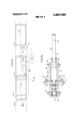
- FIG. I is a sectional side elevation of a portion of a conveyor constructed in accordance with the invention and showing a pusher assembly attached to a chain, the pusher assembly including a pusher member in driving engagement with a carrier;
- FIG. 2 is an enlarged top plan view of the pusher assembly shown in FIG. 1;
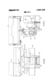
- FIG. 3 is a plan view schematically illustrating a transfer zone of a conveyor constructed in accordance with the invention.
- FIG. 4 is a side elevation of a portion of the conveyor showing a carrier stopping device
- FIG. 5 is a transverse sectional elevation of the structure shown in FIG. 4;
- FIG. 6 is a side elevation of a portion of the conveyor showing an arrangement for positively propelling a carrier
- FIG. 7 is a transverse sectional elevation of the structure shown in FIG. 6.
- a conveyor constructed in accordance with the invention includes a support 10 formed by a pair of parallel, transversely spaced angle section members 11 and 12, each having a horizontal supporting surface 13 and a vertical guiding surface 14 equipped with wear strips 15, the support 10 providing a path along which carriers 16 are movable in a forwarding direction 18.
- Each carrier 16 is drivingly engageable by one of a plurality of pusher members 20 carried by a driven chain 22 supported on a track 24 located adjacent to the carrier support 10.
- Each pusher member 20 is part of an assembly 26 which includes a bracket 27 attached to the chain 22, the bracket 27 having a pair of side plates 28 and 29 (FIG. 2) supporting a transverse pin 30 on which the pusher member 20 is pivotally mounted.
- the assembly 26 also includes a control member 32 pivotally mounted on a pin 33 carried by the bracket 27 and located in advance of the pusher member 20 with relation to the forwarding direction 18 of carrier movement.
- Means in the form of a link 34 connects the pusher member 20 to the control member 32 for movement thereby, the link 34 being attached to a pivot 35 on a crank portion 36 of the pusher member and to a pivot 37 on a crank portion 38 of the control member, one of the link pivots 37 thereby forming the center pivot of a toggle-type release.
- a spring 40 mounted on the control member pivot 33, as best shown in FIG. 2, provides a means for normally urging the control and pusher members to an operative relation with a carrier, shown in FIG. I.
- a driving face 42 on the pusher member 20 is engageable with an abutment 43 on the carrier formed by a recess 44 in the bottom thereof, and a portion 46 of the control member projects into the path of carrier travel defined by the support and is engageable with an object such as a preceding carrier overtaken by the control member, the control member being movable from an operative to an inoperative position in response to such engagement and causing the connecting means 34 to move the pusher member to non-driving position.
- a roller 47 is mounted on the outer end of the portion 46 of the control member to reduce the frictional resistance resulting from such engagement.
- the connecting means or link 34 is in turn positioned so that the center pivot 37 is in an overcenter or locked position relative to the link pivot 35 and the control member pivot 33.
- This locked position of the center pivot 37 is defined by abutment means, and the pusher and control members are movable out of the operative relation with a carrier only when the center pivot 37 moves from the locked position towards a released position. As shown in FIGS.
- slots 48 and 49 are formed in the side plates 28 and 29 of the bracket 27 and the center pivot 37 is provided with portions which project through these slots, the abutment means being formed by one end of each slot and being engaged by rollers 50 and 51 mounted on the projecting portions of the center pivot 37.
- This toggle-type of release retains the pusher member 20 in driving position, resists pivotal movement of the pusher member 20 resulting from the driving reaction between the pusher member and a carrier 16, and permits pivotal movement of the control member 32 in response to engagement with an object in its path of travel such as a preceding carrier.
- Such pivotal movement of the control member 32 moves the center pivot 37 out of the overcenter or locked position and results in positively moving the pusher member to non-driving position, with relatively little force on the control member being required to overcome any frictional resistance between the driving face 42 of the pusher mem ber and a. carrier engaged thereby. Since this toggletype of release does not permit pivotal movement of v the control member if engaged by a faster moving carrier, the control member 32 can perform a holdback function on such a carrier.
- a cam follower is operatively associated with the pusher and control members, and preferably consists of a pair of rollers 54 and 55 mounted on the projecting portions of the center pivot 37 outwardly of the side plates 28 and 29 of the bracket 27 so that one of these rollers 54 or 55 is engageable by cam means mounted adjacent to a portion of the chain supporting track 24 on either side thereof.
- cam means are illustrated in FIGS. 4 and 5 and in FIGS. 6 and 7, and are described below.
- the cam means forms part of a device for stopping a carrier 16 and comprises a cam track 62 engageable by the cam follower roller 55 and arranged to define a position thereof corresponding to the inoperative position of the control member 32.
- the cam track 62 includes a forwardly and downwardly inclined portion 63 which when engaged by the roller 55, moves the center pivot 37 out of the locked position and in consequence moves the pusher member 20 to nondriving position and the control member 32 to inoperative position, the control and pusher members being retained in these positions while the roller 55 is in engagement with a horizontal portion 64 of the cam track 62.
- the cam track 62 is positionable in engageable and non-engageable relation with the cam follower, the cam track being attached to supporting means 66 formed by an arm 67 mounted on a pivot 68 extending longitudinally of the chain supporting track 24 and connected to suitable actuating means 69 such as the rotary solenoid 70 attached to a fixed plate 71.
- a carrier stopping member 72 associated with the cam track 62 is mounted on a transverse pivot 73 carried by the arm 67 and is provided with a counterweighted portion 74 which normally urges the member 72 to an obstructing position relative to a carrier.
- This pivotal mounting of the stopping member 72 enables it to move to a nonobstructing position in the event the solenoid 70 is energized to place the cam track 62 in engageable relation with the cam follower at a time when the stopping member 72 would engage the underside of a carrier.
- the solenoid 70 is de-energized, the weight of the cam track 62 and stopping member 72 carried by the arm 67 biases the arm to the'non-engageable position of the cam track relative to the cam follower.
- a second form of cam means 58 is shown in FIGS. 6 and 7, and comprises a cam track 76 arranged to define a position of the cam follower 55 corresponding to the operative position of the control member 32.
- the cam track 76 includes a horizontal portion 78, which when engaged by the cam follower 55, positively prevents movement of the center pivot 37 in a releasing direction, and as a result, the control member 32 is capable of driving engagement with a carrier 16 and of acting as an auxiliary pusher.
- the cam track 76 is positionable in engageable and nonengageable relation with the cam follower 55, the cam track being mounted on supporting means 80 formed by an arm 81 mounted on a pivot 82 extending longitudinally of the chain supporting track 24 and connected to actuating means 85 in the form of a rotary solenoid 86 carried by a fixed plate 87.
- the cam track 76 may be mounted in fixed relation with a portion of the chain supporting track 24.
- the stopping device 60 of FIGS. 4 and 5 may of course be installed along any portion of the conveyor where it is desired to halt the forwarding movement of carriers, and any following carrier approaching a stopped carrier will also stop and accumulate as the control member 32 of the pusher assembly 26 driving the following carrier overtakes the stopped carrier and is moved to inoperative position as a result of engagement therewith.
- the cam track 76 of FIGS. 6 and 7 may be installed in fixed relation with the carrier support so as to be engageable by the cam followers of all pusher assemblies traversing this section of the conveyor.
- FIG. 3 Ways in which the cam means 58 can be employed for transferring carriers of a conveyor are schematically illustrated in FIG. 3, wherein the carrier support 10 is represented by a pair of parallel solid lines and a broken line represents the path of the chain track 24 and pusher assemblies 26 which diverges from the path of the support 10 at a transfer zone 88, the pusher assemblies 26 traveling along the track 24 in the direction of the arrow 18.
- the stop device 60 and cam track 62 of FIGS. 4 and 5 is installed adjacent to a portion of the track 24 in advance of the transfer zone and is represented by a circle; and, the positionable cam track 76 of FIGS. 6 and 7 is installed along the diverging portion of the chain track 24 at the transfer zone.
- a carrier be advanced into a position such as is indicated by the leading end of the carrier 16-4 in order to perform, for example, a loading or an unloading operation.
- a carrier be advanced into a position where it can be engaged by a pusher of an independently driven chain, traveling in a path indicated by the broken line 24A and in the direction of the arrow 18A.
- the first type of transfer operation proceeds in the following manner.
- the first carrier to approach the transfer zone 88 is advanced to the position indicated by the leading end of the carrier 16-2 where the propelling pusher loses engagement due to the divergence of the chain supporting track 24.
- the solenoids 70 and 86 controlling the positions of the stop device 60 and cam track 76, respectively, are then energized to move the cam track 76 and the cam track 62 of the stop device 60 into engageable relation with the cam followers.
- next approaching pusher assembly is propelling a carrier
- that carrier is stopped by the device 60 at the position indicated by the carrier 16-1 and this pusher assembly continues on with its cam follower then engaging the cam track 76.
- Such engagement converts the control member 32 of this pusher assembly into an auxiliary pusher which engages the rear of the carrier 16-2 and advances this carrier into the position indicated by the carrier 16-3.
- the carrier is then advanced to the 16-4 position by auxiliary equipment (not shown), the cam track 76 is deactivated, and the stop device 60 is also de-activated to permit a following carrier to be advanced to the position of the carrier 16-2.
- the cam track 76 is re-activated so that the following carrier is advanced to the 16-3 position.
- Control means 90 regulate the movement of the cam tracks 62 and 76 between their engageable and nonengageable positions relative to the cam followers in response to the advance of a carrier through the transfer zone.
- Suitable sensing devices such as limit switches for detecting the various carrier positions and controlling the operation of the solenoids 70 and 86 have not been shown, since the use of such devices and control circuits in which they are incorporated are within the capabilities of those skilled in the art.
- the transfer operation is one at which carriers are advanced into a position for engagement by receiving pusher assemblies traveling on the path 24A
- the operation is somewhat similar. Again assuming that there are no carriers present on the support 10 and that the stop device 60 and the cam track 76 are both positioned in non-engageable relation with the cam followers of pusher assemblies, the first carrier to approach the transfer zone 88 is advanced into the position of the carrier 16-2 where engagement with a forwarding pusher is lost. The cam track 76 and stop device are then actuated. As a result, the carrier at the position 16-2 is engaged by the control member 32 of the next pusher assembly, acting as an auxiliary pusher, and advanced into the position of the carrier 16-3 to await engagement by a receiving pusher. When this takes place, for example, when the carrier has been moved ahead by a receiving pusher to the position of the carrier 16-4, the cam track 76 and stop device 60 can be deactivated to initiate the transfer of a following carrier.
- a conveyor including a support providing a path along which carriers are movable in a forwarding direction, each carrier being drivingly engageable by one of a plurality of pusher members carried by a chain supported on a track located adjacent to the carrier support, each pusher member being pivotally mounted on a bracket attached to the chain and being movable between driving and non-driving positions relative to a carrier; wherein the improvement comprises:
- control member pivotally mounted on the bracket in advance of the pusher member with relation to the forwarding direction of carrier movement
- control and pusher members normally urging the control and pusher members to an operative relation with a carrier in which the pusher member is drivingly engageable therewith and the control member is engageable with an object such as a preceding carrier overtaken by the control member, the control member being movable from an operative to an inoperative position in response to such engagement and causing the connecting means to move the pusher member to nondriving position;
- cam follower operatively associated with the pusher and control members
- cam means mounted adjacent to a portion of the chain supporting track and engageable by the cam follower, the cam means including a cam track arranged to define a position of the cam follower corresponding to the operative position of the control member, the control member being capable of positive engagement with a carrier when the operative position of the control member is so defined.
- cam means further includes second a cam track arranged to define a position of the cam follower corresponding to the inoperative position of the control member.
- cam means includes means supporting the cam track for movement between engageable and non-engageable positions relative to the cam follower, and actuating means for moving the cam track between said positions.
- a conveyor according to claim 8 wherein the means supporting the cam track comprises an arm, pivot means supporting the arm on an axis extending longitudinally of the chain supporting track, and the arm is biased to the non-engageable position of the cam track relative to the cam follower.
- a conveyor including a support providing a path along which carriers are movable in a forwarding direction, each carrier being drivingly engageable by one of a plurality of pusher members carried by a chain supported on a track located adjacent to the carrier support, each pusher member being pivotally mounted on a bracket attached to the chain and being movable between driving and non-driving positions relative to a carrier; wherein the improvement comprises:
- control member pivotally mounted on the bracket in advance of the pusher member with relation to the forwarding direction of carrier movement
- control and pusher members normally urging the control and pusher members to an operative relation with a carrier in which the pusher member is drivingly engageable therewith and the control member is engageable with an object such as a preceding carrier overtaken by the control member, the control member being movable from an operative to an inoperative position in response to such engagement and causing the connecting means to move the pusher member to nondriving position;
- cam follower operatively associated with the pusher and control members; cam means mounted adjacent to a portion of the chain supporting track and engageable by the cam follower, the cam means defining a position of the cam follower corresponding to one of the operative and inoperative positions of the control member;
- the cam means includes a first cam track at the transfer zone arranged to define a position of the cam follower corresponding to the operative position of the control member, the control member being capable of acting as an auxiliary pusher when the operative position of the control member is so defined.
- cam means further includes a second cam track mounted in advance of the first cam track with relation to the forwarding direction of carrier movement and arranged to define a position of the cam follower corresponding to the inoperative position of the control member, the second cam track being selectively positionable in engageable and non-engageable relation with the cam follower and forming part of a carrier stop device.
- a conveyor according to claim 1 wherein the means connecting the pusher member to the control member comprises a crank on each of the pusher and control members and a link connected to each crank by a pivot, one of the link pivots forming the center pivot of a toggle-type release, and abutment means defining a locked position of the center pivot when the pusher and control members are in the operative relation with a carrier.
- a conveyor including a support along which carriers are movable in a forwarding direction, each carrier being drivingly engageable by one of a plurality of pusher members carried by a chain supported on a track located adjacent to the carrier support, wherein:
- each pusher member forms part of a pusher assembly
- a bracket attached to the chain the pusher member being pivotally mounted on the bracket, a control member pivotally mounted on the bracket in advance of the pusher member with relation to the forwarding direction of carrier movement, means connecting the pusher member to the control member for movement thereby, and means normally urging the control and pusher members to an operative relation with a carrier in which the pusher member is drivingly engageable therewith and the control member is engageable with an object such as a preceding carrier overtaken by the control member
- the connecting means includes a crank on each of the pusher and control members and a link connected to each crank by a pivot, one of the link pivots forming the center pivot of a toggle-type release;
- abutment means defines a locked position of the center pivot when the pusher and control members are in the operative relation with a carrier, the pusher and control members being movable out of the operative relation only when the center pivot moves from the locked position towards a released position.
- a conveyor according to claim 19 further including cam means mounted adjacent to a portion of the chain supporting track and engageable by the cam follower, the cam means defining a position of the cam follower corresponding to one of the locked and the released positions of the center pivot.
- a conveyor according to claim 20 wherein the rier stopping member is associated with the cam track. l l zg ggg UNITED STATES PATENT oFmcE CERTIFICATE OF CGRRECTWN patent 3837289 Dated September 24, I974 lnventofls) Edward F. Marshman, Bruno D. Warmann fied that error appears in the above-identified patent It is cer ti t are hereby corrected as shown below:
Abstract
A conveyor for forwarding carriers along a support, the carriers being engaged by pusher members attached to an endless driven chain supported on a track adjacent to the carrier support. Each pusher member is pivotally mounted and is associated with a pivoted control member located forwardly of the pusher member and connected thereto by a link, the two members being normally urged to positions in which the pusher member is drivingly engageable with a carrier and the control member is engageable with an object such as a preceding carrier overtaken by the control member, such engagement resulting in movement of the pusher member to a non-driving position and enabling carriers to be stopped and accumulated. A cam follower secured to the control member is selectively engageable with movable cam tracks. One type of cam track is arranged to produce movement of the pusher member to non-driving position when engaged by the cam follower and is combined with an abutment for stopping the carrier being driven by the pusher member. A second type of cam track, when engaged by the cam follower, causes the control member to be converted into an auxiliary pusher by preventing pivotal movement of the control member in response to engagement with a carrier.
Description
United States Patent 1 Marshman et al.
[451 Sept. 24, 1974 CONVEYOR [75] Inventors: Edward F. 'Marshman, South Lyon;
Bruno D. Warmann, Livonia, both of Mich.
[73] Assignee: Jervis B. Webb Company, Detroit,
Mich.
[22] Filed: Jan. 23, 1973 [21] Appl. No.: 326,045
[52] US. Cl. 104/172 B, 104/96 [51] Int. Cl. B65g 17/42 [58] Field of Search 104/172 B, 172 C, 172 S, 104/96, 249, 250, 251
[56] References Cited UNITED STATES PATENTS 3,099,228 7/1963 Lingg 104/172 S 3,434,431 3/1969 Dehne 104/172 S 3,437,054 4/1969 Bishop 104/249 3,559,586 2/1971 Follrath 104/172 S 3,623,538 11/1971 Wakabayashi 104/172 S FOREIGN PATENTS OR APPLICATIONS 250,031 5/1969 U.S.S.R. 104/172 B Primary ExaminerM. Henson Wood, Jr. Assistant ExaminerRobert Saifer Attorney, Agent, or FirmFarley, Forster and Farley [5 7 ABSTRACT A conveyor for forwarding carriers along a support, the carriers being engaged by pusher members attached to an endless driven chain supported on a track adjacent to the carrier support. Each pusher member is pivotally mounted and is associated with a pivoted control member located forwardly of the pusher member and connected thereto by a link, the two members being normally urged to positions in which the pusher member is drivingly engageable with a carrier and the control member is engageable with an object such as a preceding carrier overtaken by the control member, such engagement resulting in movement of the pusher member to a non-driving position and enabling carriers to be stopped and accumulated. A cam follower secured to the control member is selectively engageable with movable cam tracks. One type of cam track is arranged to produce movement of the pusher member to non-driving position when engaged by the cam follower and is combined with an abutment for stopping the carrier being driven by the pusher member. A second type of cam track, when engaged by the cam follower, causes the control member to be converted into an auxiliary pusher by preventing pivotal movement of the control member in response to engagement with a carrier.
23 Claims, 7 Drawing Figures CONVEYOR SUMMARY OF THE INVENTION This invention relates to a conveyor including a support providing a path along which carriers are movable in a forwarding direction, each carrier being drivingly engageable by one of a plurality of pusher members carried by a chain supported on a track located adjacent to the carrier support. Each pusher member is pivotally mounted on a bracket attached to the chain and is movable between driving and non-driving positions relative to a carrier.
The invention is directed to the problem of providing, in a conveyor of the above type, a construction which permits carriers to be selectively stopped and accumulated and which also permits carriers to be positively propelled, as at a zone where the carriers are transferred to a work station or into a position where they are engageable by pusher members of another driven chain.
In the construction of the invention, a control member is associated with each pusher member, the control member being pivotally mounted in advance of the pusher member with relation to the forwarding direction of carrier movement, and the pusher memberis connected to the control member by suitable means such as a link. The control and pusher members are normally urged to an operative relation with a carrier in which the pusher member is drivingly engageable therewith and the control member is engageable with an object such as a preceding carrier overtaken by the control member, the control member being movable from an operative to an inoperative position in response to such engagement and causing the connecting means to move the pusher member to non-driving position. A cam follower is operatively associated with the pusher and control members, and cam means mounted adjacent to a portion of the chain supporting track is engageable by the cam follower, the cam means defining a position of the cam follower corresponding to one of the operative and inoperative positions of the control member.
For the selective stopping of carriers, the cam means comprises a cam track, positionable in engageable and non-engageable relation with the cam follower, and arranged to define a position of the cam follower when engaged thereby which corresponds to the inoperative position of the control member, a carrier stopping member being associated with the cam track.
For the positive propulsion of a carrier, the cam means comprises a cam track arranged to define a position of the cam follower which corresponds to the operative position of the control member, the control member being capable of acting as an auxiliary pusher for the transfer of a carrier when the operative position of the control member is so defined. This cam track may also be selectively positionable in engageable and nonengageable relation with the cam follower.
A preferred form of connecting means between the pusher and control members comprises a crank formed on each of these members and a link connected to each crank by a pivot, one of the link pivots forming the center pivot of a toggle-type release, and abutment means defining a locked position of the center pivot when the pusher and control members are in the operative relation with a carrier, the pusher and control members being movable out of the operative relation only when the center pivot moves from the locked position towards a released position.
Other features and advantages of the invention will appear from the following description of the embodiment thereof shown in the accompanying drawings, which illustrate the invention as applied to a conveyor for propelling carriers in the form of trays or pallets.
DESCRIPTION OF THE DRAWINGS FIG. I is a sectional side elevation of a portion of a conveyor constructed in accordance with the invention and showing a pusher assembly attached to a chain, the pusher assembly including a pusher member in driving engagement with a carrier;
FIG. 2 is an enlarged top plan view of the pusher assembly shown in FIG. 1;
FIG. 3 is a plan view schematically illustrating a transfer zone of a conveyor constructed in accordance with the invention;
FIG. 4 is a side elevation of a portion of the conveyor showing a carrier stopping device;
FIG. 5 is a transverse sectional elevation of the structure shown in FIG. 4;
FIG. 6 is a side elevation of a portion of the conveyor showing an arrangement for positively propelling a carrier; and,
FIG. 7 is a transverse sectional elevation of the structure shown in FIG. 6.
DESCRIPTION OF THE PREFERRED EMBODIMENT As shown in FIGS. 1 and 5, a conveyor constructed in accordance with the invention includes a support 10 formed by a pair of parallel, transversely spaced angle section members 11 and 12, each having a horizontal supporting surface 13 and a vertical guiding surface 14 equipped with wear strips 15, the support 10 providing a path along which carriers 16 are movable in a forwarding direction 18. Each carrier 16 is drivingly engageable by one of a plurality of pusher members 20 carried by a driven chain 22 supported on a track 24 located adjacent to the carrier support 10. 7
Each pusher member 20 is part of an assembly 26 which includes a bracket 27 attached to the chain 22, the bracket 27 having a pair of side plates 28 and 29 (FIG. 2) supporting a transverse pin 30 on which the pusher member 20 is pivotally mounted. The assembly 26 also includes a control member 32 pivotally mounted on a pin 33 carried by the bracket 27 and located in advance of the pusher member 20 with relation to the forwarding direction 18 of carrier movement.
Means in the form of a link 34 connects the pusher member 20 to the control member 32 for movement thereby, the link 34 being attached to a pivot 35 on a crank portion 36 of the pusher member and to a pivot 37 on a crank portion 38 of the control member, one of the link pivots 37 thereby forming the center pivot of a toggle-type release.
A spring 40, mounted on the control member pivot 33, as best shown in FIG. 2, provides a means for normally urging the control and pusher members to an operative relation with a carrier, shown in FIG. I. In this operative relation of the control and pusher members with a carrier, a driving face 42 on the pusher member 20 is engageable with an abutment 43 on the carrier formed by a recess 44 in the bottom thereof, and a portion 46 of the control member projects into the path of carrier travel defined by the support and is engageable with an object such as a preceding carrier overtaken by the control member, the control member being movable from an operative to an inoperative position in response to such engagement and causing the connecting means 34 to move the pusher member to non-driving position. A roller 47 is mounted on the outer end of the portion 46 of the control member to reduce the frictional resistance resulting from such engagement.
When the pusher and control members are in the operative relation with a carrier, as shown in FIG. 1 and described above, the connecting means or link 34 is in turn positioned so that the center pivot 37 is in an overcenter or locked position relative to the link pivot 35 and the control member pivot 33. This locked position of the center pivot 37 is defined by abutment means, and the pusher and control members are movable out of the operative relation with a carrier only when the center pivot 37 moves from the locked position towards a released position. As shown in FIGS. 1 and 2, slots 48 and 49 are formed in the side plates 28 and 29 of the bracket 27 and the center pivot 37 is provided with portions which project through these slots, the abutment means being formed by one end of each slot and being engaged by rollers 50 and 51 mounted on the projecting portions of the center pivot 37.
This toggle-type of release retains the pusher member 20 in driving position, resists pivotal movement of the pusher member 20 resulting from the driving reaction between the pusher member and a carrier 16, and permits pivotal movement of the control member 32 in response to engagement with an object in its path of travel such as a preceding carrier. Such pivotal movement of the control member 32 moves the center pivot 37 out of the overcenter or locked position and results in positively moving the pusher member to non-driving position, with relatively little force on the control member being required to overcome any frictional resistance between the driving face 42 of the pusher mem ber and a. carrier engaged thereby. Since this toggletype of release does not permit pivotal movement of v the control member if engaged by a faster moving carrier, the control member 32 can perform a holdback function on such a carrier.
A cam follower is operatively associated with the pusher and control members, and preferably consists of a pair of rollers 54 and 55 mounted on the projecting portions of the center pivot 37 outwardly of the side plates 28 and 29 of the bracket 27 so that one of these rollers 54 or 55 is engageable by cam means mounted adjacent to a portion of the chain supporting track 24 on either side thereof. Such cam means are illustrated in FIGS. 4 and 5 and in FIGS. 6 and 7, and are described below.
In FIGS. 4 and 5, the cam means, indicated generally by the reference 58, forms part of a device for stopping a carrier 16 and comprises a cam track 62 engageable by the cam follower roller 55 and arranged to define a position thereof corresponding to the inoperative position of the control member 32. The cam track 62 includes a forwardly and downwardly inclined portion 63 which when engaged by the roller 55, moves the center pivot 37 out of the locked position and in consequence moves the pusher member 20 to nondriving position and the control member 32 to inoperative position, the control and pusher members being retained in these positions while the roller 55 is in engagement with a horizontal portion 64 of the cam track 62.
The cam track 62 is positionable in engageable and non-engageable relation with the cam follower, the cam track being attached to supporting means 66 formed by an arm 67 mounted on a pivot 68 extending longitudinally of the chain supporting track 24 and connected to suitable actuating means 69 such as the rotary solenoid 70 attached to a fixed plate 71. A carrier stopping member 72 associated with the cam track 62 is mounted on a transverse pivot 73 carried by the arm 67 and is provided with a counterweighted portion 74 which normally urges the member 72 to an obstructing position relative to a carrier. This pivotal mounting of the stopping member 72 enables it to move to a nonobstructing position in the event the solenoid 70 is energized to place the cam track 62 in engageable relation with the cam follower at a time when the stopping member 72 would engage the underside of a carrier. When the solenoid 70 is de-energized, the weight of the cam track 62 and stopping member 72 carried by the arm 67 biases the arm to the'non-engageable position of the cam track relative to the cam follower.
A second form of cam means 58 is shown in FIGS. 6 and 7, and comprises a cam track 76 arranged to define a position of the cam follower 55 corresponding to the operative position of the control member 32. The cam track 76 includes a horizontal portion 78, which when engaged by the cam follower 55, positively prevents movement of the center pivot 37 in a releasing direction, and as a result, the control member 32 is capable of driving engagement with a carrier 16 and of acting as an auxiliary pusher. In the construction shown, the cam track 76 is positionable in engageable and nonengageable relation with the cam follower 55, the cam track being mounted on supporting means 80 formed by an arm 81 mounted on a pivot 82 extending longitudinally of the chain supporting track 24 and connected to actuating means 85 in the form of a rotary solenoid 86 carried by a fixed plate 87. Alternately, the cam track 76 may be mounted in fixed relation with a portion of the chain supporting track 24.
In the practice of the invention, the stopping device 60 of FIGS. 4 and 5 may of course be installed along any portion of the conveyor where it is desired to halt the forwarding movement of carriers, and any following carrier approaching a stopped carrier will also stop and accumulate as the control member 32 of the pusher assembly 26 driving the following carrier overtakes the stopped carrier and is moved to inoperative position as a result of engagement therewith. Along portions of a conveyor where it is desired that carriers be positively propelled, for example on an upwardly inclined section of the conveyor, the cam track 76 of FIGS. 6 and 7 may be installed in fixed relation with the carrier support so as to be engageable by the cam followers of all pusher assemblies traversing this section of the conveyor.
Ways in which the cam means 58 can be employed for transferring carriers of a conveyor are schematically illustrated in FIG. 3, wherein the carrier support 10 is represented by a pair of parallel solid lines and a broken line represents the path of the chain track 24 and pusher assemblies 26 which diverges from the path of the support 10 at a transfer zone 88, the pusher assemblies 26 traveling along the track 24 in the direction of the arrow 18. The stop device 60 and cam track 62 of FIGS. 4 and 5 is installed adjacent to a portion of the track 24 in advance of the transfer zone and is represented by a circle; and, the positionable cam track 76 of FIGS. 6 and 7 is installed along the diverging portion of the chain track 24 at the transfer zone.
Two types of transfer operations are illustrated. in one of these, it is desired that a carrier be advanced into a position such as is indicated by the leading end of the carrier 16-4 in order to perform, for example, a loading or an unloading operation. In the other form of transfer, it is desired that a carrier be advanced into a position where it can be engaged by a pusher of an independently driven chain, traveling in a path indicated by the broken line 24A and in the direction of the arrow 18A.
Assuming that there are no carriers present on the support and that the stop device 60 and cam track 76 are both positioned in non-engageable relation with' the cam followers of pusher assemblies, the first type of transfer operation proceeds in the following manner. The first carrier to approach the transfer zone 88 is advanced to the position indicated by the leading end of the carrier 16-2 where the propelling pusher loses engagement due to the divergence of the chain supporting track 24. The solenoids 70 and 86 controlling the positions of the stop device 60 and cam track 76, respectively, are then energized to move the cam track 76 and the cam track 62 of the stop device 60 into engageable relation with the cam followers. If the next approaching pusher assembly is propelling a carrier, that carrier is stopped by the device 60 at the position indicated by the carrier 16-1 and this pusher assembly continues on with its cam follower then engaging the cam track 76. Such engagement converts the control member 32 of this pusher assembly into an auxiliary pusher which engages the rear of the carrier 16-2 and advances this carrier into the position indicated by the carrier 16-3. The carrier is then advanced to the 16-4 position by auxiliary equipment (not shown), the cam track 76 is deactivated, and the stop device 60 is also de-activated to permit a following carrier to be advanced to the position of the carrier 16-2. When a carrier in the position of the carrier 16-4 is cleared or moved ahead, the cam track 76 is re-activated so that the following carrier is advanced to the 16-3 position.
Control means 90 regulate the movement of the cam tracks 62 and 76 between their engageable and nonengageable positions relative to the cam followers in response to the advance of a carrier through the transfer zone.
Suitable sensing devices such as limit switches for detecting the various carrier positions and controlling the operation of the solenoids 70 and 86 have not been shown, since the use of such devices and control circuits in which they are incorporated are within the capabilities of those skilled in the art.
Where the transfer operation is one at which carriers are advanced into a position for engagement by receiving pusher assemblies traveling on the path 24A, the operation is somewhat similar. Again assuming that there are no carriers present on the support 10 and that the stop device 60 and the cam track 76 are both positioned in non-engageable relation with the cam followers of pusher assemblies, the first carrier to approach the transfer zone 88 is advanced into the position of the carrier 16-2 where engagement with a forwarding pusher is lost. The cam track 76 and stop device are then actuated. As a result, the carrier at the position 16-2 is engaged by the control member 32 of the next pusher assembly, acting as an auxiliary pusher, and advanced into the position of the carrier 16-3 to await engagement by a receiving pusher. When this takes place, for example, when the carrier has been moved ahead by a receiving pusher to the position of the carrier 16-4, the cam track 76 and stop device 60 can be deactivated to initiate the transfer of a following carrier.
In the case of a conveyor installation where the chains driving the forward and receiving pushers are synchronized, it may not be necessary to employ a stop device 60 in advance of the transfer zone, or to control the position of the cam track 76.
We claim:
1. A conveyor including a support providing a path along which carriers are movable in a forwarding direction, each carrier being drivingly engageable by one of a plurality of pusher members carried by a chain supported on a track located adjacent to the carrier support, each pusher member being pivotally mounted on a bracket attached to the chain and being movable between driving and non-driving positions relative to a carrier; wherein the improvement comprises:
a control member pivotally mounted on the bracket in advance of the pusher member with relation to the forwarding direction of carrier movement;
means connecting the pusher member to the control member for movement thereby;
means normally urging the control and pusher members to an operative relation with a carrier in which the pusher member is drivingly engageable therewith and the control member is engageable with an object such as a preceding carrier overtaken by the control member, the control member being movable from an operative to an inoperative position in response to such engagement and causing the connecting means to move the pusher member to nondriving position;
a cam follower operatively associated with the pusher and control members;
and cam means mounted adjacent to a portion of the chain supporting track and engageable by the cam follower, the cam means including a cam track arranged to define a position of the cam follower corresponding to the operative position of the control member, the control member being capable of positive engagement with a carrier when the operative position of the control member is so defined.
2. A conveyor according to claim 1 wherein the portion of the chain supporting track adjacent to which the cam means is mounted is located at a transfer zone, the control member being capable of acting as an auxiliary pusher for the transfer of a carrier when the operative position of the control member is defined by engagement between the cam follower and the cam track.
3. A conveyor according to claim 2 wherein the cam track is positionable in engageable and non-engageable relation with the cam follower.
4. A conveyor according to claim 1 wherein the cam means further includes second a cam track arranged to define a position of the cam follower corresponding to the inoperative position of the control member.
5. A conveyor according to claim 4 wherein a carrier stopping member is associated with the second cam track.
6. A conveyor according to claim 5 wherein the second cam track is positionable in engageable and nonengageable relation with the cam follower.
7. A conveyor according to claim 6 wherein the carrier stopping member is movable relative to the second cam track between obstructing and non-obstructing positions relative to a carrier and is normally urged to the obstructing position.
8. A conveyor according to claim 1 wherein the cam means includes means supporting the cam track for movement between engageable and non-engageable positions relative to the cam follower, and actuating means for moving the cam track between said positions.
9. A conveyor according to claim 8 wherein the means supporting the cam track comprises an arm, pivot means supporting the arm on an axis extending longitudinally of the chain supporting track, and the arm is biased to the non-engageable position of the cam track relative to the cam follower.
10. A conveyor including a support providing a path along which carriers are movable in a forwarding direction, each carrier being drivingly engageable by one of a plurality of pusher members carried by a chain supported on a track located adjacent to the carrier support, each pusher member being pivotally mounted on a bracket attached to the chain and being movable between driving and non-driving positions relative to a carrier; wherein the improvement comprises:
a control member pivotally mounted on the bracket in advance of the pusher member with relation to the forwarding direction of carrier movement;
means connecting the pusher member to the control member for movement thereby;
means normally urging the control and pusher members to an operative relation with a carrier in which the pusher member is drivingly engageable therewith and the control member is engageable with an object such as a preceding carrier overtaken by the control member, the control member being movable from an operative to an inoperative position in response to such engagement and causing the connecting means to move the pusher member to nondriving position;
a cam follower operatively associated with the pusher and control members; cam means mounted adjacent to a portion of the chain supporting track and engageable by the cam follower, the cam means defining a position of the cam follower corresponding to one of the operative and inoperative positions of the control member;
a transfer zone at which the path of the chain supporting track diverges from the path of the carrier support, and the cam means includes a first cam track at the transfer zone arranged to define a position of the cam follower corresponding to the operative position of the control member, the control member being capable of acting as an auxiliary pusher when the operative position of the control member is so defined.
11. A conveyor according to claim 10 wherein the cam means further includes a second cam track mounted in advance of the first cam track with relation to the forwarding direction of carrier movement and arranged to define a position of the cam follower corresponding to the inoperative position of the control member, the second cam track being selectively positionable in engageable and non-engageable relation with the cam follower and forming part of a carrier stop device.
12. A conveyor according to claim 11 wherein the first cam track is movable between engageable and non-engageable positions relative to the cam follower, and control means for regulating the movement of the first and second cam tracks between such positions in response to the advance of a carrier through the transfer zone.
13. A conveyor according to claim 11 wherein the second cam track has a carrier stopping member operatively associated therewith and abuttingly engageable by a carrier when the second cam track is positioned in engageable relation with the cam follower.
14. A conveyor according to claim 1 wherein the means connecting the pusher member to the control member comprises a crank on each of the pusher and control members and a link connected to each crank by a pivot, one of the link pivots forming the center pivot of a toggle-type release, and abutment means defining a locked position of the center pivot when the pusher and control members are in the operative relation with a carrier.
15. A conveyor according to claim 14 wherein the cam follower is carried by the center pivot.
16. A conveyor including a support along which carriers are movable in a forwarding direction, each carrier being drivingly engageable by one of a plurality of pusher members carried by a chain supported on a track located adjacent to the carrier support, wherein:
each pusher member forms part of a pusher assembly comprising a bracket attached to the chain, the pusher member being pivotally mounted on the bracket, a control member pivotally mounted on the bracket in advance of the pusher member with relation to the forwarding direction of carrier movement, means connecting the pusher member to the control member for movement thereby, and means normally urging the control and pusher members to an operative relation with a carrier in which the pusher member is drivingly engageable therewith and the control member is engageable with an object such as a preceding carrier overtaken by the control member; the connecting means includes a crank on each of the pusher and control members and a link connected to each crank by a pivot, one of the link pivots forming the center pivot of a toggle-type release;
and abutment means defines a locked position of the center pivot when the pusher and control members are in the operative relation with a carrier, the pusher and control members being movable out of the operative relation only when the center pivot moves from the locked position towards a released position.
17. A conveyor according to claim 16 wherein the bracket includes a pair of side plates between which the pusher and control members are each pivotally mounted. a slot is formed in at least one of the side plates, and the center pivot is provided with a portion 18. A conveyor according to claim 17 wherein a cam follower is carried by the projecting portion of the center pivot.
19. A conveyor according to claim 16 wherein a cam follower is operatively associated with the pusher and control members.
20. A conveyor according to claim 19 further including cam means mounted adjacent to a portion of the chain supporting track and engageable by the cam follower, the cam means defining a position of the cam follower corresponding to one of the locked and the released positions of the center pivot.
21. A conveyor according to claim 20 wherein the rier stopping member is associated with the cam track. =l l zg ggg UNITED STATES PATENT oFmcE CERTIFICATE OF CGRRECTWN patent 3837289 Dated September 24, I974 lnventofls) Edward F. Marshman, Bruno D. Warmann fied that error appears in the above-identified patent It is cer ti t are hereby corrected as shown below:
and that said Letters Paten Column 6, Claim 4, line 66 change "second a to read a second Signed and sealed this 24th day of December 197% (SEAL) Attest:
c, MARSHALL DANN Commissioner of Patents J MCCOY M. GIBSON JR. Attesting Officer
Claims (23)
1. A conveyor including a support providing a path along which carriers are movable in a forwarding direction, each carrier being drivingly engageable by one of a plurality of pusher members carried by a chain supported on a track located adjacent to the carrier support, each pusher member being pivotally mounted on a bracket attached to the chain and being movable between driving and non-driving positions relative to a carrier; wherein the improvement compriseS: a control member pivotally mounted on the bracket in advance of the pusher member with relation to the forwarding direction of carrier movement; means connecting the pusher member to the control member for movement thereby; means normally urging the control and pusher members to an operative relation with a carrier in which the pusher member is drivingly engageable therewith and the control member is engageable with an object such as a preceding carrier overtaken by the control member, the control member being movable from an operative to an inoperative position in response to such engagement and causing the connecting means to move the pusher member to non-driving position; a cam follower operatively associated with the pusher and control members; and cam means mounted adjacent to a portion of the chain supporting track and engageable by the cam follower, the cam means including a cam track arranged to define a position of the cam follower corresponding to the operative position of the control member, the control member being capable of positive engagement with a carrier when the operative position of the control member is so defined.
2. A conveyor according to claim 1 wherein the portion of the chain supporting track adjacent to which the cam means is mounted is located at a transfer zone, the control member being capable of acting as an auxiliary pusher for the transfer of a carrier when the operative position of the control member is defined by engagement between the cam follower and the cam track.
3. A conveyor according to claim 2 wherein the cam track is positionable in engageable and non-engageable relation with the cam follower.
4. A conveyor according to claim 1 wherein the cam means further includes second a cam track arranged to define a position of the cam follower corresponding to the inoperative position of the control member.
5. A conveyor according to claim 4 wherein a carrier stopping member is associated with the second cam track.
6. A conveyor according to claim 5 wherein the second cam track is positionable in engageable and non-engageable relation with the cam follower.
7. A conveyor according to claim 6 wherein the carrier stopping member is movable relative to the second cam track between obstructing and non-obstructing positions relative to a carrier and is normally urged to the obstructing position.
8. A conveyor according to claim 1 wherein the cam means includes means supporting the cam track for movement between engageable and non-engageable positions relative to the cam follower, and actuating means for moving the cam track between said positions.
9. A conveyor according to claim 8 wherein the means supporting the cam track comprises an arm, pivot means supporting the arm on an axis extending longitudinally of the chain supporting track, and the arm is biased to the non-engageable position of the cam track relative to the cam follower.
10. A conveyor including a support providing a path along which carriers are movable in a forwarding direction, each carrier being drivingly engageable by one of a plurality of pusher members carried by a chain supported on a track located adjacent to the carrier support, each pusher member being pivotally mounted on a bracket attached to the chain and being movable between driving and non-driving positions relative to a carrier; wherein the improvement comprises: a control member pivotally mounted on the bracket in advance of the pusher member with relation to the forwarding direction of carrier movement; means connecting the pusher member to the control member for movement thereby; means normally urging the control and pusher members to an operative relation with a carrier in which the pusher member is drivingly engageable therewith and the control member is engageable with an object such as a preceding carrier overtaken by the control member, the control member being movable from an operative to an inoperative position in response to such engagement and causing the connecting means to move the pusher member to non-driving position; a cam follower operatively associated with the pusher and control members; cam means mounted adjacent to a portion of the chain supporting track and engageable by the cam follower, the cam means defining a position of the cam follower corresponding to one of the operative and inoperative positions of the control member; a transfer zone at which the path of the chain supporting track diverges from the path of the carrier support, and the cam means includes a first cam track at the transfer zone arranged to define a position of the cam follower corresponding to the operative position of the control member, the control member being capable of acting as an auxiliary pusher when the operative position of the control member is so defined.
11. A conveyor according to claim 10 wherein the cam means further includes a second cam track mounted in advance of the first cam track with relation to the forwarding direction of carrier movement and arranged to define a position of the cam follower corresponding to the inoperative position of the control member, the second cam track being selectively positionable in engageable and non-engageable relation with the cam follower and forming part of a carrier stop device.
12. A conveyor according to claim 11 wherein the first cam track is movable between engageable and non-engageable positions relative to the cam follower, and control means for regulating the movement of the first and second cam tracks between such positions in response to the advance of a carrier through the transfer zone.
13. A conveyor according to claim 11 wherein the second cam track has a carrier stopping member operatively associated therewith and abuttingly engageable by a carrier when the second cam track is positioned in engageable relation with the cam follower.
14. A conveyor according to claim 1 wherein the means connecting the pusher member to the control member comprises a crank on each of the pusher and control members and a link connected to each crank by a pivot, one of the link pivots forming the center pivot of a toggle-type release, and abutment means defining a locked position of the center pivot when the pusher and control members are in the operative relation with a carrier.
15. A conveyor according to claim 14 wherein the cam follower is carried by the center pivot.
16. A conveyor including a support along which carriers are movable in a forwarding direction, each carrier being drivingly engageable by one of a plurality of pusher members carried by a chain supported on a track located adjacent to the carrier support, wherein: each pusher member forms part of a pusher assembly comprising a bracket attached to the chain, the pusher member being pivotally mounted on the bracket, a control member pivotally mounted on the bracket in advance of the pusher member with relation to the forwarding direction of carrier movement, means connecting the pusher member to the control member for movement thereby, and means normally urging the control and pusher members to an operative relation with a carrier in which the pusher member is drivingly engageable therewith and the control member is engageable with an object such as a preceding carrier overtaken by the control member; the connecting means includes a crank on each of the pusher and control members and a link connected to each crank by a pivot, one of the link pivots forming the center pivot of a toggle-type release; and abutment means defines a locked position of the center pivot when the pusher and control members are in the operative relation with a carrier, the pusher and control members being movable out of the operative relation only when the center pivot moves from the locked position towards a released position.
17. A conveyor according to claim 16 wherein the bracket includes a pair of side plates between which the pusher and control members are each pivotally mounted, a slot is formEd in at least one of the side plates, and the center pivot is provided with a portion projecting into the slot, the abutment means being formed by one end of the slot.
18. A conveyor according to claim 17 wherein a cam follower is carried by the projecting portion of the center pivot.
19. A conveyor according to claim 16 wherein a cam follower is operatively associated with the pusher and control members.
20. A conveyor according to claim 19 further including cam means mounted adjacent to a portion of the chain supporting track and engageable by the cam follower, the cam means defining a position of the cam follower corresponding to one of the locked and the released positions of the center pivot.
21. A conveyor according to claim 20 wherein the cam means comprises a cam track arranged to define a position of the cam follower corresponding to the locked position of the center pivot, the control member being capable of positive engagement with a carrier when the position of the cam follower is so defined.
22. A conveyor according to claim 20 wherein the cam means comprises a cam track arranged to define a position of the cam follower corresponding to the released position of the center pivot.
23. A conveyor according to claim 22 wherein a carrier stopping member is associated with the cam track.
Priority Applications (2)
| Application Number | Priority Date | Filing Date | Title |
|---|---|---|---|
| US00326045A US3837289A (en) | 1973-01-23 | 1973-01-23 | Conveyor |
| BE144269A BE814963A (en) | 1973-01-23 | 1974-05-13 | CONVEYOR |
Applications Claiming Priority (1)
| Application Number | Priority Date | Filing Date | Title |
|---|---|---|---|
| US00326045A US3837289A (en) | 1973-01-23 | 1973-01-23 | Conveyor |
Publications (1)
| Publication Number | Publication Date |
|---|---|
| US3837289A true US3837289A (en) | 1974-09-24 |
Family
ID=23270595
Family Applications (1)
| Application Number | Title | Priority Date | Filing Date |
|---|---|---|---|
| US00326045A Expired - Lifetime US3837289A (en) | 1973-01-23 | 1973-01-23 | Conveyor |
Country Status (2)
| Country | Link |
|---|---|
| US (1) | US3837289A (en) |
| BE (1) | BE814963A (en) |
Cited By (8)
| Publication number | Priority date | Publication date | Assignee | Title |
|---|---|---|---|---|
| US4004680A (en) * | 1975-09-22 | 1977-01-25 | Warmann Bruno D | Conveyor pusher mechanism |
| US4885997A (en) * | 1985-07-23 | 1989-12-12 | Nakanishi Metal Works Co., Ltd. | Power-and-free conveyor |
| US4898099A (en) * | 1986-11-04 | 1990-02-06 | Mid-West Conveyor Co., Inc. | Positive retraction trolley stop for power and free conveyors |
| US6161483A (en) * | 1998-07-17 | 2000-12-19 | Conveyor Technology Group | Accumulator mechanism for detaching trolleys from drive chains in power and free conveyor system |
| US6669011B2 (en) | 2001-05-17 | 2003-12-30 | Joh. Winklhofer & Sohne Gmbh Und Co. Kg | Conveying system |
| US20070205859A1 (en) * | 2006-02-17 | 2007-09-06 | Pflow Industries, Inc. | Shopping cart conveyor with gated access |
| US20110147164A1 (en) * | 2009-12-23 | 2011-06-23 | Pflow Industries, Inc. | Shopping cart conveyor with gate assembly |
| NL2013029B1 (en) * | 2014-06-19 | 2016-07-06 | Jonge Poerink Conveyors B V | Conveyor, conveyor track and conveyor tray. |
Citations (6)
| Publication number | Priority date | Publication date | Assignee | Title |
|---|---|---|---|---|
| SU250031A1 (en) * | С. Н. чко | SUSPENDED PUSH CONVEYOR CARGO TRUCK | ||
| US3099228A (en) * | 1961-10-12 | 1963-07-30 | Lingg Gerhard | Transport and storage arrangement for carriers |
| US3434431A (en) * | 1965-12-27 | 1969-03-25 | Webb Co Jervis B | Stop for conveyor carriers |
| US3437054A (en) * | 1966-10-20 | 1969-04-08 | Mechanical Handling Sys Inc | Power and free conveyor system |
| US3559586A (en) * | 1968-11-29 | 1971-02-02 | Rapistan Inc | Retracting push-rod assembly for conveyors |
| US3623538A (en) * | 1968-05-30 | 1971-11-30 | Nakanishi Metal Works Co | Power and free conveyor system |
-
1973
- 1973-01-23 US US00326045A patent/US3837289A/en not_active Expired - Lifetime
-
1974
- 1974-05-13 BE BE144269A patent/BE814963A/en unknown
Patent Citations (6)
| Publication number | Priority date | Publication date | Assignee | Title |
|---|---|---|---|---|
| SU250031A1 (en) * | С. Н. чко | SUSPENDED PUSH CONVEYOR CARGO TRUCK | ||
| US3099228A (en) * | 1961-10-12 | 1963-07-30 | Lingg Gerhard | Transport and storage arrangement for carriers |
| US3434431A (en) * | 1965-12-27 | 1969-03-25 | Webb Co Jervis B | Stop for conveyor carriers |
| US3437054A (en) * | 1966-10-20 | 1969-04-08 | Mechanical Handling Sys Inc | Power and free conveyor system |
| US3623538A (en) * | 1968-05-30 | 1971-11-30 | Nakanishi Metal Works Co | Power and free conveyor system |
| US3559586A (en) * | 1968-11-29 | 1971-02-02 | Rapistan Inc | Retracting push-rod assembly for conveyors |
Cited By (10)
| Publication number | Priority date | Publication date | Assignee | Title |
|---|---|---|---|---|
| US4004680A (en) * | 1975-09-22 | 1977-01-25 | Warmann Bruno D | Conveyor pusher mechanism |
| US4885997A (en) * | 1985-07-23 | 1989-12-12 | Nakanishi Metal Works Co., Ltd. | Power-and-free conveyor |
| US4898099A (en) * | 1986-11-04 | 1990-02-06 | Mid-West Conveyor Co., Inc. | Positive retraction trolley stop for power and free conveyors |
| US6161483A (en) * | 1998-07-17 | 2000-12-19 | Conveyor Technology Group | Accumulator mechanism for detaching trolleys from drive chains in power and free conveyor system |
| US6669011B2 (en) | 2001-05-17 | 2003-12-30 | Joh. Winklhofer & Sohne Gmbh Und Co. Kg | Conveying system |
| US20070205859A1 (en) * | 2006-02-17 | 2007-09-06 | Pflow Industries, Inc. | Shopping cart conveyor with gated access |
| US7453358B2 (en) * | 2006-02-17 | 2008-11-18 | Pflow Industries, Inc. | Shopping cart conveyor with gated access |
| US20110147164A1 (en) * | 2009-12-23 | 2011-06-23 | Pflow Industries, Inc. | Shopping cart conveyor with gate assembly |
| US8328003B2 (en) | 2009-12-23 | 2012-12-11 | Pflow Industries, Inc. | Shopping cart conveyor with gate assembly |
| NL2013029B1 (en) * | 2014-06-19 | 2016-07-06 | Jonge Poerink Conveyors B V | Conveyor, conveyor track and conveyor tray. |
Also Published As
| Publication number | Publication date |
|---|---|
| BE814963A (en) | 1974-09-02 |
Similar Documents
| Publication | Publication Date | Title |
|---|---|---|
| US3044416A (en) | Conveyor trolley with releasable driving dog | |
| US3451352A (en) | Conveyor carrier with selectively operable dogs | |
| US3229645A (en) | Power and free conveyors | |
| US3837289A (en) | Conveyor | |
| US3995561A (en) | Conveyor stop mechanism | |
| US3559585A (en) | Power and free conveyor | |
| US3799327A (en) | Conveyor system and dog | |
| US2161388A (en) | Overhead carrier system | |
| US3523504A (en) | Power and free conveyor | |
| US3434431A (en) | Stop for conveyor carriers | |
| US4004680A (en) | Conveyor pusher mechanism | |
| US2575396A (en) | Trolley propelling device for conveyer systems | |
| GB1416034A (en) | Conveyor systems | |
| US3690269A (en) | Conveyor systems | |
| US3477390A (en) | Accumulating conveyor system | |
| US3464364A (en) | Conveyor switch | |
| JPS6411502B2 (en) | ||
| US3662873A (en) | Conveyor system | |
| US3742861A (en) | Transfer conveyors | |
| US3437054A (en) | Power and free conveyor system | |
| US3640226A (en) | Conveyor system | |
| US3744432A (en) | Trolley diverter | |
| US3347171A (en) | Carrier stop and track hangar for power and free conveyors | |
| US3800710A (en) | Stopping stations of a power and free conveyor | |
| US3741126A (en) | Suspended conveyor system |