US382679A - barber - Google Patents
barber Download PDFInfo
- Publication number
- US382679A US382679A US382679DA US382679A US 382679 A US382679 A US 382679A US 382679D A US382679D A US 382679DA US 382679 A US382679 A US 382679A
- Authority
- US
- United States
- Prior art keywords
- arms
- platform
- tread
- pivoted
- links
- Prior art date
- Legal status (The legal status is an assumption and is not a legal conclusion. Google has not performed a legal analysis and makes no representation as to the accuracy of the status listed.)
- Expired - Lifetime
Links
- 210000003414 Extremities Anatomy 0.000 description 6
- 102000004726 Connectin Human genes 0.000 description 2
- 108010002947 Connectin Proteins 0.000 description 2
- 241000282619 Hylobates lar Species 0.000 description 2
- 238000010276 construction Methods 0.000 description 2
Images

Classifications
-
- B—PERFORMING OPERATIONS; TRANSPORTING
- B61—RAILWAYS
- B61D—BODY DETAILS OR KINDS OF RAILWAY VEHICLES
- B61D23/00—Construction of steps for railway vehicles
- B61D23/02—Folding steps for railway vehicles, e.g. hand or mechanically actuated
Definitions
- a further object is to provide steps of the character named which when folded will form a continuation of the car-platform, with a foot-
- the invention consists in so pivoting the treads and risers of the steps to operating arms .and bars that when folded they will be adjusted edge to edge and will form a continuation or extension of the platform, with the exception of the lowest tread, which will assume a vertical position at the outer edge of the said extension, and thus constitute a guard to prevent persons from falling from the plat,
- A designates the platform, having the openings B B at each end, in which the steps operate, it being my desire to bring the steps in both the lowered and raised positions within the line of the outside'of the car.
- This frame is braced by fthinclined braces D D, which depend the length of the car, and F F representswing- 5 5 ing arms which are mounted at their upper ends on this rod.
- Similar arms,'G G are pivoted at their upper ends to the sides of the openings BB at a distance from the upper. ends of the arms F Fequal to the width of a tread of the proposed steps.
- the arms G are about twice the length of the arms F, andtheir centers are connectedto the lower ends of the said arms Fby the links HH. 7 f
- I I represent swinging arms, which are pivoted at one end to the vertical bars a 0 near their upper ends, and they are divided at their other ends to formthe forks K K.
- the arms k k which comprise the said forks, are connected at their lower ends by the bars L, which have inward-extending flanges Z, for a purpose to be hereinafter explained.
- the link N is connected at the outer end to aninten mediate point of the arm I, and at a point near the inner end'to the extremity of the angle -too arm M, which is on the lower end of the arm G.
- the upper pivoted ends of the arms G and I are in the same vertical line; but the ends of the arms G are above those of the arms I, whereas the distance from the pivoted end of the arm G to the point where the link is pivoted thereto is about the same as the distance from the pivoted end of the arm Ito the point where the other end of the said link is pivoted thereto.
- 0 represents the top tread, which is secured to the horizontal flanges h on the links H.
- P represents thesecond tread,which is simi lar to the tread O, and is secured to the flanges n on thelinks N; and Q represents the bottom tread, which is secured to the flanges Z on the bars L.
- 0 represents the top riser, which is secured at the ends to the swinging arms F F
- P represents a riser which is secured to the arms G G below the point where the ends of the links H are pivoted thereto.
- the rear edge of the tread 0 projects ashortdistancebeyond the ends of the links H, and therefore when the said links assume their horizontal position in the closed position of the step the rear edge of the said tread will exactly meet the front edge of the riser O, which is brought to the horizontal position by the armsF F, and their upper surfaces will be flush with each other and with the platform A.
- the links N are (as before described) turned over or reversed,'and therefore the tread P, which is secured thereto, will be similarly reversed and will fold over the riser P, so that its previous front edge will be brought in contact with the front edge of the tread 0.
- the previous'under side of the tread P will be flush with the upper side of the tread O, and the riser P will be concealed under the tread P.
- the present outer (previous inner) edge of the tread P will fold up against the lower (previous inner) edge of the lowest tread, Q, and as the latteris in a vertical position it will form afoot-guard for theside of the platform.
- the arm F on one side of the steps (preferably the side toward the body of the car) is provided on the rear side with an angular bracket, F, comprising the converging barsff, which are connected together at their rear ends and are attachedat the opposite ends to the extremities of the arms F.
- the arm G is provided on its rear side at the upper end with the angular bracket G,
- the bars g g are connected at their rear ends, and are attached at their opposite ends to the arm G respectively at its upper end and at its central point.
- the bar g of the said bracket is extended beyond the arm G to form the handle B. It will be seen that the handle R and the bar 9 constitute a lever,which is pivoted at the same point as the upper end of the swinging arm G.
- S represents a link,which is attached at its opposite ends to the apexes of the angular brackets G and F, respemely.
- T represents a bracket which is secured to the platform A, and. it is provided with a notch, U, to receive and engage the handle when the latter is turned so as to close the steps. It will be seen that when the steps are raised or closed the handle'is drawn inward at the upper end, and it is preferably so arranged that when it comes in line with the notchU it willautomatically spring thereinto.
- the steps may be either opened (with the treads and risers in their proper relative positions to allow persons to enter the car)'or closed, (with the said treads and risers drawn up to form an extension of the platform, with a guard at its outer edge.)
- the openings B B in the platform are closed, thereby enlarging the available space, and preventing persons from falling or being thrown from the platform while passing from one car to the next.
- the handle attached to one of the arms, and means, substantially'as described, to lock the handle when the steps are raised, substantially as specified.
- the swinging arms F and G the arms I, having the forks K at their free ends, the tread Q, attached to the said forks, the treads P and 0, attached to the arms and connecting them 7 together for simultaneous operation, and .the I handle attached-to one of the arms, substantially as specified.
- the arms I I having the barsL on theirlower ends provided with the flanges Z, the arms G,
Description
. (No Model.) 2,Sheets-Sheet 1.
- A. J-. BARBER. v
FOLDING STEP FOR CARS.
Patented Mew-1Y5, 1888.--
lwitmeooeo- I [0 jects to provide a step containing any number,
guard at the edgethereof.
.in Folding Steps for, Cars, of which the follow- ,form while passing from one car to another.
' fully described in connection with the accom- UNITED STATES.
PATENT omen. f
ARTHUR J. BARBER, on SODUS, NEW YORK, ASSIGNOR TO MARTIN v.
: a 'rnnrna, or SAME PLACE.
orums; STEP FOR CABS.
SPECIPICATION'forming part of Letters Patent No. 382,679, dated May 15, 1888.
Application filed November 30, 1887. Serial No, 256,530. (No model.)
To all whom it may concern.- I
Be it known that I, ARTHUR J. BARBER,a' citizen of the United States, residing at Sodus, in the county of Wayne and State of New York, have invented new and useful Improvements ing is a specification. Y My invention relates to improvements in folding steps for cars; and it has for its obof treads and risers, which, when folded, will form a continuation of the car-platform.
A further object is to provide steps of the character named which when folded will form a continuation of the car-platform, with a foot- The invention consists in so pivoting the treads and risers of the steps to operating arms .and bars that when folded they will be adjusted edge to edge and will form a continuation or extension of the platform, with the exception of the lowest tread, which will assume a vertical position at the outer edge of the said extension, and thus constitute a guard to prevent persons from falling from the plat,
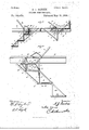
The invention consists, further,in certain novel details of construction, hereinafter more panying drawings, 'wherein- V Figure 1 is a perspective view of the end of a car the platform of which is provided with my improved steps, those on one side being in the lowered or operative position, while those on the other side are in the raised or horizontalposition. Fig. 2is a section of thesame. Fig. 3 is a side view to show the operating mechanism.
Referring by letter to the drawings, A designates the platform, having the openings B B at each end, in which the steps operate, it being my desire to bring the steps in both the lowered and raised positions within the line of the outside'of the car.
Grepresents a frame which depends from the, platform near the inner end of each opening B, and it comprisesthe vertical bars 0 cand the-horizontal bar 0, which connects the lower endsof the vertical bars. This frame is braced by fthinclined braces D D, which depend the length of the car, and F F representswing- 5 5 ing arms which are mounted at their upper ends on this rod. Similar arms,'G G, are pivoted at their upper ends to the sides of the openings BB at a distance from the upper. ends of the arms F Fequal to the width of a tread of the proposed steps. The arms G are about twice the length of the arms F, andtheir centers are connectedto the lower ends of the said arms Fby the links HH. 7 f
It will be evident that if the upper ends of the arms F and G are pivoted at the same level and the ends of the links H are com nected thereto at equal distances from their pivots the said links will be horizontal in'any position which the swinging arms may assume. The upper edges of the links are provided withhorizontal inward-extending'flanges h h, for a purpose hereinafter explained.
I I represent swinging arms, which are pivoted at one end to the vertical bars a 0 near their upper ends, and they are divided at their other ends to formthe forks K K. The arms k k, which comprise the said forks, are connected at their lower ends by the bars L, which have inward-extending flanges Z, for a purpose to be hereinafter explained.
The lower ends of the arms G G are provided with the outward-extending angle-arms M M, and the extremities of the latter are connected to intermediate points of the arms I I by means of the links N N, which have in= ward-extending flanges n n. It will now be. seen that when the arms F and G are in their vertical position the lower end of the arm G will bear against the horizontal bar 0', and the links Hwill be horizontal, the armsI I will be inclined at-an angle of about forty=five degrees, and the bars L at the lower ends of? the arms I will be horizontal, as also will be thelinks N N. When the arms F and Gare swung up to their horizontal position, the links H will still be horizontal. As before described, the link N is connected at the outer end to aninten mediate point of the arm I, and at a point near the inner end'to the extremity of the angle -too arm M, which is on the lower end of the arm G. The upper pivoted ends of the arms G and I are in the same vertical line; but the ends of the arms G are above those of the arms I, whereas the distance from the pivoted end of the arm G to the point where the link is pivoted thereto is about the same as the distance from the pivoted end of the arm Ito the point where the other end of the said link is pivoted thereto. Therefore, as the lower ends of the said arms are swung upward, the outer ends of the links N are drawn upward and inward by the arms I, and the inner ends of the said links are swung downward and outward by the arms G, thereby causing the links to turn over and assume a position the reverse of that previously occupied. WVhen thelinks N N are in the reversed position described, the arms I I are inclined upward at an angle of about forty-five degrees, and therefore the bars L L are vertical.
0 represents the top tread, which is secured to the horizontal flanges h on the links H.
P represents thesecond tread,which is simi lar to the tread O, and is secured to the flanges n on thelinks N; and Q represents the bottom tread, which is secured to the flanges Z on the bars L.
0 represents the top riser, which is secured at the ends to the swinging arms F F, and P represents a riser which is secured to the arms G G below the point where the ends of the links H are pivoted thereto. The rear edge of the tread 0 projects ashortdistancebeyond the ends of the links H, and therefore when the said links assume their horizontal position in the closed position of the step the rear edge of the said tread will exactly meet the front edge of the riser O, which is brought to the horizontal position by the armsF F, and their upper surfaces will be flush with each other and with the platform A. (See Fig. 1.) When the steps are folded, the links N are (as before described) turned over or reversed,'and therefore the tread P, which is secured thereto, will be similarly reversed and will fold over the riser P, so that its previous front edge will be brought in contact with the front edge of the tread 0. Thus the previous'under side of the tread P will be flush with the upper side of the tread O, and the riser P will be concealed under the tread P. The present outer (previous inner) edge of the tread P will fold up against the lower (previous inner) edge of the lowest tread, Q, and as the latteris in a vertical position it will form afoot-guard for theside of the platform. The arm F on one side of the steps (preferably the side toward the body of the car) is provided on the rear side with an angular bracket, F, comprising the converging barsff, which are connected together at their rear ends and are attachedat the opposite ends to the extremities of the arms F.
The arm G is provided on its rear side at the upper end with the angular bracket G,
and the bars g g, comprising the same, are connected at their rear ends, and are attached at their opposite ends to the arm G respectively at its upper end and at its central point. The bar g of the said bracket is extended beyond the arm G to form the handle B. It will be seen that the handle R and the bar 9 constitute a lever,which is pivoted at the same point as the upper end of the swinging arm G.
S represents a link,which is attached at its opposite ends to the apexes of the angular brackets G and F, respemely.
T represents a bracket which is secured to the platform A, and. it is provided with a notch, U, to receive and engage the handle when the latter is turned so as to close the steps. It will be seen that when the steps are raised or closed the handle'is drawn inward at the upper end, and it is preferably so arranged that when it comes in line with the notchU it willautomatically spring thereinto.
From the foregoing description it will be readily seen that by a mere swing of the bandle R the steps may be either opened (with the treads and risers in their proper relative positions to allow persons to enter the car)'or closed, (with the said treads and risers drawn up to form an extension of the platform, with a guard at its outer edge.) Thus the openings B B in the platform are closed, thereby enlarging the available space, and preventing persons from falling or being thrown from the platform while passing from one car to the next.
A gate may be hung to the corner of the car, to extend over the foot guard, and thus prevent all possibility of accident. By thus drawing up the steps persons are prevented from jumping on or off the platform while the cars are in motion.
It will be seen that if necessary the number of treads and risers in the steps may be increased, it being only necessary to'duplicate certain parts of the operating device, and also the number of treads may be reduced.
IIO
Having thus described my invention, I-
claim--- 1. In combination with the platform of a car, the folding steps connected thereto for si multaneous operation,whereby when the steps are folded they form a continuation or extension of the car-platform, substantially as speci- 2. The combination,with a platform, of the swinging arms pivoted thereto, the steps having the risers secured to the arms, and the treads pivoted to the arms and adapted to assume a horizontal position flush with the plat form when the arms are swung upward, substantially as specified.
3. The combination, with a car-platform having the openings B B at the sides, of the swinging arms F G, pivoted to the sides of the openings and having the risers secured thereto, the swinging arms I, having the bottom treads, Q, attached thereto, and the treads P and O, pivoted to and connecting the said arms, whereby when the steps are raised or sears-19 3 folding'stepsconnected together for simultane-.
ous operation, and adapted when folded to come on ahorizontal line with'the platform and form a continuation thereof, the lowest tread of the steps standing in a vertical posi-- tion at the end to form a guard, as set forth.
5. The combination," with a car-platform, of the arms F F, having the top riser attached thereto, the arms GG, having the second riser attached thereto, the top tread pivoted between the arms F and G,the arms I I, having thelowest tread attached thereto, and the' tread P, pivoted to the arms G and I,whereby all the arms move simultaneously and the treads and risers form an extension to the platform, substantially as specified.
6. The combination, with-a'platform, of the arms F F, the arms G G, pivoted on the same level as the arms F, the tread pivoted to the lower ends of the arms F and the intermediate points of the arms G, the arms I I, pivoted at their upper ends under the upper ends of'the arms G and having a tread attached rigidly thereto, and the tread P, pivoted to the lower ends of the arms G andint'ermediate points of the arms I, substantially as specified.
7. The combination, with a car-platform, of
the swinging arms F, G, and I, connected together and having the treads attached-thereto,
the handle attached to one of the arms, and means, substantially'as described, to lock the handle when the steps are raised, substantially as specified.
8.-The combination, with a car-platform, of the swinging arms I, the arms G, connected thereto and having a handle, R, the arms F,
connected to'the arms G by the links S, the treads attached to the said arms, and the bracket attached. to the car-platform and adapted to engage the said handle, substantially as specified.
9. The combination, with a carplatform, the swinging arms connected together and having the treads attached thereto, the handle attached to one of the arms, and the bracket T, having a notch, U, to receive and engage the said handle, substantially as and for the purpose specified.
10. The combination, with a carplatform, of
the swinging arms F and G, the arms I, having the forks K at their free ends, the tread Q, attached to the said forks, the treads P and 0, attached to the arms and connecting them 7 together for simultaneous operation, and .the I handle attached-to one of the arms, substantially as specified.
11. The combination,with a car-platform, of the arms F F, having the risers secured thereto, the arms G G, bent forward at their lower ends to form the arms M M, and having the riser P secured thereto, the arms I, having the forks K K at their lower ends, and the bars L, connectin the arms of the said forks, the tread secure to the bars L, the treads O and P, pivoted, respectively, between the arms F G and G I, and the handle attached to one ofthe arms, substantially as specified.
12. The combination, with a platform, of the arms F G I, the links N, pivoted to the arms G and I, the links H, pivoted to the arms F and G, and the treads attached to the said links, substantially as specified.
13. The combination,with a car-platform, of
the arms I I, having the barsL on theirlower ends provided with the flanges Z, the arms G,
connected to the arms I by the links N, having flanges n, the arms F, connected to the arms G by the links H, having the flanges h, and the treads O, P, andQ, secured to the flanges h, n, and Z, respectively, substantially as specified.
14. The combination, with a car-platform, of I the-arrn F, provided with a bracket, F','the arm G, provided with a bracket, G, the arm I,connected to the arm G, the treads attached to the said arms, the link S, connectingthe brackets F and G, and the operating-handle attached to the bracket G, substantially as specified.
15. The combination, with a ear platform and the depending frame 0, of-the folding steps adapted in the lowered position to bear against the depending frame and in the raised position to form an extension to the platform, substantially as specified. 7
In testimonythat I claim the foregoing-as my own I have hereto affixed mysignaturein-pres;
ence of two witnesses.
ARTHUR J. BARBER.
Witnesses:
O. J. WILLIAMS, D. GAYLORD.
Publications (1)
| Publication Number | Publication Date |
|---|---|
| US382679A true US382679A (en) | 1888-05-15 |
Family
ID=2451672
Family Applications (1)
| Application Number | Title | Priority Date | Filing Date |
|---|---|---|---|
| US382679D Expired - Lifetime US382679A (en) | barber |
Country Status (1)
| Country | Link |
|---|---|
| US (1) | US382679A (en) |
Cited By (1)
| Publication number | Priority date | Publication date | Assignee | Title |
|---|---|---|---|---|
| AU601567B2 (en) * | 1987-07-13 | 1990-09-13 | Conoco Inc. | Improved polymeric drag reducer performance by injection through a land-length die |
-
0
- US US382679D patent/US382679A/en not_active Expired - Lifetime
Cited By (1)
| Publication number | Priority date | Publication date | Assignee | Title |
|---|---|---|---|---|
| AU601567B2 (en) * | 1987-07-13 | 1990-09-13 | Conoco Inc. | Improved polymeric drag reducer performance by injection through a land-length die |
Similar Documents
| Publication | Publication Date | Title |
|---|---|---|
| US382679A (en) | barber | |
| US177526A (en) | Improvement in vehicle-seats | |
| US1180215A (en) | Automatically-operated folding step. | |
| US775366A (en) | Folding car-step. | |
| US997077A (en) | Street-car fender. | |
| US1129238A (en) | Extensible car-step. | |
| US213429A (en) | Improvement in carriage-steps | |
| US482744A (en) | Vestibule-car | |
| US302551A (en) | Mary elizabeth ferguson | |
| US160651A (en) | Improvement in shifting seats for carriages | |
| US616230A (en) | Extension car-step | |
| US581739A (en) | Laugh | |
| US539342A (en) | brown | |
| US903352A (en) | Folding step for vehicles. | |
| US672564A (en) | Railway-car. | |
| US1180340A (en) | Automobile-body. | |
| US953538A (en) | Extension car-step. | |
| US574310A (en) | James a | |
| US299437A (en) | Wagon jump-seat | |
| US1218006A (en) | Collapsible seat for vehicles. | |
| US704776A (en) | Car-fender. | |
| US813475A (en) | Car-fender. | |
| US1140641A (en) | Combined folding door-step and seat for cars. | |
| US462769A (en) | Combined car step and gate | |
| US945531A (en) | Car-step. |