US3818663A - Wall coping - Google Patents
Wall coping Download PDFInfo
- Publication number
- US3818663A US3818663A US00358342A US35834273A US3818663A US 3818663 A US3818663 A US 3818663A US 00358342 A US00358342 A US 00358342A US 35834273 A US35834273 A US 35834273A US 3818663 A US3818663 A US 3818663A
- Authority
- US
- United States
- Prior art keywords
- coping
- clip
- end portions
- wall
- flange
- Prior art date
- Legal status (The legal status is an assumption and is not a legal conclusion. Google has not performed a legal analysis and makes no representation as to the accuracy of the status listed.)
- Expired - Lifetime
Links
Images

Classifications
-
- E—FIXED CONSTRUCTIONS
- E04—BUILDING
- E04D—ROOF COVERINGS; SKY-LIGHTS; GUTTERS; ROOF-WORKING TOOLS
- E04D3/00—Roof covering by making use of flat or curved slabs or stiff sheets
- E04D3/40—Slabs or sheets locally modified for auxiliary purposes, e.g. for resting on walls, for serving as guttering; Elements for particular purposes, e.g. ridge elements, specially designed for use in conjunction with slabs or sheets
- E04D3/405—Wall copings
Definitions
- a coping for a wall comprises fixing clips spaced along May 9, 1972 Great Britain 21656/72 and secured to the top of wall and having a cambered surface extending acrossthe wall, and coping elements [52] US. Cl. 52/300, 52/60 which when free haye no camber or a lesser camber [51] Int. Cl. E04c 2/00 than the clips and which are held down on the clips by [58] Field of Search 52/300, 102, 58, 222, 169, slidable clips disposed at opposite sides of the wall.
- the coping elements are made from stiff but resilient sheet material so as to have a drainage camber im- [56] References Cited parted to them by being held down on the clips be- UNITED STATES PATENTS Andrews 52/300 neath but at the same time to be taut and rattle-free.
- This invention relates to copings.
- a coping comprising a fixing clip adapted to straddle the top of a wall, which clip includes a central portion which is cambered viewed in a direction along the coping and end portions which depend from the ends of the central portion, a coping element for straddling the top of the wall which coping element is made from stiff but resilient sheet material and has a central portion and end portions depending from the ends of the central portion the central and end portions of the coping element respectively overlapping the central and end portions of the fixing clip over at least part of the width of the clip, the central portion of the coping element having no camber or a lesser camber than the central portion of the clip, one of the end portions of the coping element being hingedly interengageable with one of the end portions of the fixing clip, and the other end portions of the coping element and the fixing clip having flanges which project towards the wall and which are disposed in alignment with each other in a direction lengthwise of the coping, the flange on the coping element for this purpose terminating short
- the flanges on said other end portions of the coping element and the fixing clip are inclined inwardly and upwardly.
- the said interengaging formations comprise a lip on the flange and a corresponding slot in the sliding clip to embrace the lip.
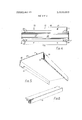
- FIG. 1 is an end view of a coping according to the present invention in position on a wall
- FIG. 2 is a perspective view from above of the fixing clip of the coping shown in FIG. 1,
- FIG. 3 is a sectional end elevation on the plane 3-3 of FIG. 2,
- FIG. 4 is a plan view of the fixing clip
- FIG. 5 is an underneath perspective view of the coping element
- FIG. 6 is a perspective view of a sliding clip.
- a coping made up from fixing clips 10, coping elements 11 and sliding clips 12.
- the fixing clips are fastened by screws 13 to the top of a wall, which is shown in the drawings as an I I inch cavity wall, and the coping elements are subsequently secured to the fixing clips by the sliding clips, each coping element being secured to fixing clips at each of its ends, and each fixing clip (except the endmost clip) serving to retain the ends of two coping elements.
- each fixing clip is made in three parts which are secured together.
- the three parts comprise a central body part 15 which is of wide and shallow top-hat section and which is slightly curved along its length, and two end parts 16, 17 which provide vertical end portions 18, 19 and inwardly and upwardly inclined flanges 20 terminating in lips 21.
- Each of the end parts has the same width as the channel on the underside of the central part 15 and has an attachment tongue which projects into this channel and which is secured to the part 15 by rivets 22.
- a rubber sealing strip 23 having parallel sealing ribs 24 extends from the bottom end of the vertical portion 18 of end part 16, along the upper surface of the central part 15 to the bottom end of the vertical portion 19 of the other end part 17, and is secured in place by an adhesive.
- Countersunk holes 25 for the screws 13 are provided in the side flanges 26 of the central part.
- the vertical portion 18 is shorter than the vertical portion 19.
- the coping element 1 l is made from sheet metal has a flat central portion 28 and vertical end portions 29, 30 terminating in flanges 31, 32 and is proportioned so that when the element is correctly secured to the fixing clip, the central portion 28 being pressed on to the sealing strip of the fixing clip, the end portions 29, 30 lie against the sealing strip on the outer faces of parts l6, 17, the flange 32 of the coping element is disposed against the downwardly facing side of flange 20 on the end portion 17 of the fixing clip, and the flange 32 of the coping element is aligned with the other flange 20 of the fixing clip.
- Part of the length of flange 32 of the coping element equal to slightly more than half the width of the end part 18 of the fixing clip is cut away at each end of the coping element as indicated in FIG. 5.
- FIG. 6 shows a sliding clip 12 which is made from extruded aluminium and is designed to extend about the flange 20 and lip 21.
- the clip has one corner slightly bent upwards to enable the clip to be hammered along if necessary.
- fixing clips are first secured to the top of the wall by screws 13 and are disposed at pitch spacings equal to the length of the coping element.
- Each fixing clip except the endmost clips holds the abutting ends of two coping elements.
- Each coping element is attached to fixing clips at its ends by first hooking the flange 31 of the element under the flanges 20 of the end parts 17 of the clip and then rotating the element downwards about its flange 31 to place its central portion 28 on the central portions of the fixing clips and to bring the flange 32 into alignment with the flange 20 of the other end parts 18 of the clip, these flanges 20 being disposed where the flange 32 of the element is cut away.
- a sliding clip 12 is then engaged on the flange 32 and is pushed along the flange to bring it into engagement with the flange 20 and lip 21 of clip end part 16 and with the flange 32 of the next adjacent element, so that each sliding clip co-operates with one fixing clip to retain the abutting ends of two elements in place.
- the engagement between the sliding clip and the lip 21 prevents the sliding clip from disengaging from the flanges by moving transversely of itself towards the wall.
- the position of the endmost fixing clips is adjusted so that the whole of each of these clips is disposed under the associated coping element.
- the length of one cutaway part of flange 32 is of course appropriately increased;
- the screws 13 in one of the two sections of the wall may be used to secure joggled clips which extend over the side flange 26 of the central part of the clip so as to clamp the clip to the wall section but to permit the clip to slide relative to the wall section as the clip expands and contracts.
- the clips and coping elements may conveniently be made from aluminium alloy.
- the top of the wall will normally be inclined and the end part 17 with the longer end portion will be disposed at the higher edge of the wall.
- the pressure which is applied to the central portion 28 of the coping element when the flange 32 is held down by the sliding clip causes the central portion of the element, which is initially flat, to have substantially the same hogging curvature or camber as the central part of the fixing clip and results in substantial sealing pressure and an effective seal between the element and the sealing strip because the sealing pressure is distributed along the length of the central part.
- the sealing pressure could be increased further by imparting an initial negative or sagging camber to the central portion of the coping element, but this has not been found necessary.
- the fixing clips are of stiff construction so that overtightening of the screws 13 cannot pull the central part down sufficiently to remove the curvature.
- the coping elements may be formed in substantial lengths, eg 3 metre lengths and in this case an extra fixing clip may be provided under each coping element at its mid-length, the flanges 31 and 32 being cut away for this purpose at the appropriate part of the element.
- a coping comprising a fixing clip adapted to straddle the top of a wall, which clip includes a central portion which is cambered viewed in a direction along the coping and end portions which depend from the ends of the central portion, a coping element for straddling the top of the wall which coping element is made from stiff but resilient sheet material and has a central portion and end portions depending from the ends of the central portion, the central and end portions of the coping element respectively overlapping the central and end portions of the fixing clip over at least part of the width of the clip, the central portion of the coping element having no camber or a lesser camber than the central portion of the clip, one of the end portions of the coping element being hingedly interengageable with one of the end portions of the fixing clip, and the other end portions of the coping element and the fixing clip having flanges which project towards the wall and which are disposed in alignment with each other in a direction lengthwise of the coping, the flange on the coping element for this purpose terminating short of the end of the element
- a coping as claimed in claim 1 wherein the flanges on said other end portions of the coping element and the fixing clip are inclined inwardly and upwardly.
- a coping as claimed in claim I, wherein the said interengaging formations comprise a lip on the flange and a corresponding slot in the sliding clip to embrace the lip.
Landscapes
- Life Sciences & Earth Sciences (AREA)
- Sustainable Development (AREA)
- Engineering & Computer Science (AREA)
- Architecture (AREA)
- Civil Engineering (AREA)
- Structural Engineering (AREA)
- Clamps And Clips (AREA)
- Seal Device For Vehicle (AREA)
Applications Claiming Priority (1)
| Application Number | Priority Date | Filing Date | Title |
|---|---|---|---|
| GB2165672A GB1392369A (en) | 1972-05-09 | 1972-05-09 | Copings |
Publications (1)
| Publication Number | Publication Date |
|---|---|
| US3818663A true US3818663A (en) | 1974-06-25 |
Family
ID=10166602
Family Applications (1)
| Application Number | Title | Priority Date | Filing Date |
|---|---|---|---|
| US00358342A Expired - Lifetime US3818663A (en) | 1972-05-09 | 1973-05-08 | Wall coping |
Country Status (8)
| Country | Link |
|---|---|
| US (1) | US3818663A (it) |
| BE (1) | BE799329A (it) |
| CA (1) | CA977122A (it) |
| DE (1) | DE2323274A1 (it) |
| FR (1) | FR2184034B1 (it) |
| GB (1) | GB1392369A (it) |
| IT (1) | IT987232B (it) |
| NL (1) | NL7306477A (it) |
Cited By (11)
| Publication number | Priority date | Publication date | Assignee | Title |
|---|---|---|---|---|
| JPS5279516A (en) * | 1975-12-26 | 1977-07-04 | Abc Trading Co | Readyymade top beam of beam |
| JPS53123208U (it) * | 1977-03-09 | 1978-09-30 | ||
| WO1982000314A1 (en) * | 1980-07-23 | 1982-02-04 | Cooper C | Roof ridge capping system |
| JPS57155469A (en) * | 1981-03-19 | 1982-09-25 | Yamaide Kousan Kk | Water-proofing of land roof parapet and cap beam thereof |
| FR2546949A1 (fr) * | 1983-06-02 | 1984-12-07 | Profilor | Dispositif pour recouvrir de facon etanche le sommet d'un mur et notamment d'un mur d'acrotere |
| US4753420A (en) * | 1987-07-06 | 1988-06-28 | Kaaria Ray T | Railing system |
| US5704176A (en) * | 1994-08-19 | 1998-01-06 | Crown Partnership | Snap-on coping holddown |
| US5893247A (en) * | 1998-01-13 | 1999-04-13 | W. P. Hickman Company | Coping |
| US20030095546A1 (en) * | 2001-11-20 | 2003-05-22 | Tsuneyuki Sakano | IP telephone terminal searching for a destination with a telephone number to set up a call connection over an IP network |
| US20050028464A1 (en) * | 2001-09-14 | 2005-02-10 | Metal-Era, Inc. | Coping assembly having a stone and mortar appearance |
| CN114000659A (zh) * | 2021-10-13 | 2022-02-01 | 谭涵 | 一种防火保温岩棉复合板 |
Families Citing this family (3)
| Publication number | Priority date | Publication date | Assignee | Title |
|---|---|---|---|---|
| GB9109309D0 (en) * | 1991-04-30 | 1991-06-19 | Alumasc Ltd | Gutter systems |
| FR3010426B1 (fr) * | 2013-09-12 | 2016-02-12 | Dal System Ind | Crochet de couvertine |
| GB2566033B (en) * | 2017-08-30 | 2021-06-02 | Western Expanded Metal Industries Company Ltd | Coping brackets and methods of manufacturing coping brackets |
Citations (4)
| Publication number | Priority date | Publication date | Assignee | Title |
|---|---|---|---|---|
| US2281092A (en) * | 1940-04-26 | 1942-04-28 | Revere Copper & Brass Inc | Coping cap |
| US2554779A (en) * | 1949-08-05 | 1951-05-29 | Overly Mfg Company | Coping |
| CA553477A (en) * | 1958-02-25 | Aluminum Company Of America | Coping structures | |
| GB1180965A (en) * | 1967-06-12 | 1970-02-11 | P J P Trading Ltd | An Improved Coping for External Walls. |
-
1972
- 1972-05-09 GB GB2165672A patent/GB1392369A/en not_active Expired
-
1973
- 1973-05-08 CA CA170,651A patent/CA977122A/en not_active Expired
- 1973-05-08 US US00358342A patent/US3818663A/en not_active Expired - Lifetime
- 1973-05-09 DE DE2323274A patent/DE2323274A1/de active Pending
- 1973-05-09 BE BE130943A patent/BE799329A/xx unknown
- 1973-05-09 IT IT23881/73A patent/IT987232B/it active
- 1973-05-09 FR FR7316794A patent/FR2184034B1/fr not_active Expired
- 1973-05-09 NL NL7306477A patent/NL7306477A/xx not_active Application Discontinuation
Patent Citations (4)
| Publication number | Priority date | Publication date | Assignee | Title |
|---|---|---|---|---|
| CA553477A (en) * | 1958-02-25 | Aluminum Company Of America | Coping structures | |
| US2281092A (en) * | 1940-04-26 | 1942-04-28 | Revere Copper & Brass Inc | Coping cap |
| US2554779A (en) * | 1949-08-05 | 1951-05-29 | Overly Mfg Company | Coping |
| GB1180965A (en) * | 1967-06-12 | 1970-02-11 | P J P Trading Ltd | An Improved Coping for External Walls. |
Cited By (14)
| Publication number | Priority date | Publication date | Assignee | Title |
|---|---|---|---|---|
| JPS5279516A (en) * | 1975-12-26 | 1977-07-04 | Abc Trading Co | Readyymade top beam of beam |
| JPS577711Y2 (it) * | 1977-03-09 | 1982-02-15 | ||
| JPS53123208U (it) * | 1977-03-09 | 1978-09-30 | ||
| US4532739A (en) * | 1980-07-23 | 1985-08-06 | Marley Tile A.G. | Roof ridge capping system |
| WO1982000314A1 (en) * | 1980-07-23 | 1982-02-04 | Cooper C | Roof ridge capping system |
| JPS57155469A (en) * | 1981-03-19 | 1982-09-25 | Yamaide Kousan Kk | Water-proofing of land roof parapet and cap beam thereof |
| FR2546949A1 (fr) * | 1983-06-02 | 1984-12-07 | Profilor | Dispositif pour recouvrir de facon etanche le sommet d'un mur et notamment d'un mur d'acrotere |
| US4753420A (en) * | 1987-07-06 | 1988-06-28 | Kaaria Ray T | Railing system |
| US5704176A (en) * | 1994-08-19 | 1998-01-06 | Crown Partnership | Snap-on coping holddown |
| US5893247A (en) * | 1998-01-13 | 1999-04-13 | W. P. Hickman Company | Coping |
| US20050028464A1 (en) * | 2001-09-14 | 2005-02-10 | Metal-Era, Inc. | Coping assembly having a stone and mortar appearance |
| US20030095546A1 (en) * | 2001-11-20 | 2003-05-22 | Tsuneyuki Sakano | IP telephone terminal searching for a destination with a telephone number to set up a call connection over an IP network |
| US7480257B2 (en) * | 2001-11-20 | 2009-01-20 | Oki Electric Industry Co., Ltd. | IP telephone terminal searching for a destination with a telephone number to set up a call connection over an IP network |
| CN114000659A (zh) * | 2021-10-13 | 2022-02-01 | 谭涵 | 一种防火保温岩棉复合板 |
Also Published As
| Publication number | Publication date |
|---|---|
| NL7306477A (it) | 1973-11-13 |
| BE799329A (fr) | 1973-08-31 |
| IT987232B (it) | 1975-02-20 |
| CA977122A (en) | 1975-11-04 |
| FR2184034B1 (it) | 1980-06-13 |
| GB1392369A (en) | 1975-04-30 |
| FR2184034A1 (it) | 1973-12-21 |
| DE2323274A1 (de) | 1973-11-29 |
Similar Documents
| Publication | Publication Date | Title |
|---|---|---|
| US3818663A (en) | Wall coping | |
| US3438168A (en) | Building outer wall structure | |
| US3662509A (en) | Insulated roof structure | |
| US3696575A (en) | Expansion joint cover | |
| US3469873A (en) | Joint with planar connector member | |
| US4135342A (en) | Insulated metal roofing and siding system | |
| US3058265A (en) | Roofing shingle and shingle assembly | |
| US4184299A (en) | Roof construction | |
| US3336705A (en) | Flush panel stringer assembly | |
| US3643388A (en) | Flexible expansion joint for structures | |
| US4648218A (en) | Interlocking roof edge fascia system | |
| US5031367A (en) | Roof edge fascia system | |
| US4638532A (en) | Mechanical fastening system | |
| US3238687A (en) | Panel | |
| US2857995A (en) | Wall facing | |
| US4170810A (en) | Fastening devices for flexible sheets | |
| EP0056021A1 (en) | FIRST COVER FOR A SLOPED ROOF. | |
| US3323269A (en) | Roofing and siding panel construction with securing means for accommodating differential expansion | |
| GB2095304A (en) | Standing seam roof system | |
| US3967423A (en) | Skylight system | |
| US4099356A (en) | Seamed rib panel assembly | |
| US3425172A (en) | Roof expansion joint cover and flashing | |
| US3603056A (en) | Batten seam joint | |
| US2702514A (en) | Counterflashing | |
| USRE26056E (en) | Combination water dam and gravel stop |