US3816830A - Cylindrical array antenna - Google Patents
Cylindrical array antenna Download PDFInfo
- Publication number
- US3816830A US3816830A US00093195A US9319570A US3816830A US 3816830 A US3816830 A US 3816830A US 00093195 A US00093195 A US 00093195A US 9319570 A US9319570 A US 9319570A US 3816830 A US3816830 A US 3816830A
- Authority
- US
- United States
- Prior art keywords
- elements
- intermediate signals
- group
- phase
- radiating
- Prior art date
- Legal status (The legal status is an assumption and is not a legal conclusion. Google has not performed a legal analysis and makes no representation as to the accuracy of the status listed.)
- Expired - Lifetime
Links
- 238000009826 distribution Methods 0.000 claims abstract description 49
- 239000011159 matrix material Substances 0.000 claims abstract description 26
- 230000005855 radiation Effects 0.000 claims abstract description 12
- 238000005286 illumination Methods 0.000 claims description 28
- 230000008878 coupling Effects 0.000 claims description 18
- 238000010168 coupling process Methods 0.000 claims description 18
- 238000005859 coupling reaction Methods 0.000 claims description 18
- 230000010363 phase shift Effects 0.000 claims description 12
- 230000005540 biological transmission Effects 0.000 claims description 7
- 239000007787 solid Substances 0.000 claims description 2
- 230000005284 excitation Effects 0.000 description 21
- 238000000034 method Methods 0.000 description 8
- 238000012546 transfer Methods 0.000 description 6
- 230000008859 change Effects 0.000 description 4
- 238000003491 array Methods 0.000 description 3
- 230000008901 benefit Effects 0.000 description 2
- 238000012986 modification Methods 0.000 description 2
- 230000004048 modification Effects 0.000 description 2
- 241000283986 Lepus Species 0.000 description 1
- 238000013459 approach Methods 0.000 description 1
- 230000001934 delay Effects 0.000 description 1
- 238000013461 design Methods 0.000 description 1
- 238000010586 diagram Methods 0.000 description 1
- 230000000694 effects Effects 0.000 description 1
- 238000004321 preservation Methods 0.000 description 1
- 230000000750 progressive effect Effects 0.000 description 1
- 230000004044 response Effects 0.000 description 1
Images
Classifications
-
- H—ELECTRICITY
- H01—ELECTRIC ELEMENTS
- H01Q—ANTENNAS, i.e. RADIO AERIALS
- H01Q3/00—Arrangements for changing or varying the orientation or the shape of the directional pattern of the waves radiated from an antenna or antenna system
- H01Q3/24—Arrangements for changing or varying the orientation or the shape of the directional pattern of the waves radiated from an antenna or antenna system varying the orientation by switching energy from one active radiating element to another, e.g. for beam switching
- H01Q3/242—Circumferential scanning
-
- D—TEXTILES; PAPER
- D06—TREATMENT OF TEXTILES OR THE LIKE; LAUNDERING; FLEXIBLE MATERIALS NOT OTHERWISE PROVIDED FOR
- D06M—TREATMENT, NOT PROVIDED FOR ELSEWHERE IN CLASS D06, OF FIBRES, THREADS, YARNS, FABRICS, FEATHERS OR FIBROUS GOODS MADE FROM SUCH MATERIALS
- D06M15/00—Treating fibres, threads, yarns, fabrics, or fibrous goods made from such materials, with macromolecular compounds; Such treatment combined with mechanical treatment
- D06M15/19—Treating fibres, threads, yarns, fabrics, or fibrous goods made from such materials, with macromolecular compounds; Such treatment combined with mechanical treatment with synthetic macromolecular compounds
- D06M15/21—Macromolecular compounds obtained by reactions only involving carbon-to-carbon unsaturated bonds
- D06M15/31—Macromolecular compounds obtained by reactions only involving carbon-to-carbon unsaturated bonds of unsaturated nitriles
-
- H—ELECTRICITY
- H01—ELECTRIC ELEMENTS
- H01Q—ANTENNAS, i.e. RADIO AERIALS
- H01Q3/00—Arrangements for changing or varying the orientation or the shape of the directional pattern of the waves radiated from an antenna or antenna system
Definitions
- ABSTRACT Disclosed is a cylindrical array antenna capable of radiating a beam which may be steered in coarse and fine increments to selectable beam positions.
- such an array comprises a plurality of radiating elements arranged in a circular configuration, a plurality of phase shifters which develops a group of intermediate signals having a selected phase distribution and suitable for radiation from the array and a switching matrix which accepts the group of intermediate signals and supplies them to a selected group of the radiating elements.
- the switching matrix and the phase shifters are electronically controlled so as to cause the beam to be steered to different positions, steering in coarse increments being accomplished by selecting different groups of elements and steering in fine increments being accomplished by selecting different phase distributions for the intermediate signals.
- This invention relates to array antennas and more specifically to an electronically steered array capable of radiating a beam which may be steered in coarse and fine increments to selectable beam positions.
- Antennas capable of radiating such a beam are useful in many sitnations especially in surveillance and IFF applications where the beamis to be scanned in angular sectors or over a full 360. In such a case a technique is required to scan the antenna beam, (usually a broad fan beam in elevation) in continuous or at least fine increments in azimuth in a manner which does not introduce beam distortion.
- Electronically scanned antennas overcome the slow speed and beam agility problems of the mechanical antennas but heretofore have proved to be poor analogs of the mechanical antennas in various other respects.
- Applicant overcomes the problems inherent in both of these techniques bypreserving the order of illumination of the elements (a phrase which is more clearly described hereinafter) when switching between groupsof elements thereby leaving his phase shifters for the purpose of beam steering in fine increments a feature heretofore unknown to the art.
- an array antenna capable of radiating a beam which may be steered to selectable beam positions.
- the antenna includes an aperture comprising a plurality of radiating elements arranged along the perimeter of a predetermined path having a curvature. Also included are means, responsive to a supplied input signal, for developing a predetermined number of intermediate signals suitable for radiation from the elements and having a selected phase distribution.
- the antenna further includes means for selecting a group of radiating elements from which the intermediate signals are to be radiated.
- each of the intermediate signals to a different element in the selected group of radiating elements in an independently selectable positional order of illumination on the aperture to cause a beam to be radiated from the group in a direction which is determined by the location of the group along the perimeter and by the phase distribution of the intermediate signals.
- the antenna includes means for controlling the selection of the group of elements and the selection of the positional order of illumination, thereby providing the ability to steer the beam to different beam positions.
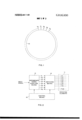
- FIG. 1 is an illustration of a plurality of radiating elements arranged in a circular configuration and useful in an array antenna built in accordance with the invention
- FIG. 2 is a-block diagram illustrating an embodiment of the invention
- FIGS. 3 and 3A are a blockand schematic illustration showing one possible interconnection of the intermediate signal supplying means, the switching matrix, and the radiating elements for use in the embodiment of FIG. 2, and
- FIG. 4 is a block illustration of one possible control means useful in the embodiment of FIG. 2..
- FIG. 1 there is shown a plurality of radiating elements a through a, arranged along the perimeter of a predetermined path, shown by circle 10, at a convenient inter-element spacing (for' example onehalf wavelength).
- a convenient inter-element spacing for' example onehalf wavelength.
- any suitable type of radiating elements such as dipoles, may be used for the elements a through a,,, de-
- an appropriate number of elements can be omitted from thearray of FIG. 1 along the corresponding section of the circle.
- Many other modifications of theelements and their particular'arrangement to produce radiated beams having specific characteristics will be obvious to those skilled in the art.
- the current path along which the elements lie need not be perfectly circular (or cylindrical in the case where there are layers of elements) but may be shaped to fit the fuselage of an aircraft. It will also be recognized by those skilled in the a'rtthat when different types of radiating elements or additional layers of elements similar to those of FIG. 1 are placed one above another the fan portion of the beam can be sufficiently narrowed to create a pencil-type beam.
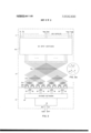
- FIG. 2 there is shown in block form an embodiment of the invention that includes an array 11 of 128 radiating elements (labeled a through a which may be arranged in a cylindrical configuration as in FIG. 1.
- an input electrical signal (either pulse or cw) which may be derived in a transmitter or any other suitable signal generator commonly used for this purpose in connection with conventional array antennas.
- Block 13 comprises means, responsive to the supplied input signal, for developing a predetermined number of intermediate signals suitable for radiation from the elements in array 11 and having a selected phase distribution. These-intermediate signals cooperate to form a complete aperture excitation which can be coupled to a selected group of the radiating elements (the radiating aperture) in array 11 to cause a beam to be radiated therefrom.
- the number of intermediate'signals developed in this case eight, supplied on lines b through b will determine the number of radiating elements in the selected group (eight) and therefore, the width of the resulting radiated beam, since the coupling means hereinafter described couples each intermediate signal to a different element in the selected group.
- the signal on line b may be coupled to element a, and likewise for b and a, etc. This establishes a positional order of illumination for the elements within the group.
- the aperture excitation formed by the intermediate signals cause a beam to be radiated from the selected elements and the direction of this beam can be varied'by varying the phase distribution i.e., the progressive phase shift between individual intermediate signals of the intermediate signals.
- this aperture excitation is coupled to the previously mentioned se lected group of radiating elements (a, through a in a particular order of illumination, (b to a b to a etc.) then, as is well known in the art, a linear variation of this phase distribution (in fine increments) has the effect of varying the direction of the beam radiated from the group of elements in very fine increments, thus achieving a practical equivalency to the continuous scanning ability of a mechanically rotating antenna which scans the area covered by the radiating aperture.
- the switching matrix 14 of FIG. 2 comprises means for selecting a group of elements from which the intermediate signals are to be radiated and means for coupling, in a predetermined order of illumination, each of the intermediate signals to a different element in the selected group of the radiating elements.
- Matrix 14 is capable of coupling the aperture excitation formed by the eight intermediate signals to any selected group of elements within array 11.
- the minimum coarse steering increment is determined by the interelement spacing, since the minimum possible change in selecting a new group is to change a single radiating element. For example, if the first selected group included element's a through a then to advance the beam one coarse steering increment the second group would include elements a through a and so on.
- any group may be selected (i.e. the second or subsequently selected group may include elements a through a;,-,) discontinuous coarse steering is possible, giving arrays constructed in accordance with the invention significant beam steering agility.
- Block 15 represents means for controlling the selection of the group of elements and the selection of the phase distribution while preserving the predetermined order of illumination within each selected group.
- the beam from array 11 can be steered to different beam positions, with the steering in coarse increments being accomplished by controlling switching matrix 14 so as to select different groups of elements and steering in fine increments being accomplished by controlling unit 13 so as to select different phase distribution for the intermediate signals.
- Means 15 may be a suitably programmed digital computer, or a special purpose computer or other logic circuitry specially adapted to control units 13 and 14 so as to cause the beam to be steered in continuous or discontinuous increments.
- control means Since there are innumerable special purposes for arrays of this type in which the requirements for beam scanning will usually be different, a suitable control means will have to be selected in each case to suit the steering criteria for each array built in accordance with the invention.
- the order of illumination is preserved by control means 15.
- the intermediate signal appearing on line 11 is coupled to element 0 line [2 to element a and so on
- in the next selected group such as a through a line b would be coupled to the same corresponding element in this group, namely element a and line b to element 11 and so on.
- This preservation of the order of illumination allows either a uniform or non-uniform aperture excitation to be supplied to matrix 14 since as will be recognized by those skilled in the art, the amplitude distribution of the aperture excitation is likewise preserved when switching to different groups of elements, thus overcoming a major difficulty in the prior art.
- FIG. 2 Another advantage of the above array is that since a complete aperture excitation is generated by means 13, with means 14 only coupling this excitation to different groups of elements, necessary compensation for the curvatureof the array can be achieved simply and inexpensively unlike the various prior art systems.
- One method of compensating for the curvature of the array is illustrated in FIG. 2, where lines b through b used to supply the intermediate signals to the switching matrix 14, can be transmission lines of differing lengths whose delays are chosen to compensate for the curvature of the cylinder.
- FIG. 3 shows in block and schematic form specific embodiments of intermediate signal supplying means 13 and switching matrix 14.
- Unit 13 is shown as consisting of an input hybrid junction 16 having two outputs which are connected to a power divider network 18.
- the divider network 18 is in turn connected to 32 electronically controlled phase shifters 19 (although only 8 such phase shifters are shown for clarity) resulting in 32 individual output lines from unit 13.
- a suitable input signal may be fed to the sum port 20 of hybrid 16 to obtain a low side lobe sum pattern from the array by illuminating an entire 32 element radiating aperture of the array 11 in phase.
- a difference pattern may be obtained by feeding the input signal to the difference port 21 of hybrid 16, thereby illuminating one-half of the radiating aperture, in this case 16 radiating elements 180 out of phase with the other half.
- Divider network 18 may be of conventional design which provides a symmetrical in-p'hase tapered amplitude distribution for the 32 signals fed to the phase shifters (when radiating sum patterns). Within this divider network there may be introduced fixed transmission line lengths (similar to lines 1;, through 12 to provide an alternate method for compensating for the curvature of the array, therefore leaving the phase shifters 19 for the purpose of beam steering. Phase shifters 19 introduce a phase shift into each intermediate signal, to create a selected phase distribution across the 32 intermediate signals which determines the direction of the beam radiated from a selected group of 32 elements, thus achieving the requisite fine steering.
- each phase shifter 19 is controlled by control means 15 to provide a series of selectable linear phase distributions which in this case by way of example is assumed to be eight.
- Each individual phase shifter is conveniently chosen as a digital 4 bit 1 input lines control the phase shift of each phase shifter) diode phase shifter giving a 360 total phase shift in 22.5 increments, thus each individual phase shifter can provide 16 different phase shifts, however, when combined with the other phase shifters in the system there is provided a group of intermediate signals with 8 possible different phase distributions.
- Coupling means 14 is shown as a switching matrix consisting of transfer switches 21,, 21 and a bank of 32 SP4T (single pole four throw) switches 22. Shown in FIG. 3a are alternate states for the transfer switches which may be individually selected by the control means 15 to supply a particular intermediate signal to a particular SP4T switch in bank 22 thereby selecting the positional order of illumination by which the intermediate signals are coupled to the selected radiating elements independent of the selection of the radiating elements.
- the 32 SP4T switches 22 comprise means for selecting a group of elements from which the intermediate signals are to be radiated. A simple connection of the SP4T switches 22 then permits the 32 outputs of the transfer switches to be connected to a group of 32 radiating elements designated by the control means 15.
- the switching matrix couples the intermediate signals to the elements in array 11 by equal length paths thus ensuring that the aperture excitation created by means 13 will not be distorted in the matrix.
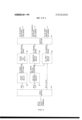
- the switching matrix in response to control means 15 may for example couple the 32 intermediate signals to any 32 consecutive elements of the 128 radiating elements in array ill in the aforementioned order of illumination. Therefore, there are 128 different coarse beam positions available 2.8 apart. Additionally, for each coarse beam position effected by matrix M there are eight fine beam positions effected by unit 13 by varying Turning now to FIG. 4 there is shown one embodiment of control means specially suited for operation with the array system of FIG. 3. In this embodiment a predetermined command signal is used to control the state of the switches in matrix 14 and the phase shifters in means 13.
- bits 1-3 will provide the information necessary to determine which of eight possible phase distributions are to be selected, with control for the individual phase shifters being provided by logic circuitry 24, 25, 26 and 31 in a manner which will be recognized by those skilled in the art.
- the next five larger bits (4-8) will provide the information necessary to determine the settings of the 80 transfer switches and in combination with bits 9 and 10, the settings of the 32 SP4T switches through logic circuitry 24, 27, 28, 29 and 31. Bits 4-10 therefore provide information to select between 128 beam positions.
- An array antenna capable of radiating a beam which may be steered in coarse and fine increments to selectable beam positions, comprising:
- an aperture comprising a plurality of radiating elements arranged along the perimeter of a predetermined path having a curvature
- each of said intermediate signals to a different element in said selected group of radiating elements in an independently selectable positional' order of illumination on said aperture to cause a beam to be radiated from said group in a direction which is determined by the location of said group along said perimeter and by the phase distribution selected for said intermediate signals;
- said coupling means comprises a plurality of electronically controlled switches arranged in a switching matrix.
- a cylindrical array antenna capable of radiating a beam which may be steered in coarse and fine increments to selectable beam positions, comprising:
- An aperture comprising a plurality of radiating elements arranged along the perimeter of an approximately cylindrical path having a curvature
- means including a plurality of electronically controlled switches, for selecting a number of said radiating elements equal to the number of said intermediate signals and from which said intermediate signals are to be radiated;
- each of said intermediate signals to a different element in said selected group of radiating elements in an independently selectable positional order of illumination on said aperture to cause a beam to be radiated from said group in a direction which is determined by the location of said group along said perimeter and by the phase distribution selected for said intermediate signals;
- control means comprises logic circuit means, responsive to a predetermined supplied beam position command signal, for controlling the state of said switches and the phase shift caused by each phase shifter to control the selection of said group of elements and the selection of said phase distribution so as to steer said beam to the beam position specified in said command signal.
- said intermediate signal supplying means further comprises a plurality of transmission line lengths each for adjusting the phase of one of said intermediate signals by a fixed amount to compensate for the curvature of said cylindrical path.
- said radiating elements include a plurality of layers of such elements each arranged in a circular configuration.
- a cylindrical array antenna capable of radiating a beam which may be steered in coarse and fine increments to selectable beam positions, comprising;
- an aperture comprising a plurality of radiating elements uniformly spaced along the perimeter of a circle and including at least one layer of such elements arranged to achieve 360 azimuth coverage from the array;
- means responsive to a supplied input signal and including a power divider network and a predetermined number of electronically controlled phase shifters fed by said power divider network, for developing a corresponding predetermined number of intermediate electrical signals suitable for radiation from said elements and having a selected phase distribution;
- means including a plurality of electronically controlled switches, for selecting a number of said radiating elements equal to the number of said intermediate signals and from which said intermediate signals are to be radiated;
- an electronically controlled solid state switching matrix for coupling, in an independently selectable positional order of illumination on said aperture, each of said adjusted intermediate signals to a different element in said selected group of radiating elements, to cause a beam to be radiated from said group in a direction which is determined by the location of said group along said perimeter and by the phase distribution of said intermediate signals;
- an aperture comprising a plurality of radiating elements arranged along the perimeter of a predetermined cylindrical path having a curvature
- each of said intermediate signals to a different element in said selected group of radiating elements in an independently selectable positional order of illumination on said aperture to cause a beam to be radiated from said group in a direction which is determined by the location of said group along said perimeter and by the phase distribution of said intermediate signals;
- said plurality of radiating elements includes at least one layer of such elements arranged in a cylindrical configuration to achieve 360 azimuth coverage from the array.
- said coupling means comprises a plurality of electronically controlled switches arranged in a switching matrix.
Landscapes
- Chemical & Material Sciences (AREA)
- Chemical Kinetics & Catalysis (AREA)
- Engineering & Computer Science (AREA)
- Textile Engineering (AREA)
- Variable-Direction Aerials And Aerial Arrays (AREA)
Priority Applications (5)
| Application Number | Priority Date | Filing Date | Title |
|---|---|---|---|
| US00093195A US3816830A (en) | 1970-11-27 | 1970-11-27 | Cylindrical array antenna |
| CA116908A CA931643A (en) | 1970-11-27 | 1971-06-29 | Cylindrical array antenna |
| GB3055271A GB1323384A (en) | 1970-11-27 | 1971-06-30 | Cylindrical array antenna |
| DE19712158416 DE2158416A1 (de) | 1970-11-27 | 1971-11-25 | Antennenanordnung |
| FR7142404A FR2115420B1 (enExample) | 1970-11-27 | 1971-11-26 |
Applications Claiming Priority (1)
| Application Number | Priority Date | Filing Date | Title |
|---|---|---|---|
| US00093195A US3816830A (en) | 1970-11-27 | 1970-11-27 | Cylindrical array antenna |
Publications (1)
| Publication Number | Publication Date |
|---|---|
| US3816830A true US3816830A (en) | 1974-06-11 |
Family
ID=22237678
Family Applications (1)
| Application Number | Title | Priority Date | Filing Date |
|---|---|---|---|
| US00093195A Expired - Lifetime US3816830A (en) | 1970-11-27 | 1970-11-27 | Cylindrical array antenna |
Country Status (5)
| Country | Link |
|---|---|
| US (1) | US3816830A (enExample) |
| CA (1) | CA931643A (enExample) |
| DE (1) | DE2158416A1 (enExample) |
| FR (1) | FR2115420B1 (enExample) |
| GB (1) | GB1323384A (enExample) |
Cited By (23)
| Publication number | Priority date | Publication date | Assignee | Title |
|---|---|---|---|---|
| US3964066A (en) * | 1975-01-02 | 1976-06-15 | International Telephone And Telegraph Corporation | Electronic scanned cylindrical-array antenna using network approach for reduced system complexity |
| EP0028969A1 (en) * | 1979-11-01 | 1981-05-20 | The Bendix Corporation | Omnidirectional side lobe sum and difference beam forming network for a multielement antenna array and method for determining the weights thereof |
| WO1986000760A1 (en) * | 1984-07-09 | 1986-01-30 | Selenia, Industrie Elettroniche Associate | Multibeam antenna, which can provide different beam positions according to the angular sector of interest |
| US4819000A (en) * | 1987-08-10 | 1989-04-04 | Micronav Ltd. | Scanning antenna having amplitude and phase distribution diversity |
| EP0271778A3 (en) * | 1986-12-04 | 1990-02-07 | International Standard Electric Corporation | Half circular 360o scanning radar array |
| US4924235A (en) * | 1987-02-13 | 1990-05-08 | Mitsubishi Denki Kabushiki Kaisha | Holographic radar |
| US5257031A (en) * | 1984-07-09 | 1993-10-26 | Selenia Industrie Elettroniche Associate S.P.A. | Multibeam antenna which can provide different beam positions according to the angular sector of interest |
| US5457465A (en) * | 1987-09-01 | 1995-10-10 | Ball Corporation | Conformal switched beam array antenna |
| US5543807A (en) * | 1992-11-25 | 1996-08-06 | Loral Corporation | Electronic commutation switch for cylindrical array antennas |
| US5684491A (en) * | 1995-01-27 | 1997-11-04 | Hazeltine Corporation | High gain antenna systems for cellular use |
| US5995056A (en) * | 1997-09-18 | 1999-11-30 | United States Of America As Represented By The Secretary Of The Navy | Wide band tem fed phased array reflector antenna |
| EP1162683A3 (en) * | 2000-06-07 | 2001-12-19 | Tyco Electronics Corporation | Scalable RF, N x M switching matrix architecture |
| US6421005B1 (en) * | 2000-08-09 | 2002-07-16 | Lucent Technologies Inc. | Adaptive antenna system and method |
| WO2002103842A1 (en) * | 2001-06-14 | 2002-12-27 | Skygate International Technology N.V. | A method and device for scanning a phased array antenna |
| US6768456B1 (en) | 1992-09-11 | 2004-07-27 | Ball Aerospace & Technologies Corp. | Electronically agile dual beam antenna system |
| US6831601B1 (en) * | 2003-02-05 | 2004-12-14 | Bae Systems Information And Electronic Systems Integration Inc. | Circular array scanning with sum and difference excitation |
| US20080316085A1 (en) * | 2007-06-22 | 2008-12-25 | Broadcom Corporation | Apparatus for position detection using multiple hcf transmissions |
| US20090231186A1 (en) * | 2008-02-06 | 2009-09-17 | Raysat Broadcasting Corp. | Compact electronically-steerable mobile satellite antenna system |
| CN105896079A (zh) * | 2016-06-14 | 2016-08-24 | 中国电子科技集团公司第五十四研究所 | 一种多波束相控天线系统 |
| US10631115B2 (en) | 2016-08-31 | 2020-04-21 | Harman International Industries, Incorporated | Loudspeaker light assembly and control |
| US10728666B2 (en) * | 2016-08-31 | 2020-07-28 | Harman International Industries, Incorporated | Variable acoustics loudspeaker |
| BE1027101A1 (nl) | 2019-03-08 | 2020-09-30 | Advionics Nv | Een verbeterd antennesysteem |
| US20210234270A1 (en) * | 2020-01-24 | 2021-07-29 | Gilat Satellite Networks Ltd. | System and Methods for Use With Electronically Steerable Antennas for Wireless Communications |
Families Citing this family (1)
| Publication number | Priority date | Publication date | Assignee | Title |
|---|---|---|---|---|
| GB2356096B (en) | 1991-03-12 | 2001-08-15 | Siemens Plessey Electronic | Method of operating a radar antenna system |
Citations (2)
| Publication number | Priority date | Publication date | Assignee | Title |
|---|---|---|---|---|
| US3448450A (en) * | 1966-09-01 | 1969-06-03 | Thomson Houston Comp Francaise | Pulse radar for determining angles of elevation |
| US3531803A (en) * | 1966-05-02 | 1970-09-29 | Hughes Aircraft Co | Switching and power phasing apparatus for automatically forming and despinning an antenna beam for a spinning body |
-
1970
- 1970-11-27 US US00093195A patent/US3816830A/en not_active Expired - Lifetime
-
1971
- 1971-06-29 CA CA116908A patent/CA931643A/en not_active Expired
- 1971-06-30 GB GB3055271A patent/GB1323384A/en not_active Expired
- 1971-11-25 DE DE19712158416 patent/DE2158416A1/de active Pending
- 1971-11-26 FR FR7142404A patent/FR2115420B1/fr not_active Expired
Patent Citations (2)
| Publication number | Priority date | Publication date | Assignee | Title |
|---|---|---|---|---|
| US3531803A (en) * | 1966-05-02 | 1970-09-29 | Hughes Aircraft Co | Switching and power phasing apparatus for automatically forming and despinning an antenna beam for a spinning body |
| US3448450A (en) * | 1966-09-01 | 1969-06-03 | Thomson Houston Comp Francaise | Pulse radar for determining angles of elevation |
Cited By (34)
| Publication number | Priority date | Publication date | Assignee | Title |
|---|---|---|---|---|
| US3964066A (en) * | 1975-01-02 | 1976-06-15 | International Telephone And Telegraph Corporation | Electronic scanned cylindrical-array antenna using network approach for reduced system complexity |
| EP0028969A1 (en) * | 1979-11-01 | 1981-05-20 | The Bendix Corporation | Omnidirectional side lobe sum and difference beam forming network for a multielement antenna array and method for determining the weights thereof |
| WO1986000760A1 (en) * | 1984-07-09 | 1986-01-30 | Selenia, Industrie Elettroniche Associate | Multibeam antenna, which can provide different beam positions according to the angular sector of interest |
| US5257031A (en) * | 1984-07-09 | 1993-10-26 | Selenia Industrie Elettroniche Associate S.P.A. | Multibeam antenna which can provide different beam positions according to the angular sector of interest |
| EP0271778A3 (en) * | 1986-12-04 | 1990-02-07 | International Standard Electric Corporation | Half circular 360o scanning radar array |
| US4924235A (en) * | 1987-02-13 | 1990-05-08 | Mitsubishi Denki Kabushiki Kaisha | Holographic radar |
| US4819000A (en) * | 1987-08-10 | 1989-04-04 | Micronav Ltd. | Scanning antenna having amplitude and phase distribution diversity |
| US5457465A (en) * | 1987-09-01 | 1995-10-10 | Ball Corporation | Conformal switched beam array antenna |
| US6768456B1 (en) | 1992-09-11 | 2004-07-27 | Ball Aerospace & Technologies Corp. | Electronically agile dual beam antenna system |
| US20050012655A1 (en) * | 1992-09-11 | 2005-01-20 | Ball Corporation | Electronically agile multi-beam antenna system |
| US20040263387A1 (en) * | 1992-09-11 | 2004-12-30 | Ball Aerospace & Technologies Corp. | Electronically agile dual beam antenna system |
| US6771218B1 (en) | 1992-09-11 | 2004-08-03 | Ball Aerospace & Technologies Corp. | Electronically agile multi-beam antenna |
| US5543807A (en) * | 1992-11-25 | 1996-08-06 | Loral Corporation | Electronic commutation switch for cylindrical array antennas |
| US5684491A (en) * | 1995-01-27 | 1997-11-04 | Hazeltine Corporation | High gain antenna systems for cellular use |
| US5995056A (en) * | 1997-09-18 | 1999-11-30 | United States Of America As Represented By The Secretary Of The Navy | Wide band tem fed phased array reflector antenna |
| US6677688B2 (en) | 2000-06-07 | 2004-01-13 | Tyco Electronics Corporation | Scalable N×M, RF switching matrix architecture |
| EP1162683A3 (en) * | 2000-06-07 | 2001-12-19 | Tyco Electronics Corporation | Scalable RF, N x M switching matrix architecture |
| US6421005B1 (en) * | 2000-08-09 | 2002-07-16 | Lucent Technologies Inc. | Adaptive antenna system and method |
| US20040233103A1 (en) * | 2001-06-14 | 2004-11-25 | Aleksander Toshev | Method and device for scanning a phased array antenna |
| US6897806B2 (en) | 2001-06-14 | 2005-05-24 | Raysat Cyprus Limited | Method and device for scanning a phased array antenna |
| WO2002103842A1 (en) * | 2001-06-14 | 2002-12-27 | Skygate International Technology N.V. | A method and device for scanning a phased array antenna |
| US6831601B1 (en) * | 2003-02-05 | 2004-12-14 | Bae Systems Information And Electronic Systems Integration Inc. | Circular array scanning with sum and difference excitation |
| US7973702B2 (en) * | 2007-06-22 | 2011-07-05 | Broadcom Corporation | Apparatus for position detection using multiple HCF transmissions |
| US20080316085A1 (en) * | 2007-06-22 | 2008-12-25 | Broadcom Corporation | Apparatus for position detection using multiple hcf transmissions |
| US20090231186A1 (en) * | 2008-02-06 | 2009-09-17 | Raysat Broadcasting Corp. | Compact electronically-steerable mobile satellite antenna system |
| CN105896079A (zh) * | 2016-06-14 | 2016-08-24 | 中国电子科技集团公司第五十四研究所 | 一种多波束相控天线系统 |
| CN105896079B (zh) * | 2016-06-14 | 2019-01-29 | 中国电子科技集团公司第五十四研究所 | 一种多波束相控天线系统 |
| US10631115B2 (en) | 2016-08-31 | 2020-04-21 | Harman International Industries, Incorporated | Loudspeaker light assembly and control |
| US10645516B2 (en) | 2016-08-31 | 2020-05-05 | Harman International Industries, Incorporated | Variable acoustic loudspeaker system and control |
| US10728666B2 (en) * | 2016-08-31 | 2020-07-28 | Harman International Industries, Incorporated | Variable acoustics loudspeaker |
| US11070931B2 (en) | 2016-08-31 | 2021-07-20 | Harman International Industries, Incorporated | Loudspeaker assembly and control |
| BE1027101A1 (nl) | 2019-03-08 | 2020-09-30 | Advionics Nv | Een verbeterd antennesysteem |
| US20210234270A1 (en) * | 2020-01-24 | 2021-07-29 | Gilat Satellite Networks Ltd. | System and Methods for Use With Electronically Steerable Antennas for Wireless Communications |
| US12283758B2 (en) * | 2020-01-24 | 2025-04-22 | Gilat Satellite Networks Ltd. | System and methods for use with electronically steerable antennas for wireless communications |
Also Published As
| Publication number | Publication date |
|---|---|
| GB1323384A (en) | 1973-07-11 |
| CA931643A (en) | 1973-08-07 |
| FR2115420A1 (enExample) | 1972-07-07 |
| DE2158416A1 (de) | 1972-05-31 |
| FR2115420B1 (enExample) | 1976-09-03 |
Similar Documents
| Publication | Publication Date | Title |
|---|---|---|
| US3816830A (en) | Cylindrical array antenna | |
| US4257050A (en) | Large element antenna array with grouped overlapped apertures | |
| US4318104A (en) | Directional arrays | |
| US3276018A (en) | Phase control arrangements for a multiport system | |
| CA1297971C (en) | Multifunction active array | |
| US4041501A (en) | Limited scan array antenna systems with sharp cutoff of element pattern | |
| US4063243A (en) | Conformal radar antenna | |
| US4124852A (en) | Phased power switching system for scanning antenna array | |
| US5166690A (en) | Array beamformer using unequal power couplers for plural beams | |
| US3993999A (en) | Amplitude modulation scanning antenna system | |
| US4188633A (en) | Phased array antenna with reduced phase quantization errors | |
| US3964066A (en) | Electronic scanned cylindrical-array antenna using network approach for reduced system complexity | |
| US4451831A (en) | Circular array scanning network | |
| US3568207A (en) | Parallel-plate feed system for a circular array antenna | |
| US3354461A (en) | Steerable antenna array | |
| US5028930A (en) | Coupling matrix for a circular array microwave antenna | |
| US5257031A (en) | Multibeam antenna which can provide different beam positions according to the angular sector of interest | |
| US3286260A (en) | Electronic scanning radar system | |
| US4028710A (en) | Apparatus for steering a rectangular array of elements by an angular increment in one of the orthogonal array directions | |
| US3680109A (en) | Phased array | |
| US6531980B1 (en) | Radar antenna system | |
| US3839720A (en) | Corporate feed system for cylindrical antenna array | |
| US3530485A (en) | Scanning aerial systems and associated feeder arrangements therefor | |
| IT8448534A1 (it) | Antenna multifascio in grado di realizzare posizioni di fascio diverse in funzione del settore angolare di interesse | |
| US3573837A (en) | Vector transfer feed system for a circular array antenna |