US381663A - yate s - Google Patents
yate s Download PDFInfo
- Publication number
- US381663A US381663A US381663DA US381663A US 381663 A US381663 A US 381663A US 381663D A US381663D A US 381663DA US 381663 A US381663 A US 381663A
- Authority
- US
- United States
- Prior art keywords
- piece
- frame
- wheels
- work
- ground
- Prior art date
- Legal status (The legal status is an assumption and is not a legal conclusion. Google has not performed a legal analysis and makes no representation as to the accuracy of the status listed.)
- Expired - Lifetime
Links
- 244000187656 Eucalyptus cornuta Species 0.000 title 1
- 150000001875 compounds Chemical class 0.000 description 3
- 238000009740 moulding (composite fabrication) Methods 0.000 description 2
- 238000006243 chemical reaction Methods 0.000 description 1
- 238000010276 construction Methods 0.000 description 1
- 239000011435 rock Substances 0.000 description 1
Images
Classifications
-
- B—PERFORMING OPERATIONS; TRANSPORTING
- B62—LAND VEHICLES FOR TRAVELLING OTHERWISE THAN ON RAILS
- B62B—HAND-PROPELLED VEHICLES, e.g. HAND CARTS OR PERAMBULATORS; SLEDGES
- B62B13/00—Sledges with runners
- B62B13/18—Vehicles having alternatively-usable runners and wheels or other transport means
Definitions
- My invention relates to improvements in convertible vehicles, in which sleigh-runners and wheels are so combined and arranged together as to be quickly and readily substituted for each other as the exigencies of the season or the condition of the ground may require; and the object of my invention is to so construct the several parts as to preclude any delay in the conversion of the runner to the wheel parts, or vice versa.
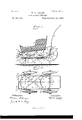
- I attain this end by the mechanism illustrated in the acco1npanying drawings on two sheets, in which a childs convertible carriage is shown by preference, and in which- Figure 1 is a side elevation of achilt scarriage, showing its runner parts in contact with the ground.
- Fig. 2 is a plan View of the same, the box being removed in order to afford a clearer view.
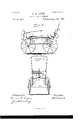
- Fig. 3 is an elevation of Fig. 1, taken from the same point of view, but with the box removed and the wheel parts in con tact with the ground; and
- Fig. 4 is an end elevation of Fig. 3, taken from the rear.
- A is substantially the frame work, and it is forwardly bent upward and extended rearward for a sufticient distance, thus form ing a spring-support, B, for the box 0.
- the frame A is extended on either side of the box and below it into two members,which are suitably held in the required position by means of the tics D, which are placed near either end thereof, and by the compound X-brace E, centrally located thereon.
- Sleigh-runners F are substantially secured to the under side of the frame-work A by means of suitable posts, G, which are secured thereto at their bottom ends, their upper ends being provided with shoulders, upon which rest the ends of the ties D and the ends of the compound X-brace E, and with threaded ends .vided and hung in the boxes d d.
- the forward ends of the runners F are up wardly curved and riveted to the frame-work A at Z), and tied together by the tie-rod c.
- I On the under side of the members of the frame-work A, I provide, in a suitable position at the forward and rearward ends of the same, bearings (2 cl, the same being secured to the frame-work A by nuts and bolt e e e e, &c.
- At the rear end of the framework I provide an arch-piece, H, (the office of which I will presently describe,) and the upwardly -extended driving-handle J.
- the lower ends of the said arch-piece H and of the driving-handle J are secured to the rear of the frame work A by the same rearward nuts and bolts, 6 e, that secure the rearward boxes, (1, to said frame-work A.
- axles K K are pro Inside of the frame-work A the said axles K K have a curved form, as well shown in Fig. 2. Outside the frame-work A the said axles K Kare extended at nearly right angles to the curved inside portions thereof, and terminate in suitable bearings for the wheels L L L L.
- a reach, M is provided and hinged to the central curved portions of the axles K K by the boxesff, provided for that purpose.
- the reach M serves to assure uniformity of posi- -tion between the forward and rearward axles during the operation of convertibility.
- the said reach M is extended at its rearward end into a seat, g, the objectof which will be pressently described.
- a locking-piece 1, at i.
- This locking-piece h is extended at its upper end into a hand-loop, and at its lower end into a notched circular or cam bearing, which in operation, when the wheels are on the ground, is brought to bear on the seat gof the reach M, thus securing the 5 wheels and their axles in working posit-ion when so desired.
- I substantially secure a spring catch-piece, 7a, which serves to hold the wheels off the ground when the sleigh-runners are desired for use.
- This is accomplished by connecting the ends of the rear axle, K, by means of a connectingpiece, 1?, which is suitably riveted thereto at either end. It will thus be seen that when the wheels are thrown off the ground and upward that the spring catch-piece It may be brought into action with the connecting-piece P, and
- the foot of the operator may release the spring catch-piece from its engagement with the connecting-piece P, and by simply pressing downward with the hands on the driving-handle J thus convert the vehicle from runner into wheeled parts, and assure this position by means of the pivoted locking-piece h on the arch H.
Landscapes
- Engineering & Computer Science (AREA)
- Chemical & Material Sciences (AREA)
- Combustion & Propulsion (AREA)
- Transportation (AREA)
- Mechanical Engineering (AREA)
- Agricultural Machines (AREA)
Description
2 Sheets-Sheet-1.
(No Model;)
W. H. YATES.
CONVERTIBLE VEHICLE.
PatentedApr. 24, 1888.
(No Model.) v 2 Sheets- -Sheet 2. W. H. YATES.
CONVERTIBLE VEHICLE. No. 381,663. 7 Patented Apr. 24, 1888.
llllllll I h Wfined 6:5. r [730673505 72M 4. W oil 8- %MM, KL
UNTTED STATES PATENT @EETbE.
YVILLIAM H. YATES, OF AUBURN, NEW YORK, ASSIGNOR OF ONE-THIRD TO SAMUEL B. SPILLER, OF SAME PLACE.
CONVERTIBLE VEHICLE.
SPECIFICATION forming part of Letters Patent No. 381,663, dated April 24, 1 88.
Application filed February 21, 1888. Serial No. 264.851. (No model.)
To aZZ whom it may concern.-
Be it known that 1, WILLIAM H. Yxrns, a citizen of the United States, residing in the city of Auburn, county of Cayuga, and State of New York, have invented new and useful Improvements in Convertible Vehicles, of which the following is a specification.
My invention relates to improvements in convertible vehicles, in which sleigh-runners and wheels are so combined and arranged together as to be quickly and readily substituted for each other as the exigencies of the season or the condition of the ground may require; and the object of my invention is to so construct the several parts as to preclude any delay in the conversion of the runner to the wheel parts, or vice versa. I attain this end by the mechanism illustrated in the acco1npanying drawings on two sheets, in which a childs convertible carriage is shown by preference, and in which- Figure 1 is a side elevation of achilt scarriage, showing its runner parts in contact with the ground. Fig. 2 is a plan View of the same, the box being removed in order to afford a clearer view. Fig. 3 is an elevation of Fig. 1, taken from the same point of view, but with the box removed and the wheel parts in con tact with the ground; and Fig. 4 is an end elevation of Fig. 3, taken from the rear.
Similarletters refer to similar parts throughout the several views.
In Fig. 1, A is substantially the frame work, and it is forwardly bent upward and extended rearward for a sufticient distance, thus form ing a spring-support, B, for the box 0.
The frame A is extended on either side of the box and below it into two members,which are suitably held in the required position by means of the tics D, which are placed near either end thereof, and by the compound X-brace E, centrally located thereon.
Sleigh-runners F are substantially secured to the under side of the frame-work A by means of suitable posts, G, which are secured thereto at their bottom ends, their upper ends being provided with shoulders, upon which rest the ends of the ties D and the ends of the compound X-brace E, and with threaded ends .vided and hung in the boxes d d.
passing through the ends of the said ties and compound brace and through the frame-work A, when the whole is substantially held in working position by means of the nuts a a a a.
The forward ends of the runners F are up wardly curved and riveted to the frame-work A at Z), and tied together by the tie-rod c. On the under side of the members of the frame-work A, I provide, in a suitable position at the forward and rearward ends of the same, bearings (2 cl, the same being secured to the frame-work A by nuts and bolt e e e e, &c. At the rear end of the framework I provide an arch-piece, H, (the office of which I will presently describe,) and the upwardly -extended driving-handle J. The lower ends of the said arch-piece H and of the driving-handle J, are secured to the rear of the frame work A by the same rearward nuts and bolts, 6 e, that secure the rearward boxes, (1, to said frame-work A.
Forward and rearward axles K K are pro Inside of the frame-work A the said axles K K have a curved form, as well shown in Fig. 2. Outside the frame-work A the said axles K Kare extended at nearly right angles to the curved inside portions thereof, and terminate in suitable bearings for the wheels L L L L.
A reach, M, is provided and hinged to the central curved portions of the axles K K by the boxesff, provided for that purpose. The reach M serves to assure uniformity of posi- -tion between the forward and rearward axles during the operation of convertibility. The said reach M is extended at its rearward end into a seat, g, the objectof which will be pressently described.
At the center of the arch-piece H, at the rear end of the frame work A, is pivoted a locking-piece, 1, at i. This locking-piece h is extended at its upper end into a hand-loop, and at its lower end into a notched circular or cam bearing, which in operation, when the wheels are on the ground, is brought to bear on the seat gof the reach M, thus securing the 5 wheels and their axles in working posit-ion when so desired.
At a convenient point on the arch-piece H,
I substantially secure a spring catch-piece, 7a, which serves to hold the wheels off the ground when the sleigh-runners are desired for use. This is accomplished by connecting the ends of the rear axle, K, by means of a connectingpiece, 1?, which is suitably riveted thereto at either end. It will thus be seen that when the wheels are thrown off the ground and upward that the spring catch-piece It may be brought into action with the connecting-piece P, and
.thus serve to hold the wheels up and off the ground. When it is desired to reverse this action,(bringing the wheels to the ground and the sleigh-runners off the same,) the foot of the operator may release the spring catch-piece from its engagement with the connecting-piece P, and by simply pressing downward with the hands on the driving-handle J thus convert the vehicle from runner into wheeled parts, and assure this position by means of the pivoted locking-piece h on the arch H.
Having thus described the construction and i the operation of the several parts of my imbeyond the same, and carrying on their outer ends arms to which wheels are pivoted, the whole being so arranged and combined that by the partial rotation of the rock-shafts in one direction the whole will be supported and carried on the wheels, and by rotating in the downward and forward to bring the wheels in Working position, substantially as described and shown.
4. The runner-supported frame carrying a childs-carriage body supported on springs, the cranked rock-shafts having arms at their outer ends, to which wheels are pivoted, said rock-shafts being supported by bearings, and having a link-piece connecting the cranked parts of said shafts together above their axis of rotation,substantiall y in the manner described andshown.
5. The runner supported frame carrying a childscarriage body supported on springs, the cranked rock'shafts, the link-piece M, connecting the same together, in combination with the locking mechanism for holding the same in the several adjusted positions,substantially as and for the purpose stated.
6. The combination of the connecting-piece P with the arms of the rear axles, the archpiece H, and the catch K, as and for the pur pose stated.
In testimony whereof I'have hereunto set my hand this 11th day of February, 1888.
WM. H. YATES.
WVitnesses:
lVIARIAN G. CULVER, J EWETT M. DE LONG.
Publications (1)
| Publication Number | Publication Date |
|---|---|
| US381663A true US381663A (en) | 1888-04-24 |
Family
ID=2450657
Family Applications (1)
| Application Number | Title | Priority Date | Filing Date |
|---|---|---|---|
| US381663D Expired - Lifetime US381663A (en) | yate s |
Country Status (1)
| Country | Link |
|---|---|
| US (1) | US381663A (en) |
-
0
- US US381663D patent/US381663A/en not_active Expired - Lifetime
Similar Documents
| Publication | Publication Date | Title |
|---|---|---|
| US1750187A (en) | Power coaster | |
| US381663A (en) | yate s | |
| US1018696A (en) | Can-carrier. | |
| US730193A (en) | Bicycle trailer package-carrier. | |
| US1060649A (en) | Support and lock for cycles. | |
| US365471A (en) | Wheel attachment for sleighs | |
| US411319A (en) | Wheelbarrow | |
| US302398A (en) | Tricycle | |
| US1245004A (en) | Truck. | |
| US1125571A (en) | Hand-truck. | |
| US410681A (en) | James logan watkins | |
| US1212243A (en) | Go-cart. | |
| US1193170A (en) | Automobile sleigh | |
| US393076A (en) | Combined runner and wheeled vehicle | |
| US400381A (en) | Sleigh-runner for wheeled vehicles | |
| US307020A (en) | cummins | |
| US279541A (en) | Velocipede | |
| US1259127A (en) | Mail vehicle or wagon. | |
| US780808A (en) | Go-cart. | |
| US1192081A (en) | Combined wagon and velocipede. | |
| US1023618A (en) | Vehicle-support. | |
| US441151A (en) | Vehicle | |
| US808261A (en) | Lumber-wagon. | |
| US1160397A (en) | Motor-cycle stand. | |
| US1706245A (en) | Vehicle |