US3815744A - Filter construction - Google Patents
Filter construction Download PDFInfo
- Publication number
- US3815744A US3815744A US00320473A US32047373A US3815744A US 3815744 A US3815744 A US 3815744A US 00320473 A US00320473 A US 00320473A US 32047373 A US32047373 A US 32047373A US 3815744 A US3815744 A US 3815744A
- Authority
- US
- United States
- Prior art keywords
- combination
- filter element
- caps
- casing
- threaded
- Prior art date
- Legal status (The legal status is an assumption and is not a legal conclusion. Google has not performed a legal analysis and makes no representation as to the accuracy of the status listed.)
- Expired - Lifetime
Links
- 238000010276 construction Methods 0.000 title description 7
- 230000000717 retained effect Effects 0.000 claims abstract description 10
- 230000002093 peripheral effect Effects 0.000 claims abstract description 6
- 210000002445 nipple Anatomy 0.000 claims description 3
- 239000000446 fuel Substances 0.000 abstract description 9
- 239000000463 material Substances 0.000 description 3
- 230000001681 protective effect Effects 0.000 description 3
- 238000007789 sealing Methods 0.000 description 3
- 229920001971 elastomer Polymers 0.000 description 2
- 238000004519 manufacturing process Methods 0.000 description 2
- 239000003795 chemical substances by application Substances 0.000 description 1
- 239000000806 elastomer Substances 0.000 description 1
- 238000001914 filtration Methods 0.000 description 1
- 239000012530 fluid Substances 0.000 description 1
- 239000007789 gas Substances 0.000 description 1
- 239000012535 impurity Substances 0.000 description 1
- 239000007788 liquid Substances 0.000 description 1
- 230000014759 maintenance of location Effects 0.000 description 1
- 229920003023 plastic Polymers 0.000 description 1
Images
Classifications
-
- B—PERFORMING OPERATIONS; TRANSPORTING
- B01—PHYSICAL OR CHEMICAL PROCESSES OR APPARATUS IN GENERAL
- B01D—SEPARATION
- B01D35/00—Filtering devices having features not specifically covered by groups B01D24/00 - B01D33/00, or for applications not specifically covered by groups B01D24/00 - B01D33/00; Auxiliary devices for filtration; Filter housing constructions
- B01D35/02—Filters adapted for location in special places, e.g. pipe-lines, pumps, stop-cocks
Definitions
- the filter construction comprises an elongated rod-like body having opposite end portions with lengthwise extending reliefs at opposite sides, the end portions also having peripheral thread sections which are circumferentially interrupted by the reliefs; internally threaded caps mounted on the body thread sections to bound the reliefs; a porous tubular filter element through which the body projects; the body having a closure to close one end of the filter element for retention between that closure and one of the end caps closing the opposite end of the element, one body end portion relief then having'direct communication with the outside of the filter element, and the other body end portion relief then having direct communication with the inside of the filter element; and a casing having opposite ends retained at the end caps and within which the body projects.
- the reliefs and their relation to the remainder of the filter simplify the fabrication of the filter, and enhance its flow characteristics.
- the body cross section at the relief locus has I-shape, as will be seen.
- Additional objects include the provision of a protective clip received over the casing to be forcibly rotated about the latter, the clip defining an aperture for viewing of a transparent portion of the casing, as will be seen.
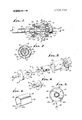
- FIG. 1 is a side elevation, in section
- FIG. 2 is a section on lines 22 of FIG. 1;
- FIG. 3 is an axially exploded perspective view of the FIG. 1 filter
- FIG. 4 is a perspective showing of a clip receivable over the filter
- FIG. 5 is an end elevation showing the clip attached to the filter.
- FIG. 6 is a fragmentary perspective view of a modified body.
- the fluid filter shown in the drawing comprises an elongated rod-like body 10 having opposite end portions 11 and 12.
- the latter have lengthwise extending reliefs 13 (such as are defined by flats 13a) at their opposite sides, as well as peripheral thread sections 14 circumferentially interrupted by the reliefs.
- Cap 15 includes a projecting tubular terminal defining a nipple 19 to receive a hose 20, whereas body 16 defines a projecting tubular terminal 21 which is internally threadedto receive an externally threaded pipe 22. It will be understood that one or both ends of the filter may receive either or both of the caps 15 and 16.
- Each end cap may also include polygonal shoulders 24 to be wrench gripped, and a flange 26 grooved at 27 to receive a sealing O-ring 28 typically made of rubber or an elastomer.
- a tubular casing 29 has opposite ends 30 and 31 in annular sealing engagement with the O ring seals, the clamping or sealing force being controlled by relatively advancing or retracting one or both end caps, as afforded by turning the end cap by means of a wrench applied to shoulders 24.
- the casing may for example consist of high-impact transparent plastic material, and the ends thereof are centered by the shoulder 32 at the grooving 27.
- Body 10 has a closure 33 thereon to close one end of a porous tubular filter element 34 through which the body projects, the closure typically taking the form of a flange integral with the metallic body.
- the element 34 is endwise retained between the closure and one of the end caps closing off the opposite end of the filter element at 35.
- the end cap has shoulders at 36 for locating the corresponding end of the filter element in coaxial alignment with the axis of body 10.
- the filter element itself may-be made of any suitable porous, filtering material.
- One highly advantageous material is identified by the trademark Microbon, and is supplied by the Bendix Corporation.
- FIGS. 4 and 5 illustrate the provision of a spring clip or sleeve 43 which is U-shaped with curvature to closely conform to the cylindrical or tubular configuration of the transparent casing 29.
- the protective (as for example metallic) clip snaps over the casing, as in FIG. 5, and may be forcibly rotated to any angularposition so that the apertureor gap 44 between the clip turned terminals 43a may be brought into the line of sight 45 of the viewer. This enables ready viewing when the filter is installed in a fuel line, as within the engine compartment of an automobile.
- End tangs 46 attach over the end caps 26 against which the clip has frictional en gagement.
- FIG. 6 shows a modified end portion 50 of the rod-like body 10, and which is generally I-shaped in cross section.
- the end portion is endwise slotted or milled at opposite sides of the body (for rapid production and maximum flow) to define two elongated side openings 51 intersecting the tip 52 of the end portion.
- each opening 51 exceeds that of the interruped external threading 53 on the end portion, and slot wall curvature at 54 guides the flow laterally away from or toward the body and the slot.
- the casing or housing 29 may be metallic.
- a filter comprising a. an elongated rod-like body having opposite end portions each of which has endwise extending slots at opposite sides thereof to define two elongated side openings intersecting the tip of each said portion, said end portions also having peripheral thread sections circumferentially interrupted by said openings, the length of each said opening exceeding the length of the thread section interrupted thereby,
- the body having a closure thereon to close one end of the filter element so that the element is retained between said closure and one of said end caps closing the opposite end of said element, one body end portion openings then having direct communication with the outside of the filter element and the 4 other body end portion openings then having direct communication with the inside of the filter element, and
- each cap has a projecting tubular terminal which is threaded to receive a threaded fitting.
Landscapes
- Chemical & Material Sciences (AREA)
- Chemical Kinetics & Catalysis (AREA)
- Filtration Of Liquid (AREA)
Abstract
A fuel filter comprises: A. AN ELONGATED ROD-LIKE BODY HAVING OPPOSITE END PORTIONS WHICH HAVE LENGTHWISE EXTENDING RELIEFS AT THE SIDES THEREOF, SAID END PORTIONS ALSO HAVING PERIPHERAL THREAD SECTIONS CIRCUMFERENTIALLY INTERRUPTED BY SAID RELIEFS, B. THREADED CAPS MOUNTED ON SAID BODY THREAD SECTIONS TO EXTEND ABOUT THE RELIEFS, C. A POROUS TUBULAR FILTER ELEMENT THROUGH WHICH THE BODY PROJECTS, D. THE BODY HAVING A CLOSURE THEREON TO CLOSE ONE END OF THE FILTER ELEMENT SO THAT THE ELEMENT IS RETAINED BETWEEN SAID CLOSURE AND ONE OF SAID END CAPS CLOSING THE OPPOSITE END OF SAID ELEMENT, ONE BODY END PORTION RELIEF THEN HAVING DIRECT COMMUNCIATION WITH THE OUTSIDE OF THE FILTER ELEMENT AND THE OTHER BODY END PORTION RELIEF THEN HAVING DIRECT COMMUNICATION WITH THE INSIDE OF THE FILTER ELEMENT, AND E. A CASING HAVING OPPOSITE ENDS RETAINED AT SAID END CAPS AND WITHIN WHICH SAID BODY PROJECTS.
Description
United States Patent 1 1 1111 3,815,744 Vanderpoel June 11, 1974 1 FILTER CONSTRUCTION [57] ABSTRACT [76] Inventor: Albert G. H. Vanderpoel, 1126 Brightglen Cir., Westlake Village. A fuel filter Comprises: Calif 91361 a. an elongated rodl1ke body having oppos1te end portions which have lengthwise extending reliefs at the i 1 Flledi Jan- 2, 1973 sides thereof. said end portions'also having peripheral [2]] App}. No 320 473 thread sections circumferentially interrupted by said reliefs,
b. threaded caps mounted on said body thread [52] US. Cl 210/94, 22llO/243428. 22135144523), Sections to extend about the reliefs [51] 1m. (:1 1301a 35/02 a P tubular filter element through which the 58 Field of Search 210/94, 95, 232, 442, 446, body proiects,
210/448, 453 d. the body having a closure thereon to close one end of the filter element so that the element is retained [56] References Cited between said closure and one of said end caps closing UNITED STATES PATENTS the opposite end of said element, one body end 2 265 550 12/194] Smith i 210/94 portion relief then having direct communciation with 217931752 5/1957 Jay....i..iiiiii.iiiii..:iiiLiam/448 xthe Outside filter element and thiei'h'ther body 3,317,043 5/1967 Vandel'p06l 210/94 end Portion relief than having dire Communication 3.369.665 2/1968 Paulson 210 94 with the inside of the filter element, and
FOREIGN PATENTS QR P I T N e. a casing having opposite ends retained at said end 225.850 11/1959 Australia 210/94 caps and whch body Prolects- Primary ExaminerJohn Adee Assistant ExaminerRobert H. Spitzer Attorney, Agent, or Firm-William W. Haefliger 8 Claims, 6 Drawing Figures a0 29 5'1 2/ 26 25 '5 2O J I I ,.J Y i 35 FILTER CONSTRUCTION BACKGROUND OF THE INVENTION This invention relates generally to fuel filters, and more particularly concerns in-line type filters such as may be used for example to filter gasoline as well as other fuels and gases. I
In my US. Pat. No. 3,317,043 I described a fuel filter of highly advantageous construction and mode of operation. The present invention adds to the utility of that filter in that the construction is simplified, the flow is enchanced, and a protective shield is applied to the device, while permitting viewing of the contents of the filter, as before. The prior art, to my knowledge, lacks the construction, mode operation and results now afforded by the improved filter.
SUMMARY OF THE INVENTION Basically, the filter construction comprises an elongated rod-like body having opposite end portions with lengthwise extending reliefs at opposite sides, the end portions also having peripheral thread sections which are circumferentially interrupted by the reliefs; internally threaded caps mounted on the body thread sections to bound the reliefs; a porous tubular filter element through which the body projects; the body having a closure to close one end of the filter element for retention between that closure and one of the end caps closing the opposite end of the element, one body end portion relief then having'direct communication with the outside of the filter element, and the other body end portion relief then having direct communication with the inside of the filter element; and a casing having opposite ends retained at the end caps and within which the body projects. As a result, the reliefs and their relation to the remainder of the filter simplify the fabrication of the filter, and enhance its flow characteristics. In one form of the invention, the body cross section at the relief locus has I-shape, as will be seen.
Additional objects include the provision of a protective clip received over the casing to be forcibly rotated about the latter, the clip defining an aperture for viewing of a transparent portion of the casing, as will be seen.
These and other objects and advantages of the invention, as well as the details of an illustrative embodiment, will be more fully understood from the following description and drawings, in which:
DRAWING DESCRIPTION FIG. 1 is a side elevation, in section;
FIG. 2 is a section on lines 22 of FIG. 1;
FIG. 3 is an axially exploded perspective view of the FIG. 1 filter;
FIG. 4 is a perspective showing of a clip receivable over the filter;
FIG. 5 is an end elevation showing the clip attached to the filter; and
FIG. 6 is a fragmentary perspective view of a modified body.
DETAILED DESCRIPTION The fluid filter shown in the drawing comprises an elongated rod-like body 10 having opposite end portions 11 and 12. The latter have lengthwise extending reliefs 13 (such as are defined by flats 13a) at their opposite sides, as well as peripheral thread sections 14 circumferentially interrupted by the reliefs.
Each end cap may also include polygonal shoulders 24 to be wrench gripped, and a flange 26 grooved at 27 to receive a sealing O-ring 28 typically made of rubber or an elastomer. A tubular casing 29 has opposite ends 30 and 31 in annular sealing engagement with the O ring seals, the clamping or sealing force being controlled by relatively advancing or retracting one or both end caps, as afforded by turning the end cap by means of a wrench applied to shoulders 24. The casing may for example consist of high-impact transparent plastic material, and the ends thereof are centered by the shoulder 32 at the grooving 27.
In this regard, fuel flows through body end portion reliefs 13 into the space 40 at the outside of the filter element; the fuel then flows radially through the element and into the space 41 at the inside thereof, to exit via body end portion reliefs and to the right, in FIG. 1. Accordingly, impurities in the fuel can be observed in space 40 through the case 29, and the user can readily see when it is necessary to disassemble the filter and clean same. The filter element itself may-be made of any suitable porous, filtering material. One highly advantageous material is identified by the trademark Microbon, and is supplied by the Bendix Corporation.
FIGS. 4 and 5 illustrate the provision of a spring clip or sleeve 43 which is U-shaped with curvature to closely conform to the cylindrical or tubular configuration of the transparent casing 29. The protective (as for example metallic) clip snaps over the casing, as in FIG. 5, and may be forcibly rotated to any angularposition so that the apertureor gap 44 between the clip turned terminals 43a may be brought into the line of sight 45 of the viewer. This enables ready viewing when the filter is installed in a fuel line, as within the engine compartment of an automobile. End tangs 46 attach over the end caps 26 against which the clip has frictional en gagement.
Finally, FIG. 6 shows a modified end portion 50 of the rod-like body 10, and which is generally I-shaped in cross section. The end portion is endwise slotted or milled at opposite sides of the body (for rapid production and maximum flow) to define two elongated side openings 51 intersecting the tip 52 of the end portion.
' 3 The length of each opening 51 exceeds that of the interruped external threading 53 on the end portion, and slot wall curvature at 54 guides the flow laterally away from or toward the body and the slot.
If desired, the casing or housing 29 may be metallic.
I claim:
1. A filter comprising a. an elongated rod-like body having opposite end portions each of which has endwise extending slots at opposite sides thereof to define two elongated side openings intersecting the tip of each said portion, said end portions also having peripheral thread sections circumferentially interrupted by said openings, the length of each said opening exceeding the length of the thread section interrupted thereby,
b. threaded caps mounted on said body thread sections to extend about the reliefs,
c. a porous tubular filter element through which the body projects,
d. the body having a closure thereon to close one end of the filter element so that the element is retained between said closure and one of said end caps closing the opposite end of said element, one body end portion openings then having direct communication with the outside of the filter element and the 4 other body end portion openings then having direct communication with the inside of the filter element, and
e. a casing having opposite ends retained at said end caps and within which said body projects.
2. The combination of claim 1 wherein at least one of the caps has a projecting tubular terminal which is threaded to receive a threaded fitting.
3. The combination of claim 2 wherein the other cap has a projecting tubular terminal which defines a hose nipple.
4. The combination of claim 1 wherein each cap has a projecting tubular terminal which is threaded to receive a threaded fitting.
5. The combination of claim 1 including a protection clip received over said casing to be forcibly rotatable therearound, the clip defining an. aperture through which a transparent portion of the casing may be viewed.
6. The combination of claim 5 wherein the clip is U- shaped and spring urged to resist sideward dislodgement off the casing.
7. The combination of claim 5 wherein the clip has opposite end attachment to said caps.
8. The combination of claim 1 wherein said body end portions have I-shaped cross sections.
Claims (8)
1. A filter comprising a. an elongated rod-like body having opposite end portions each of which has endwise extending slots at opposite sides thereof to define two elongated side openings intersecting the tip of each said portion, said end portions also having peripheral thread sections circumferentially interrupted by said openings, the length of each said opening exceeding the length of the thread section interrupted thereby, b. threaded caps mounted on said body thread sections to extend about the reliefs, c. a porous tubular filter element through which the body projects, d. the body having a closure thereon to close one end of the filter element so that the element is retained between said closure and one of said end caps closing the opposite end of said element, one body end portion openings then having direct communication with the outside of the filter element and the other body end portion openings then having direct communication with the inside of the filter element, and e. a casing having opposite ends retained at said end caps and within which said body projects.
2. The combination of claim 1 wherein at least one of the caps has a projecting tubular terminal which is threaded to receive a threaded fitting.
3. The combination of claim 2 wherein the other cap has a projecting tubular terminal which defines a hose nipple.
4. The combination of claim 1 wherein each cap has a projecting tubular terminal which is threaded to receive a threaded fitting.
5. The combination of claim 1 including a protection clip received over said casing to be forcibly rotatable therearound, the clip defining an aperture through which a transparent portion of the casing may be viewed.
6. The combination of claim 5 wherein the clip is U-shaped and spring urged to resist sideward dislodgement off the casing.
7. The combination of claim 5 wherein the clip has opposite end attachment to said caps.
8. The combination of claim 1 wherein said body end portions have I-shaped cross sections.
Priority Applications (1)
| Application Number | Priority Date | Filing Date | Title |
|---|---|---|---|
| US00320473A US3815744A (en) | 1973-01-02 | 1973-01-02 | Filter construction |
Applications Claiming Priority (1)
| Application Number | Priority Date | Filing Date | Title |
|---|---|---|---|
| US00320473A US3815744A (en) | 1973-01-02 | 1973-01-02 | Filter construction |
Publications (1)
| Publication Number | Publication Date |
|---|---|
| US3815744A true US3815744A (en) | 1974-06-11 |
Family
ID=23246580
Family Applications (1)
| Application Number | Title | Priority Date | Filing Date |
|---|---|---|---|
| US00320473A Expired - Lifetime US3815744A (en) | 1973-01-02 | 1973-01-02 | Filter construction |
Country Status (1)
| Country | Link |
|---|---|
| US (1) | US3815744A (en) |
Cited By (12)
| Publication number | Priority date | Publication date | Assignee | Title |
|---|---|---|---|---|
| US4062781A (en) * | 1976-06-04 | 1977-12-13 | Whatman Reeve Angel Limited | Disposable filter with interchangeable end elements |
| USD248485S (en) * | 1977-04-18 | 1978-07-11 | Whatman Reeve Angel Limited | Filter |
| US4400187A (en) * | 1980-03-28 | 1983-08-23 | Roy E. Coffman | Device for preventing circulation of liquid water entrained in compressed air |
| US4493717A (en) * | 1982-05-06 | 1985-01-15 | Berger Jr L Joseph | In-line disposable filter |
| US4759842A (en) * | 1986-12-04 | 1988-07-26 | David Frees | In-line fuel filtering device |
| EP0290787A1 (en) * | 1987-05-09 | 1988-11-17 | Robert Bosch Gmbh | Damper element for pulsating liquid-flows |
| US5928510A (en) * | 1997-11-20 | 1999-07-27 | Miller Brewing Company | Filter apparatus for even flow distribution |
| US20030111396A1 (en) * | 2001-03-07 | 2003-06-19 | Smith Paul B. | Fluid filter with pressure relief valve |
| US20090139915A1 (en) * | 2000-07-25 | 2009-06-04 | Davco Technology, Llc | Fluid Filter with Pressure Relief Valve and Bypass Valve |
| US20110062061A1 (en) * | 2009-09-17 | 2011-03-17 | Davco Technology, Llc | Filter Assembly with Modular Relief Valve Interface |
| US20140102680A1 (en) * | 2012-10-17 | 2014-04-17 | Lee Supa-Products Industrial Co., Ltd. | Radiator Filter For Automobile |
| US20140116966A1 (en) * | 2012-10-31 | 2014-05-01 | Robert Dennis Podsadowski | High pressure fluid filter system |
Citations (4)
| Publication number | Priority date | Publication date | Assignee | Title |
|---|---|---|---|---|
| US2265550A (en) * | 1940-07-03 | 1941-12-09 | D B Smith & Company Inc | Strainer |
| US2793752A (en) * | 1954-09-07 | 1957-05-28 | A V Roe Canada Ltd | Full flow inline filter |
| US3317043A (en) * | 1965-03-31 | 1967-05-02 | Albert G H Vanderpoel | In-line filter construction |
| US3369665A (en) * | 1967-04-27 | 1968-02-20 | Universal Oil Prod Co | Tubular filter with sliding casing |
-
1973
- 1973-01-02 US US00320473A patent/US3815744A/en not_active Expired - Lifetime
Patent Citations (4)
| Publication number | Priority date | Publication date | Assignee | Title |
|---|---|---|---|---|
| US2265550A (en) * | 1940-07-03 | 1941-12-09 | D B Smith & Company Inc | Strainer |
| US2793752A (en) * | 1954-09-07 | 1957-05-28 | A V Roe Canada Ltd | Full flow inline filter |
| US3317043A (en) * | 1965-03-31 | 1967-05-02 | Albert G H Vanderpoel | In-line filter construction |
| US3369665A (en) * | 1967-04-27 | 1968-02-20 | Universal Oil Prod Co | Tubular filter with sliding casing |
Cited By (19)
| Publication number | Priority date | Publication date | Assignee | Title |
|---|---|---|---|---|
| US4062781A (en) * | 1976-06-04 | 1977-12-13 | Whatman Reeve Angel Limited | Disposable filter with interchangeable end elements |
| USD248485S (en) * | 1977-04-18 | 1978-07-11 | Whatman Reeve Angel Limited | Filter |
| US4400187A (en) * | 1980-03-28 | 1983-08-23 | Roy E. Coffman | Device for preventing circulation of liquid water entrained in compressed air |
| US4493717A (en) * | 1982-05-06 | 1985-01-15 | Berger Jr L Joseph | In-line disposable filter |
| US4759842A (en) * | 1986-12-04 | 1988-07-26 | David Frees | In-line fuel filtering device |
| EP0290787A1 (en) * | 1987-05-09 | 1988-11-17 | Robert Bosch Gmbh | Damper element for pulsating liquid-flows |
| US5928510A (en) * | 1997-11-20 | 1999-07-27 | Miller Brewing Company | Filter apparatus for even flow distribution |
| US20110017658A1 (en) * | 2000-07-25 | 2011-01-27 | Davco Technology, Llc | Filter Cartridge with Pressure Relief Valve |
| US20090065411A1 (en) * | 2000-07-25 | 2009-03-12 | Davco Technology, Llc | Filter Cartridge with Pressure Relief Valve |
| US20090139915A1 (en) * | 2000-07-25 | 2009-06-04 | Davco Technology, Llc | Fluid Filter with Pressure Relief Valve and Bypass Valve |
| US7854837B2 (en) | 2000-07-25 | 2010-12-21 | Davco Technology, Llc | Filter cartridge with pressure relief valve |
| US9079129B2 (en) | 2000-07-25 | 2015-07-14 | Davco Technology, Llc | Filter cartridge with divider |
| US6841065B2 (en) | 2001-03-07 | 2005-01-11 | Davco Manufacturing, L.L.C. | Fluid filter with pressure relief valve |
| US20030111396A1 (en) * | 2001-03-07 | 2003-06-19 | Smith Paul B. | Fluid filter with pressure relief valve |
| US20110062061A1 (en) * | 2009-09-17 | 2011-03-17 | Davco Technology, Llc | Filter Assembly with Modular Relief Valve Interface |
| US8574430B2 (en) | 2009-09-17 | 2013-11-05 | Davco Technology, Llc | Filter assembly with modular relief valve interface |
| US9586163B2 (en) | 2009-09-17 | 2017-03-07 | Davco Technology, Llc | Filter assembly with modular relief valve interface |
| US20140102680A1 (en) * | 2012-10-17 | 2014-04-17 | Lee Supa-Products Industrial Co., Ltd. | Radiator Filter For Automobile |
| US20140116966A1 (en) * | 2012-10-31 | 2014-05-01 | Robert Dennis Podsadowski | High pressure fluid filter system |
Similar Documents
| Publication | Publication Date | Title |
|---|---|---|
| US3815744A (en) | Filter construction | |
| US3317043A (en) | In-line filter construction | |
| US3540594A (en) | Oil filter adapter | |
| US3847819A (en) | Seal for fluid filter | |
| US6024229A (en) | Reusable filter assembly | |
| US3250395A (en) | Chromatographic columns | |
| US3759062A (en) | Receiver drier housing for automobile air conditioning systems | |
| US4032311A (en) | Tank filter | |
| US4758340A (en) | Sealing device for a chromatography column | |
| US2979208A (en) | Fluid line supported filter and filter mounting | |
| GB1028986A (en) | Liquid filter assemblies | |
| US3327858A (en) | In-line filter device | |
| US4728421A (en) | Filter apparatus for utilization with hollow cylindrical filter elements | |
| US2145535A (en) | Filter | |
| US2605904A (en) | Oil filter | |
| US4970817A (en) | Vehicle remote oil fill apparatus | |
| US2995250A (en) | Oil filter | |
| US3926815A (en) | Readily attachable water filter with cutoff valve | |
| GB1362715A (en) | Spin-on type filters | |
| US4131547A (en) | Refillable column for chromatography at elevated pressure | |
| US3776263A (en) | Fuel cut-off lock | |
| US2774947A (en) | Sealing means on fixtures for fluorescent tubes | |
| GB982466A (en) | Filters for liquids | |
| US6444123B1 (en) | Magnetic oil filtering apparatus | |
| US3197029A (en) | Filter |