US3802054A - Sealer for foodstuff packages - Google Patents
Sealer for foodstuff packages Download PDFInfo
- Publication number
- US3802054A US3802054A US00194292A US19429271A US3802054A US 3802054 A US3802054 A US 3802054A US 00194292 A US00194292 A US 00194292A US 19429271 A US19429271 A US 19429271A US 3802054 A US3802054 A US 3802054A
- Authority
- US
- United States
- Prior art keywords
- plunger
- staple
- guide
- bag
- anvil
- Prior art date
- Legal status (The legal status is an assumption and is not a legal conclusion. Google has not performed a legal analysis and makes no representation as to the accuracy of the status listed.)
- Expired - Lifetime
Links
Images


Classifications
-
- B—PERFORMING OPERATIONS; TRANSPORTING
- B65—CONVEYING; PACKING; STORING; HANDLING THIN OR FILAMENTARY MATERIAL
- B65B—MACHINES, APPARATUS OR DEVICES FOR, OR METHODS OF, PACKAGING ARTICLES OR MATERIALS; UNPACKING
- B65B51/00—Devices for, or methods of, sealing or securing package folds or closures; Devices for gathering or twisting wrappers, or necks of bags
- B65B51/04—Applying separate sealing or securing members, e.g. clips
-
- Y—GENERAL TAGGING OF NEW TECHNOLOGICAL DEVELOPMENTS; GENERAL TAGGING OF CROSS-SECTIONAL TECHNOLOGIES SPANNING OVER SEVERAL SECTIONS OF THE IPC; TECHNICAL SUBJECTS COVERED BY FORMER USPC CROSS-REFERENCE ART COLLECTIONS [XRACs] AND DIGESTS
- Y10—TECHNICAL SUBJECTS COVERED BY FORMER USPC
- Y10T—TECHNICAL SUBJECTS COVERED BY FORMER US CLASSIFICATION
- Y10T29/00—Metal working
- Y10T29/53—Means to assemble or disassemble
- Y10T29/53709—Overedge assembling means
- Y10T29/53787—Binding or covering
Definitions
- FIG. 1 A first figure.
- the present invention relates to a device for sealing foodstuff packages and other bags by pushing out a channel-shaped staple by a driver and deforming it under pressure.
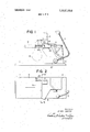
- FIG. 1 is a side-elevational view of a sealer according to the present invention, with a part thereof broken away.
- FIG. 2 is a plan view of the same.
- FIG. 3 is a plan view showing the principal part of the sealer.
- FIGS. 4 and 5 are the views showing the operating condition of the sealer.
- FIG. 6 is a cross sectional view taken along the line VIVI of FIG. 2.
- FIG. 7 is a partially exploded perspective view.
- FIG. 8 is a front view of a clincher section.
- FIG. 9 is a cross sectional view taken along the line IX-IX of FIG. 8.
- FIG. 10 is a side view showing a sealed bag, with a part thereof broken away.
- FIG. I] is a plan view of another embodiment.
- FIG. 12 is a side-elevational view of a sealer provided with a magazine according to still another embodiment.
- FIG. 13 is a plan view showing the principal part of the same.
- FIG. 14 is a vertical cross section of the same.
- FIG. 15 is a partially broken away, exploded perspective view showing the same device from which the magazine is removed.
- A-machine body 2 is detachably mounted on a base plate 1.
- an operation lever 5 for moving a driver 4 through a link mechanism 3.
- a magazine 6 for accommodating channel-shaped staples A, and the lower end of said magazine 6 opens into a driver groove 7 through which the driver 4 slides.
- an L- shaped clincher arm plate 8 is fixed to and projects from the front end of the machine body 2 to form a bag receiving section 9 opening out on one side.
- Reference numeral 10 designates a clincher or anvil attached to the clincher arm plate 8, and a staple bending groove 11, which inclines and forms an angular cross section as illustrated in FIGS. 8 and 9, is provided in said clincher 10.
- One end of a setting lever 12 is formed into a forked resilient member to hold a pin 13 which, in turn, is slidably passed through a circular hole 10a made in the clincher.
- the central portion, of said lever 12 is pivoted to the. clincher arm plate 8 by means of a shaft 14, and one end of a spring 15 wound around said shaft is connected to the head of said pin 13 and the other end thereof to the clincher 10.
- an engaging member 12b which engages with a pin 17 studded at one end to a connecting plate 16.
- a down-bent stopper 16a with which a wing 18a, one of the two wings 18a and 18b protruding under and on both sides of the driver 4, engages.
- Reference numeral 19 designates a staple guide plate whose one end is pivoted to the machine body 2 by means of a shaft 20. And the lower inner edge of said plate 19 is bent downward to form a bent guide member 21 which is engaged with a roller 22 rotatably pivoted to said wing 18b below the driver 4.
- On the other end of the plate 19 is fixed a guide block member 23.
- this guide block member 23 On the side of this guide block member 23 is made a hole 24 through which the pin 13, which passes through and projects from the circular hole 10a in said clincher 10, is passed.
- staple guide grooves 25 and 25 On the inner side of said member 23 and on the side of the bag receiving section 9 of the clincher arm plate 8 are formed staple guide grooves 25 and 25 both leading to the driver groove 7. Said grooves 25 and 25 are formed in such a manner that the inner edges 19a and 8a of the staple guide plate 19 and clincher arm plate 8, respectively, protrude therefrom.
- Reference numerals 26 and 27 designate springs.
- the mouth portion of the bag B is inserted from the side into the bag receiving section 9 and kept in place, and then the operation lever 5 is turned in the direction of the arrow to cause the driver 4 to advance through the link mechanism.
- the roller 22 on the wing 18b slides while pressing the guide member 21 on the staple guide plate 19. This causes said guide plate 19 to rotate about the shaft 20 against the force of the spring 26, thereby closingthe bag receiving section 9 (see FIG. 4).
- the driver 4 breaks off the lowest staple A from the bar of staples contained in the magazine 6 and causes it to slide through the driver groove.
- the staple A further slides through the staple guide grooves 25 and 25 as the driver moves forward, without breaking through the bag which is held by the inner edges 19a and 8a of the staple guide plate and clincher arm plate, respectively, protruding inwards from the staple guide grooves and 25.
- the staple A then contacts the bag B disposed in the bag receiving section 9 and further proceeds while compressing the latter until it reaches the stapler bending groove 11 provided in the clincher 10 where both legs A and A of the staple A are bent along the inclined surface thereof, whereby the legs staggeringly hold the bag B between them without contacting with each other.
- a staple guide plate 41 is pivoted to the machine body 2 by a pin 42 and a link 43 is also pivoted near said base end with the other end of said link 43 being pivoted to a pusher 44.
- a shaft 45 passing slidably through a pusher holder 46 and fitted with a washer 47.
- a spring 48 is provided between the washer 47 and the rear end of the pusher holder 46 to apply a force to pull the pusher 44 toward the left.
- the staple guide plate 41 rotates through the link 43 about the pin 42 to close a bag receiving section 51.
- the driver 49 withdraws and its wing 50 causes the pusher 44 to retreat against the force of the spring 48, whereby the staple guide plate 41 is rotated to open the bag receiving section 51.
- the device according to the present invention is constructed and operated as described above and because of the wide opening in the bag receiving section, it makes it possible not only to smoothly insert and remove the bag thereinto and therefrom but also to keep the bag in the predetermined sealing position by holding the same by closing the staple guide plate.
- the tracks of the staple guide groove which are parallel and straight enable the swift and light movement of the staple.
- the opening and closing of the staple guide plate and the cutting-off and driving of the staple are all achieved by only rotating the operation handle, whereby the sealing operation is effected continuously and automatically.
- the bag is perfectly water-tightly sealed by staple without being damaged by the projected inner edges of the staple guide plate and clincher arm plate during the inserting, sealing and removing operations.
- FIG. 12 and other succeeding drawings illustrate still another embodiment of the staple magazine 6.
- Reference numeral 61 designates a delivery hole provided by perforating square the body 2 above the driver groove 7 in order to send out the staple into the groove 7.
- Item 63 is a magazine holder which is a resilient tubular body with a square cross-section and a longitudinal slot 64. The two adjoining sides of the holder 63 swell inwards to form small projections 65 and 65', while the lower end of one side thereof is extended and bent to form a fitting member 66 adapted to be fixed at one side of a hole 68 made, immediately above the delivery hole 61, in a guide plate 67 mounted on the body 2.
- Item 69 is a chute-like magazine for accomodating staples, channel-shaped in section.
- a staple guide 70 On its inside is provided a staple guide 70, which is also channel-shaped in section, with its one side 70 being fixed to one side 69 of the magazine 69 so that a bar of channel-shaped staples A may be accommodated in a space 71 between the magazine 69 and the staple guide 70.
- the opposite lower ends of said magazine 69 are provided with channel-shaped notches 72 and 7 2, while the adjoining two sides of the same swell outwards, near the lower end, to form small projections 73 and 73 protruding outwards.
- the magazine is installed in the following manner.
- the magazine 69 is inserted from above into the magazine holder 63 until its tip reaches, beyond the small projections 65 and 65' and through the hole 68, the delivery hole 61 in the body 2, the notches 72 and 72 at the lower end of the magazine 69 come into engagement with the stop projections 62 and 62' in the delivery hole 61.
- said small projections 65 and 65 and the small projections 73 and 73 on the magazine 69 exert such forces as to expand the magazine holder 63 so that the magazine 69 may be firmly held by the elasticity of the holder, thereby accomplishing the assembly.
- the device can be made compact for carrying convenience because the magazine 69 is detachable from the body 2.
- the magazine 69 When the magazine 69 is installed, the lower end thereof does not project into the driver groove 7 in such a manner as to prevent the operation of the driver 4, since it is engagedly disposed above the delivery hole 61.
- the magazine holder 63 accurately guides the magazine 69 to the delivery hole 61, and the small projections on the holder 63 and magazine 69 expand the tubular holder so that the magazine 69 is firmly held due to the action of elasticity. So the magazine is securely engaged and held without coming off even if it is subjected to vibration or contact with any other article during the sealing operation.
- the staple A is automatically supplied to the driver groove 7 without requiring the installation of any particular equipment, since it drops into place due to its own weight. Furthermore, it is possible to watch the consumption of staples, thereby preventing the blank driving, since one side of the magazine 69 is cut open. As is evident from the above, this invention offers various excellent results.
- a device for securing the mouth of a bag, as by deforming a staple therearound comprising:
- frame means including a bag receiving section having a notch adapted to receive therein the mouth of a bag, said section having a staple guide groove formed therein along the bottom of said notch; anvil means mounted on said frame means adjacent one side of said notch for coacting with a staple for deforming same;
- driver means for driving a staple into said notch and into engagement with said anvil means, said driver means including a plunger slidably mounted on said frame means for movement toward and away from said anvil means;
- staple guide means swingably mounted on said frame means and swingable between open and closed positions, said guide means including a guide portion disposed for closing the open side of said notch when said guide means is in said closed position, said guide portion having a staple guide groove formed therein, which is substantially parallel to and spaced directly opposite the staple guide groove on said bag receiving section when said guide means is in said closed position;
- locking means coacting between said guide means and said frame means for fixedly interconnecting same when said guide means is in said closed position, said locking means including a movable locking member;
- actuating means coacting between said drive means and said locking member for moving said locking member to a locking position for positively holding said guide means in said closed position when said plunger is being moved toward said anvil means.
- a device wherein said locking member is slidably supported on said anvil means, and wherein said guide means has recess means formed therein and adapted to receive therein an end of said locking member when said guide means is in said closed position and said locking member is in said locking position, whereby said locking member positively mechanically locks said guide means relative to said anvil means.
- actuating means includes means responsive to movement of said plunger toward said anvil means for causing movement of said locking member to said locking position.
- a device further including coupling means coacting between said plunger and said guide means for automatically causing swinging of said guide means toward said closed position when said plunger is moved toward said anvil means.
- said locking member comprises a pinlike member slidably supported relative to said frame means, and said actuating means including movable linkage means drivingly connected between said plunger and said pinlike member for moving same.
- a device wherein said pinlike member is slidably supported on said anvil means and disposed for engaging said guide-means when same is in said closed position, and said movable linkage means including an actuating lever disposed in engagement with said pinlike member and a motion transfer link connected between said lever and said plunger for causing movement of said pinlike member in response to displacement of said plunger.
- a device according to claim 6, wherein said mo tion transfer link and said plunger have cooperating en gageable stops formed thereon and positioned so that the stop on said plunger engages the stop on said motion transfer link upon movement of said plunger away from said anvil means for causing said pinlike member to be moved away from said locking position, and said actuating means further including spring means coacting with said pinlike member for normally resiliently urging same towards said locking position.
- a device further including coupling means coacting between said guide means and said plunger for causing swinging movement of said guide means into said closed position in response to movement of said plunger toward said anvil means.
- said guide portion and said bag receiving section each have a pair of projecting edges disposed on opposite sides of and projecting outwardly from the respective staple guide groove, said edges being adapted to clamp the mouth of the bag therebetween while enabling the staple to be slidably moved into surrounding relationship to the mouth of the bag without penetrating the bag.
- said driver means includes a manually swingable actuating lever pivotally mounted on said frame means and coupled to said plunger for causing linear reciprocating movement of said plunger in response to angular oscillation of said actuating lever.
Abstract
A device for sealing foodstuff packages and other bags using channel-shaped staples, comprising an operation lever for moving a driver, a staple guide plate and a clincher arm plate. When a bag is inserted in a bag receiving section and the operation lever is operated, the driver moves forward to rotate the staple guide plate, which, in turn, closes the bag receiving section and forms parallel staple guide grooves. The driver also pushes out a staple. And then, by further operation of a handle, the staple pushed out by the driver contacts the bag and then reaches a staple bending groove where it is bent to seal the bag.
Description
United States Patent 1191 Takeda Apr. 9, 1974 SEALER FOR FOODSTUFF PACKAGES 3,381,359 5/1968 Schroeder 29/212 1) [75] n ent Se a Takasaki, Jap 3,383,746 5/1968 Narduzzl 53/138 A [73] Assignee: Max Co., Ltd., Tokyo lapan Primary Examiner-Al Lawrence: Smith Assistant Examiner-J. C. Peters [22] Flled 1971 Attorney, Agent, or Firm-Woodlhams, Blanchard and [21] Appl.No.:194,292 1 Flynn [30] Foreign Application Priority Data [57] ABSTRACT Nov. 5 1970 Japanmt. 45-97442 A device for Sealing foodstuff Packages and other bags Nov. 7 1970 Japan 45-1 l068l[U] Sing channel-Shaped Staples comprising an operation lever for moving a driver, a staple guide plate and a 52 us. c1 29/243.57, 53/138 A clincher arm P when a bag is inserted in a bag 51 Int. Cl B23p 11/00, B65p 51/04 Ceiving Section and the operatiml lever is Operated 58 Field of Search 29/243.57, 243.56, 212 D; the driver moves forward to rotate the Staple guide 53/138 A plate, which, in turn, closes the bag receiving section and forms parallel staple guide grooves. The driver [56] References Cited also pushes out a staple. And then, by further opera- UNITED STATES PATENTS tion of a handle, the staple pushed out by the driver contacts the bag and 'then reaches a staple bending 33 aggis; groove where it is bent to seal the bag. ean.... 3,583,056 6/1971 Klenz 29/243.57 10 Claims, 15 Drawing Figures PATENIEDAPR 9:924 3.802.054
' sum 1096 I N VEN TOR.
6.5/20 TAWED/l Mia M W PATENTEUAPR 91874 3302.054
SHEETUUFG FIG. 9' E IO "LIX \o FIG. IO
FIG.
INVENTOR. JZ/Zd 774/604 MENTEUAPR 9 1974 3802.054
SHEET 5 BF 6 FIG. I2 69 INVENTOR. JflZd TAU/04 PATENTEUAPR 9 I974 SHEET E OF 6 INVENTOR. 15272. 6 734/! SEALER FOR FOODSTUFF PACKAGES 1. Field Of The Invention The present invention relates to a device for sealing foodstuff packages and other bags by pushing out a channel-shaped staple by a driver and deforming it under pressure.
2. Description Of The Prior Art conventionally, rubber bands, vinyl tapes, heat seals and the like have been used as a sealing device of this kind. However, these conventional devices have such drawbacks that they can not perfectly prevent leaks, that they are notefficient, that they require certain skill in handling or that they require expensive equipment.
SUMMARY OF THE INVENTION It is therefore an object of the present invention to provide an improved sealer for bags byovercoming the above-described drawbacks through the use of the technology of the paper-stapling machine.
BRIEF DESCRIPTION OF THE DRAWING FIG. 1 is a side-elevational view of a sealer according to the present invention, with a part thereof broken away.
FIG. 2 is a plan view of the same.
FIG. 3 is a plan view showing the principal part of the sealer.
FIGS. 4 and 5 are the views showing the operating condition of the sealer.
FIG. 6 is a cross sectional view taken along the line VIVI of FIG. 2.
FIG. 7 is a partially exploded perspective view.
FIG. 8 is a front view of a clincher section.
FIG. 9 is a cross sectional view taken along the line IX-IX of FIG. 8.
FIG. 10 is a side view showing a sealed bag, with a part thereof broken away.
FIG. I] is a plan view of another embodiment.
FIG. 12 is a side-elevational view of a sealer provided with a magazine according to still another embodiment.
FIG. 13 is a plan view showing the principal part of the same.
FIG. 14 is a vertical cross section of the same.
FIG. 15 is a partially broken away, exploded perspective view showing the same device from which the magazine is removed.
DETAILED DESCRIPTION The structure of the device according to the present invention will now be described in detail with reference to the accompanying drawings in which several embodiments thereof are shown. A-machine body 2 is detachably mounted on a base plate 1. To this machine body 2 is movably attached an operation lever 5 for moving a driver 4 through a link mechanism 3. Also on its surface is removably mounted a magazine 6 for accommodating channel-shaped staples A, and the lower end of said magazine 6 opens into a driver groove 7 through which the driver 4 slides. Furthermore, an L- shaped clincher arm plate 8 is fixed to and projects from the front end of the machine body 2 to form a bag receiving section 9 opening out on one side. Reference numeral 10 designates a clincher or anvil attached to the clincher arm plate 8, and a staple bending groove 11, which inclines and forms an angular cross section as illustrated in FIGS. 8 and 9, is provided in said clincher 10. One end of a setting lever 12 is formed into a forked resilient member to hold a pin 13 which, in turn, is slidably passed through a circular hole 10a made in the clincher. At the same time, the central portion, of said lever 12 is pivoted to the. clincher arm plate 8 by means of a shaft 14, and one end of a spring 15 wound around said shaft is connected to the head of said pin 13 and the other end thereof to the clincher 10. At the other end of said lever 12 is formed an engaging member 12b which engages with a pin 17 studded at one end to a connecting plate 16. At the other end of the connecting plate 16 is formed a down-bent stopper 16a with which a wing 18a, one of the two wings 18a and 18b protruding under and on both sides of the driver 4, engages. Reference numeral 19 designates a staple guide plate whose one end is pivoted to the machine body 2 by means of a shaft 20. And the lower inner edge of said plate 19 is bent downward to form a bent guide member 21 which is engaged with a roller 22 rotatably pivoted to said wing 18b below the driver 4. On the other end of the plate 19 is fixed a guide block member 23. On the side of this guide block member 23 is made a hole 24 through which the pin 13, which passes through and projects from the circular hole 10a in said clincher 10, is passed. On the inner side of said member 23 and on the side of the bag receiving section 9 of the clincher arm plate 8 are formed staple guide grooves 25 and 25 both leading to the driver groove 7. Said grooves 25 and 25 are formed in such a manner that the inner edges 19a and 8a of the staple guide plate 19 and clincher arm plate 8, respectively, protrude therefrom. Reference numerals 26 and 27 designate springs.
Now the following paragraphs will describe the operative phases of this invention. For sealing a bag, particularly the one containing some liquid, the mouth portion of the bag B is inserted from the side into the bag receiving section 9 and kept in place, and then the operation lever 5 is turned in the direction of the arrow to cause the driver 4 to advance through the link mechanism. At this time the roller 22 on the wing 18b slides while pressing the guide member 21 on the staple guide plate 19. This causes said guide plate 19 to rotate about the shaft 20 against the force of the spring 26, thereby closingthe bag receiving section 9 (see FIG. 4). On the other hand, as the other wing 18a moves forward with the advance of the driver 4, the stopper 16a on the connecting plate 16 is released, the setting lever 12 is rotated by the elasticity of the spring 15 through the pin 13, and the engaging member 12b pushes the pin 17 to move the connecting plate 16 to the left as illustrated in FIG. 5. With the rotation of the setting lever 12, the pin 13 slides through the circular hole 10a in the clincher 10 to project its tip therefrom and into the hole 24 in the guide block member 23 on the staple guide plate 19 which has by that time rotated to the closing position, thereby fixing said guide plate 19 in the same position and forming the parallel and linear staple guide grooves 25 and 25'. On the other hand, the driver 4 breaks off the lowest staple A from the bar of staples contained in the magazine 6 and causes it to slide through the driver groove. The staple A further slides through the staple guide grooves 25 and 25 as the driver moves forward, without breaking through the bag which is held by the inner edges 19a and 8a of the staple guide plate and clincher arm plate, respectively, protruding inwards from the staple guide grooves and 25. The staple A then contacts the bag B disposed in the bag receiving section 9 and further proceeds while compressing the latter until it reaches the stapler bending groove 11 provided in the clincher 10 where both legs A and A of the staple A are bent along the inclined surface thereof, whereby the legs staggeringly hold the bag B between them without contacting with each other. By applying further pressure, the staple bitingly twists the bag B from both sides and thereby completes sealing as illustrated in FIG. 10 (also see FIG. 6). By releasing the operation lever 5, the driver 4 moves back because of the force of the spring 27, whereby the connecting plate 16 is withdrawn to the right, the pin 13 draws back with the rotation of the setting lever 12 and the staple guide plate 19 rotates due to the elasticity of the spring 26 to open the bag receiving section, thereby completing the setting for a subsequent sealing operation.
In another embodiment shown in FIG. 11, the base end of a staple guide plate 41 is pivoted to the machine body 2 by a pin 42 and a link 43 is also pivoted near said base end with the other end of said link 43 being pivoted to a pusher 44. To this pusher 44 is attached a shaft 45 passing slidably through a pusher holder 46 and fitted with a washer 47. And a spring 48 is provided between the washer 47 and the rear end of the pusher holder 46 to apply a force to pull the pusher 44 toward the left. By engaging the pusher 44 with a wing of a driver 49 so that the advance of the pusher 44 is thereby checked, the pusher moves to the left because of the elasticity of the spring 48 when the driver 49 advances with the rotation of the operation lever. And then the staple guide plate 41 rotates through the link 43 about the pin 42 to close a bag receiving section 51. On the completion of sealing, the driver 49 withdraws and its wing 50 causes the pusher 44 to retreat against the force of the spring 48, whereby the staple guide plate 41 is rotated to open the bag receiving section 51.
Since the device according to the present invention is constructed and operated as described above and because of the wide opening in the bag receiving section, it makes it possible not only to smoothly insert and remove the bag thereinto and therefrom but also to keep the bag in the predetermined sealing position by holding the same by closing the staple guide plate. Also, the tracks of the staple guide groove which are parallel and straight enable the swift and light movement of the staple. The opening and closing of the staple guide plate and the cutting-off and driving of the staple are all achieved by only rotating the operation handle, whereby the sealing operation is effected continuously and automatically. In addition, the bag is perfectly water-tightly sealed by staple without being damaged by the projected inner edges of the staple guide plate and clincher arm plate during the inserting, sealing and removing operations.
FIG. 12 and other succeeding drawings illustrate still another embodiment of the staple magazine 6.
The base plate 1, machine body 2, driver 4, driver groove 7 and staple guide groove 25 are the same as those described in the foregoing embodiments. Reference numeral 61 designates a delivery hole provided by perforating square the body 2 above the driver groove 7 in order to send out the staple into the groove 7. At
the opposite sides of the square hole 61 are protruded stop projections 62 and 62'. Item 63 is a magazine holder which is a resilient tubular body with a square cross-section and a longitudinal slot 64. The two adjoining sides of the holder 63 swell inwards to form small projections 65 and 65', while the lower end of one side thereof is extended and bent to form a fitting member 66 adapted to be fixed at one side of a hole 68 made, immediately above the delivery hole 61, in a guide plate 67 mounted on the body 2. Item 69 is a chute-like magazine for accomodating staples, channel-shaped in section. On its inside is provided a staple guide 70, which is also channel-shaped in section, with its one side 70 being fixed to one side 69 of the magazine 69 so that a bar of channel-shaped staples A may be accommodated in a space 71 between the magazine 69 and the staple guide 70. The opposite lower ends of said magazine 69 are provided with channel-shaped notches 72 and 7 2, while the adjoining two sides of the same swell outwards, near the lower end, to form small projections 73 and 73 protruding outwards.
The magazine is installed in the following manner. When the magazine 69 is inserted from above into the magazine holder 63 until its tip reaches, beyond the small projections 65 and 65' and through the hole 68, the delivery hole 61 in the body 2, the notches 72 and 72 at the lower end of the magazine 69 come into engagement with the stop projections 62 and 62' in the delivery hole 61. Then said small projections 65 and 65 and the small projections 73 and 73 on the magazine 69 exert such forces as to expand the magazine holder 63 so that the magazine 69 may be firmly held by the elasticity of the holder, thereby accomplishing the assembly. For loading a bar of staples A, it is inserted into the space 71 from the top of the magazine 69, and then it drops into place due to its own weight. When a staple A is sent out by the operation of the driver 4, the remaining bar of staples A drops into the driver groove 7 due to its own weight for the delivery of the next staple.
According to this embodiment, the device can be made compact for carrying convenience because the magazine 69 is detachable from the body 2. When the magazine 69 is installed, the lower end thereof does not project into the driver groove 7 in such a manner as to prevent the operation of the driver 4, since it is engagedly disposed above the delivery hole 61. In addition, the magazine holder 63 accurately guides the magazine 69 to the delivery hole 61, and the small projections on the holder 63 and magazine 69 expand the tubular holder so that the magazine 69 is firmly held due to the action of elasticity. So the magazine is securely engaged and held without coming off even if it is subjected to vibration or contact with any other article during the sealing operation. The staple A is automatically supplied to the driver groove 7 without requiring the installation of any particular equipment, since it drops into place due to its own weight. Furthermore, it is possible to watch the consumption of staples, thereby preventing the blank driving, since one side of the magazine 69 is cut open. As is evident from the above, this invention offers various excellent results.
The foregoing are only illustrative, and the present invention is by no means limited thereto.
The embodiments of the invention in which an exclusive property or privilege is claimed are defined as follows:
1. A device for securing the mouth of a bag, as by deforming a staple therearound, comprising:
frame means including a bag receiving section having a notch adapted to receive therein the mouth of a bag, said section having a staple guide groove formed therein along the bottom of said notch; anvil means mounted on said frame means adjacent one side of said notch for coacting with a staple for deforming same;
driver means for driving a staple into said notch and into engagement with said anvil means, said driver means including a plunger slidably mounted on said frame means for movement toward and away from said anvil means;
staple guide means swingably mounted on said frame means and swingable between open and closed positions, said guide means including a guide portion disposed for closing the open side of said notch when said guide means is in said closed position, said guide portion having a staple guide groove formed therein, which is substantially parallel to and spaced directly opposite the staple guide groove on said bag receiving section when said guide means is in said closed position;
locking means coacting between said guide means and said frame means for fixedly interconnecting same when said guide means is in said closed position, said locking means including a movable locking member; and
actuating means coacting between said drive means and said locking member for moving said locking member to a locking position for positively holding said guide means in said closed position when said plunger is being moved toward said anvil means.
2. A device according to claim 1, wherein said locking member is slidably supported on said anvil means, and wherein said guide means has recess means formed therein and adapted to receive therein an end of said locking member when said guide means is in said closed position and said locking member is in said locking position, whereby said locking member positively mechanically locks said guide means relative to said anvil means.
3. A device according to claim 1, wherein said actuating means includes means responsive to movement of said plunger toward said anvil means for causing movement of said locking member to said locking position.
4. A device according to claim 3, further including coupling means coacting between said plunger and said guide means for automatically causing swinging of said guide means toward said closed position when said plunger is moved toward said anvil means.
5. A device according to claim 3, wherein said locking member comprises a pinlike member slidably supported relative to said frame means, and said actuating means including movable linkage means drivingly connected between said plunger and said pinlike member for moving same.
6. A device according to claim 5, wherein said pinlike member is slidably supported on said anvil means and disposed for engaging said guide-means when same is in said closed position, and said movable linkage means including an actuating lever disposed in engagement with said pinlike member and a motion transfer link connected between said lever and said plunger for causing movement of said pinlike member in response to displacement of said plunger.
7. A deviceaccording to claim 6, wherein said mo tion transfer link and said plunger have cooperating en gageable stops formed thereon and positioned so that the stop on said plunger engages the stop on said motion transfer link upon movement of said plunger away from said anvil means for causing said pinlike member to be moved away from said locking position, and said actuating means further including spring means coacting with said pinlike member for normally resiliently urging same towards said locking position.
8. A device according to claim 6, further including coupling means coacting between said guide means and said plunger for causing swinging movement of said guide means into said closed position in response to movement of said plunger toward said anvil means.
9. A device according to claim 1, wherein said guide portion and said bag receiving section each have a pair of projecting edges disposed on opposite sides of and projecting outwardly from the respective staple guide groove, said edges being adapted to clamp the mouth of the bag therebetween while enabling the staple to be slidably moved into surrounding relationship to the mouth of the bag without penetrating the bag.
10. A device according to claim 1, wherein said driver means includes a manually swingable actuating lever pivotally mounted on said frame means and coupled to said plunger for causing linear reciprocating movement of said plunger in response to angular oscillation of said actuating lever.
Claims (10)
1. A device for securing the mouth of a bag, as by deforming a staple therearound, comprising: frame means including a bag receiving section having a notch adapted to receive therein the mouth of a bag, said section having a staple guide groove formed therein along the bottom of said notch; anvil means mounted on said frame means adjacent one side of said notch for coacting with a staple for deforming same; driver means for driving a staple into said notch and into engagement with said anvil means, said driver means including a plunger slidably mounted on said frame means for movement toward and away from said anvil means; staple guide means swingably mounted on said frame means and swingable between open and closed positions, said guide means including a guide portion disposed for closing the open side of said notch when said guide means is in said closed position, said guide portion having a staple guide groove formed therein which is substantially parallel to and spaced directly opposite the staple guide groove on said bag receiving section When said guide means is in said closed position; locking means coacting between said guide means and said frame means for fixedly interconnecting same when said guide means is in said closed position, said locking means including a movable locking member; and actuating means coacting between said driver means and said locking member for moving said locking member to a locking position for positively holding said guide means in said closed position when said plunger is being moved toward said anvil means.
2. A device according to claim 1, wherein said locking member is slidably supported on said anvil means, and wherein said guide means has recess means formed therein and adapted to receive therein an end of said locking member when said guide means is in said closed position and said locking member is in said locking position, whereby said locking member positively mechanically locks said guide means relative to said anvil means.
3. A device according to claim 1, wherein said actuating means includes means responsive to movement of said plunger toward said anvil means for causing movement of said locking member to said locking position.
4. A device according to claim 3, further including coupling means coacting between said plunger and said guide means for automatically causing swinging of said guide means toward said closed position when said plunger is moved toward said anvil means.
5. A device according to claim 3, wherein said locking member comprises a pinlike member slidably supported relative to said frame means, and said actuating means including movable linkage means drivingly connected between said plunger and said pinlike member for moving same.
6. A device according to claim 5, wherein said pinlike member is slidably supported on said anvil means and disposed for engaging said guide means when same is in said closed position, and said movable linkage means including an actuating lever disposed in engagement with said pinlike member and a motion transfer link connected between said lever and said plunger for causing movement of said pinlike member in response to displacement of said plunger.
7. A device according to claim 6, wherein said motion transfer link and said plunger have cooperating engageable stops formed thereon and positioned so that the stop on said plunger engages the stop on said motion transfer link upon movement of said plunger away from said anvil means for causing said pinlike member to be moved away from said locking position, and said actuating means further including spring means coacting with said pinlike member for normally resiliently urging same towards said locking position.
8. A device according to claim 6, further including coupling means coacting between said guide means and said plunger for causing swinging movement of said guide means into said closed position in response to movement of said plunger toward said anvil means.
9. A device according to claim 1, wherein said guide portion and said bag receiving section each have a pair of projecting edges disposed on opposite sides of and projecting outwardly from the respective staple guide groove, said edges being adapted to clamp the mouth of the bag therebetween while enabling the staple to be slidably moved into surrounding relationship to the mouth of the bag without penetrating the bag.
10. A device according to claim 1, wherein said driver means includes a manually swingable actuating lever pivotally mounted on said frame means and coupled to said plunger for causing linear reciprocating movement of said plunger in response to angular oscillation of said actuating lever.
Applications Claiming Priority (2)
| Application Number | Priority Date | Filing Date | Title |
|---|---|---|---|
| JP9744270A JPS4942040B1 (en) | 1970-11-05 | 1970-11-05 | |
| JP11068170U JPS4818719Y1 (en) | 1970-11-07 | 1970-11-07 |
Publications (1)
| Publication Number | Publication Date |
|---|---|
| US3802054A true US3802054A (en) | 1974-04-09 |
Family
ID=26438614
Family Applications (1)
| Application Number | Title | Priority Date | Filing Date |
|---|---|---|---|
| US00194292A Expired - Lifetime US3802054A (en) | 1970-11-05 | 1971-11-01 | Sealer for foodstuff packages |
Country Status (5)
| Country | Link |
|---|---|
| US (1) | US3802054A (en) |
| DE (1) | DE2154894C3 (en) |
| FR (1) | FR2113644A5 (en) |
| GB (1) | GB1349298A (en) |
| IT (1) | IT941725B (en) |
Cited By (2)
| Publication number | Priority date | Publication date | Assignee | Title |
|---|---|---|---|---|
| US5471815A (en) * | 1987-10-07 | 1995-12-05 | Delaware Capital Formation, Inc. | Continuously rotating platform with multiple mounted double clippers for continuously forming link product |
| ES2128230A1 (en) * | 1996-02-21 | 1999-05-01 | Volpak Sa | Device for stapling bags, for automatic packaging machines |
Families Citing this family (2)
| Publication number | Priority date | Publication date | Assignee | Title |
|---|---|---|---|---|
| USRE30196E (en) | 1975-04-07 | 1980-01-22 | Rheem Manufacturing Company | Single piston operated clip device |
| US10011423B2 (en) * | 2015-08-17 | 2018-07-03 | Medline Industries, Inc. | Cutting apparatus and associated systems |
Citations (5)
| Publication number | Priority date | Publication date | Assignee | Title |
|---|---|---|---|---|
| US2969545A (en) * | 1958-10-13 | 1961-01-31 | Bostitch Inc | Fastener-applying implement |
| US3381359A (en) * | 1966-04-08 | 1968-05-07 | Paul G.K. Schroeder | Casing fastening machine |
| US3383746A (en) * | 1965-09-22 | 1968-05-21 | Grace W R & Co | Device for securing fasteners on flexible containers |
| US3524242A (en) * | 1968-04-15 | 1970-08-18 | Kartridg Pak Co | Fastener forming and applying machine |
| US3583056A (en) * | 1968-09-16 | 1971-06-08 | Rheem Mfg Co | Clipping device |
-
1971
- 1971-10-27 GB GB4983971A patent/GB1349298A/en not_active Expired
- 1971-11-01 US US00194292A patent/US3802054A/en not_active Expired - Lifetime
- 1971-11-04 DE DE2154894A patent/DE2154894C3/en not_active Expired
- 1971-11-05 IT IT3076371A patent/IT941725B/en active
- 1971-11-05 FR FR7139827A patent/FR2113644A5/fr not_active Expired
Patent Citations (5)
| Publication number | Priority date | Publication date | Assignee | Title |
|---|---|---|---|---|
| US2969545A (en) * | 1958-10-13 | 1961-01-31 | Bostitch Inc | Fastener-applying implement |
| US3383746A (en) * | 1965-09-22 | 1968-05-21 | Grace W R & Co | Device for securing fasteners on flexible containers |
| US3381359A (en) * | 1966-04-08 | 1968-05-07 | Paul G.K. Schroeder | Casing fastening machine |
| US3524242A (en) * | 1968-04-15 | 1970-08-18 | Kartridg Pak Co | Fastener forming and applying machine |
| US3583056A (en) * | 1968-09-16 | 1971-06-08 | Rheem Mfg Co | Clipping device |
Cited By (2)
| Publication number | Priority date | Publication date | Assignee | Title |
|---|---|---|---|---|
| US5471815A (en) * | 1987-10-07 | 1995-12-05 | Delaware Capital Formation, Inc. | Continuously rotating platform with multiple mounted double clippers for continuously forming link product |
| ES2128230A1 (en) * | 1996-02-21 | 1999-05-01 | Volpak Sa | Device for stapling bags, for automatic packaging machines |
Also Published As
| Publication number | Publication date |
|---|---|
| FR2113644A5 (en) | 1972-06-23 |
| DE2154894C3 (en) | 1973-12-06 |
| GB1349298A (en) | 1974-04-03 |
| DE2154894A1 (en) | 1972-09-21 |
| IT941725B (en) | 1973-03-10 |
| DE2154894B2 (en) | 1973-05-24 |
Similar Documents
| Publication | Publication Date | Title |
|---|---|---|
| US4323183A (en) | Tag dispenser for hand-held attacher | |
| US3976108A (en) | Automatic cable tie installation tool | |
| US2336264A (en) | Package binding tool | |
| JPS59134675A (en) | Front gate latch device for guide body of fastener driver | |
| US3383746A (en) | Device for securing fasteners on flexible containers | |
| US4056128A (en) | Apparatus for producing a connection between two overlapping band sections of a package strip and improved closure seal for use therewith | |
| US3727821A (en) | Tool for attaching improved wing headed fasteners | |
| US3802054A (en) | Sealer for foodstuff packages | |
| US3211186A (en) | Strapping tool | |
| US3814651A (en) | Labeler | |
| US3215064A (en) | Automatic strapping and sealing machine | |
| US3526187A (en) | Toggle controlled strapping apparatus and method | |
| US3762621A (en) | Binder for grape vines | |
| US3021876A (en) | Strapping tool | |
| US2716751A (en) | Machine for banding meat casings | |
| US3583131A (en) | Apparatus for tying sausage casings or the like | |
| US4809571A (en) | Automatic fast take up for use with ratchet hand tool | |
| US4289174A (en) | Positive sealing assembly for hand operated strapping tool | |
| US3851683A (en) | Sealing device | |
| US2223164A (en) | Strap sealing apparatus | |
| US4148118A (en) | Apparatus for connecting pairs of wires | |
| US3743161A (en) | Fastener applying device | |
| US2724832A (en) | Staple applying mechanism | |
| US4001064A (en) | Manual strapping tool | |
| US3572398A (en) | Tools for banding packages,parcels or the like |