US3799461A - Refiner base - Google Patents
Refiner base Download PDFInfo
- Publication number
- US3799461A US3799461A US00256548A US25654872A US3799461A US 3799461 A US3799461 A US 3799461A US 00256548 A US00256548 A US 00256548A US 25654872 A US25654872 A US 25654872A US 3799461 A US3799461 A US 3799461A
- Authority
- US
- United States
- Prior art keywords
- base
- refiner
- segments
- support structure
- inboard
- Prior art date
- Legal status (The legal status is an assumption and is not a legal conclusion. Google has not performed a legal analysis and makes no representation as to the accuracy of the status listed.)
- Expired - Lifetime
Links
Images


Classifications
-
- D—TEXTILES; PAPER
- D21—PAPER-MAKING; PRODUCTION OF CELLULOSE
- D21D—TREATMENT OF THE MATERIALS BEFORE PASSING TO THE PAPER-MAKING MACHINE
- D21D1/00—Methods of beating or refining; Beaters of the Hollander type
- D21D1/02—Methods of beating; Beaters of the Hollander type
Definitions
- ABSTRACT A base for a pulp refiner of the type wherein the refining surfaces are supported at substantially the longitudinal axial center of the base.
- the base comprises a pair of end members the facing portions of which are in parallel spaced relationship with the refining surfaces supported therebetween.
- the end members are joined by a pair of rails in parallel spaced relationship and affixed to the end members along their upper longitudinal edges.
- Means are provided for mounting the refiner base on a supporting foundation. The mounting means are such that one of the end members of the base is fixedly secured to the foundation at two points lying in a plane extending transversely of that end member and the refiner base.
- the remainder of the refiner base is capable of longitudinal shifting with respect to the foundation toward and away from the above mentioned plane when subjected to thermal contraction and expansion due to heat generated by the refining operation, whereby to prevent bowing and distortion of the refiner base and to maintain parallelism of the refining surfaces.
- the invention relates to a refiner base, and more particularly to a refiner base free of longitudinal bowing and distortion when subjected to thermal expansion by virtue of the heat generated in the general area of the refining surfaces during the refining operation.
- a double revolving disk refiner comprises a pair of disks in parallel facing relationship.
- the refining surfaces are affixed to the facing surfaces of the disks.
- the pulp to be refined is caused to pass between the refining surfaces.
- the disks and their respective refining surfaces are enclosed in a housing having inlet means for the pulp to be refined and outlet means for the refined pulp.
- Each disk is mounted on the end of a shaft passing through the housing.
- the disk shafts are coaxial and extend in opposite directions.
- Each shaft is provided with a motor means to rotate the shaft and typically the shafts are rotated in opposite directions.
- a base means mounted on an appropriate foundation, is provided to support the shafts, their respective motors, disks and refining surfaces, together with the housing about the disks and other appurtenances of the refiner.
- prior art base structures have generally comprised a series of four bearing pedestals in parallel spaced relationship and extending transversely of the base.
- the bearing pedestals have been joined at their upper corners by a pair of top rails extending longitudinally of the base and at their lower corners by a pair of bottom rails extending longitudinally of the base.
- the bearing pedestals located at the ends of the base have generally been termed the outboard bearing pedestals and the intermediate bearing pedestals have usually been termed the inboard bearing pedestals.
- the disks, carrying the refining surfaces, and the disk housing were located between the inboard bearing pedestals.
- Each shaft was supported in hearings on one of the inboard bearing pedestals and the adjacent one of the outboard bearing pedestals.
- the motor for each shaft was located between the inboard and outboard bearing pedestals upon which that shaft was mounted.
- the refiner base was affixed to its supporting foundation by hold-down bolts or the like.
- heat is developed by friction, etc., and is concentrated in the general area of the refining surfaces.
- the heat is concentrated at the axial center of the base between the inboard pedestals and to a greater extent at the top rails of the refiner base than at its bottom rails.
- the refiner base has tended to become distorted from uneven thermal expansion. This is true because the inboard bearing pedestals have tended to expand more than the outboard bearing pedestals and the top rails have tended to expand more than the bottom rails.
- both top rails have tended to have the same temperature at operating equilibrium (the same being true of both bottom rails), thermal expansions across the base have not been a significant problem, but longitudinal thermal expansions have been. This was true because as the top rails grew longitudinally more than the bottom rails, they have tended to bow upwardly in the middle. At times, the upward bowing of the top rails has resulted in sufi'icient force on the hold-down bolts affixing the refiner base to the foundation to cause the bolts to fail.
- the present invention is directed to a refiner base having inboard and outboard pedestals and top rails.
- the bottom longitudinal edges of the base are not provided with continuous bottom rails.
- Adjacent inboard and outboard bearing pedestals may be joined by bottom rail segments but the inboard pedestals, themselves, are not joined at their bottoms.
- the base of the present invention is fixedly secured to the supporting foundation at only two points. These points lie on either side of the base and in a plane extending transversely of the long axis of the base. At all other points where it is affixed to the foundation, the base is capable of longitudinal shifting with respect to the foundation.
- top rails are free to expand without restriction from the bottom rail segments.
- the bottom rail segments are free to expand away from the above mentioned two fixed points.
- the tendency of the top rails to bow is eliminated. This, in turn, en ables the parallelism of the refining surfaces to be maintained.
- the refiner base of the present invention comprises a pair of inboard and a pair of outboard bearing pedestals.
- the bearing pedestals are joined by a pair of longitudinally extending top rails.
- On each side of the refiner base adjacent inboard and outboard bearing pedestals may be joined by bottom rail segments, but the inboard bearing pedestals are not so joined.
- each side of the refiner base there is a pair of horizontally oriented mounting flanges.
- Each mounting flange ex- I tends between one of the outboard bearing pedestals and the adjacent one of the inboard bearing pedestals.
- the corresponding flanges on either side of the base have diametrically opposed pairs of holes therein by which the base may be affixed to an appropriate supporting foundation by hold-down bolts or the like.
- One pair of diametrically opposed flange holes are so sized that the hold-down bolts extending therethrough fixedly secure the base to the foundation at the positions of these two holes. These holes lie in a plane extending transversely of the long axis of the base.
- the remaining flange holes are elongated whereby at the positions of these holes the base is free to shift longitudinally with respect to the foundation.
- the entire base structure may shift toward and away from the two fixed points described above.
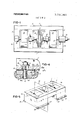
- FIG. 1 is a semi-diagrammatic plan view of a double revolving disk refiner.
- FIGS. 2 and 3 are respectively a side elevational view and a plan view of a double revolving disk refiner incorporating the base of the present invention.
- FIG. 4 is a fragmentary view, partly in cross section, illustrating the affixing of the base to the supporting foundation at one of the positions wherein the base is capable of longitudinal shifting with respect to the foundation.
- FIG. 5 is a semi-diagrammatic perspective view illustrating the two points at which the base is fixedly secured to the foundation and the common plane extending transversely of the base and through the two fixed points.
- FIG. 1 is a semi-diagrammatic plan view illustrating the basic elements of a double revolving disk refiner.
- the base is generally indicated by the index numeral l.
- the base comprises a pair of outboard bearing pedestals 2 and 3, a pair of inboard bearing pedestals 4 and 5 and a pair of top rails 6 and 7 (indicated in dotted lines). It will be noted that the top rails 6 and 7 join the bearing pedestals 2 through 5 at their upper corners. In prior art constructions, a pair of bottom rails (not shown) corresponding to the top rails 6 and 7 joined the bottom edges of the bearing pedestals 2 through 5.
- bottom rail segments are provided, two bottom rail segments being located at each side of the base 1.
- bottom rail segments are joined by bottom rail segments and similarly on each side the outboard bearing pedestal 2 and the inboard bearing pedestal 4 are joined by bottom rail segments.
- Two such bottom rail segments are in dotted lines at 8 and 9 in FIG. 2. It will be understood by one skilled in the art that the top rails 6 and 7 and the various bottom rail segments are not readily discernible in the finished machine because the base is provided with various end and side plates, grills, and other like appurtenances.
- FIG. 1 a pair of facing refining disks are shown at 10 and 11.
- the disk 10 bears a refining surface 12 and the disk 11 carries a refining surface 13.
- the disks 10 and 1 l are normally surrounded by a housing.
- the housing has been eliminated in'FIG. 1.
- the housing is shown in FIGS. 2 and 3 at 14.
- the housing 14 has an inlet means 15 for pulp to be refined and outlet means 16 for the refined pulp. It will be evident from FIGS. 1 through 3 that the disks 10 and 11, their respective refining surfaces 12 and 13 and the surrounding housing 14 are located between the inboard bearing pedestals 4 and 5.
- the disk 10 is supported at the end of a shaft 17 which passes through appropriate sealing means in the housing 14.
- the shaft 17 is, in turn, supported in an inboard bearing 18 mounted on the inboard bearing pedestal 5 and an outboard bearing 19 mounted on the outboard bearing pedestal 3.
- a motor means 20 drives the shaft 17 in the direction of arrow A and is supported on the base between inboard bearing pedestal 5 and outboard bearing pedestal 3.
- the disk 11 is mounted at the end of a shaft 21 which also passes through a suitable seal in the housing 14.
- the shaft 21 is supported by an inboard bearing 22 mounted on the inboard bearing pedestal 4 and an outboard bearing 23 mounted on the outboard bearing pedestal 2.
- the shaft 21 is rotated in the direction of arrow B by motor means 24.
- the motor means 24 is supported by the base between inboard bearing pedestal 4 and outboard bearing pedestal 2. It will be noted from arrows A and B that the disks 10 and 11 and their respective refining surfaces 12 and 13 are rotated in opposite directions.
- the shaft 21 may be axially shiftable in the bearings 22 and 23 so that the distance between refining surfaces 12 and 13 may be accurately regulated.
- Means to shift the shaft 21 may take the form of a cylinder 25 or other device which is actuated in response to some form of control system (not shown).
- the end 1a of the base 1 is frequently referred to as the control end.
- the inlet 15 (FIG. 2) feeds pulp to be refined into the housing 14 from the opposite end of the base, the base end 1b is frequently referred to as the feed" end.
- FIGS. 2 and 3 the refiner, incorporating the base of the present invention, is shown in its entirety (except for various control panels and the like).
- like parts have been given the same index numerals as were used in FIG. 1.
- the motor 24 and part at least of the bearing means 22 and 23 are provided with a cover member generally indicated at 26.
- the motor 20 and portions at least of bearings 18 and 19 are provided with a cover means generally indicated at 27.
- the base 1 is provided along its side edges with mounting flanges 28 and 29 extending between the outboard bearing pedestal 2 and the inboard bearing pedestal 4.
- additional mounting flanges 30 and 31 extend between outboard bearing pedestal 3 and inboard bearing pedestal 5.
- Each mounting flange 28 through 31 is affixed to the base in any suitable manner and each may be provided with additional bracing means 23a through 311a, respectively.
- the mounting flange 23 has a pair of perforations 32 and 33 therein.
- the mounting flange 29 has perforations 34 and 35;
- the mounting flange 30 has perforations 36 and 37; while the mounting flange 311 has perforations 33 and 39.
- FIG. is a semi-diagrammatic perspective view illustrating the base member of FIGS. ll through 3 and like parts have again been given like index numerals.
- the diametrically opposed perforations 37 and 39 lie in a plane (indicated in dotted line at 40) which extends transversely of the base i and is perpendicular to the long axis of the base I.
- the plane 40 is also indicated in FIGS. 2 and 3.
- FIG. 4 is a fragmentary cross sectional view wherein a portion of the supporting foundation is indicated at 41.
- the mounting flange shown in FIG. 4 can be considered to be any of the mounting flanges 23 through 311 and the perforation shown therein may be considered to be any of the perforations 32 through 36 and 38.
- the flange shown in FIG. 4 shall be considered to be flange 29 and the perforation 34 therein shall be considered to be elon' gated.
- the supporting foundation will usually be provided with sole plates.
- One such sole plate is shown at 42 in FIG. 4. A portion of the sole plate will extend below the top surface of the foundation 41 and the sole plate will be affixed to the foundation by any suitable means such as anchor bolts or the like (not shown).
- FIG. 4 illustrates an exemplary assembly.
- the sole plate 42 is illustrated as having a bore or perforation 43.
- a pipe or sleeve 44 extend through the perforation 43 and is embedded in the foundation 41.
- the pipe 44 surrounds the fastening bolt 45.
- the annular space between the bolt 45 and sleeve 44 is filled with a suitable resilient sealing material 44a.
- the bolt 45 extends through the elongated perforation 34 and receives a washer 46 and nut 47.
- a shim of nylon, Teflon or other suitable material may be located between the sole plate 42 and the mounting flange 29.
- a shim 48 is illustrated having upper and lower layers 48a and 43b of stainless steel and an 40 extending transversely of the base 11 and perpendicular to the long axis of the base.
- the perforations 37 and 39 define two diametrically opposed points at which the base i is fixedly secured to the foundation 41. At all other points where the base I is affixed to the foundation (i.e., at perforations 32 through 36 and 38) the base is capable of longitudinal shifting with respect to the foundation.
- the base ll of the present invention has split bottom rails, rather than continuous bottom rails extending between inboard bearing pedestals 4 and 5, the top rails are free to expand and elongate in an axial sense without restriction by the bottom rail segments. Furthermore, the base 1, including the top rails 6 and 7 and the bottom rail segments, is free to expand away from. the plane 40 passing through the hold-down bolts in perforations 37 and 39. In this way, the tendency of the top rails 6 and 7 to bow upwardly is substantially eliminated.
- the invention structure provides a base wherein end spaced base segments are interconnected only in an area of the upper portions of their most adjacent end surfaces to define an opening forming a refiner well.
- the perforations 3'7 and 39 could be elongated and the perforations 32 and 34 could be circular. Under these circumstances, the perforations 32 and 34 would define the two points at which the base it is fixedly mounted to the supporting foundation 411. Furthermore, it is within the scope of the present inventon to make the top rails 6 and 7, the bottom rail segments and the bearing pedestals 2 through 5 of hollow construction so that fluid could be circulated therethrough for additional thermal stability.
- the invention in any case establishes and maintains substantially level the refiner base segments and the interconnecting upper rail structure. This in turn establishes and generally maintains the desired relation of the opposed refining surfaces under the extreme conditions of temperature and pressure to which they are subjected in use.
- a refiner support structure including a base comprised of end spaced base segments arranged to seat to a supporting foundation and means interconnecting said segments in an area limited to upper portions of their most adjacent end surfaces, said end spaced segments and said interconnecting means defining a well accommodating opposed refiner means at least one of which rotates relative the other and said base segments having means for anchoring thereof to the supporting foundation in a plane generally transverse to the longitudinal axis thereof and further means to provide for connection thereof to the supporting foundation in a manner to accommodate axial elongation and displacement of said base segments relative to said plane whereby to generally maintain the level of said base segments.
- a refiner support structure as in claim 1 characterized by each of said base segments defining bearing support structure for orienting the supported refiner means in a predetermined opposed relation and the arrangement and construction of said base segments providing means tending to maintain the predetermined opposed relation of said refiner means.
- a refiner support structure as in claim 1 characterized by said base segments having a pair of laterally spaced rail structures forming said interconnecting means which are positioned to their outer sides and adjacent their upper ends to establish the upper level of said base segments in a desired plane of reference and said base segments being otherwise free of and relatively displaced from each other.
- a refiner support structure as in claim 1 characterized by said base segments having additional anchoring means adjacent the bottom thereof formed to provide for a guided restraint of said base segments inhibiting vertical displacement thereof from the supporting foundation.
- each of said base segments includes an inboard and an outboard pedestal in substantially parallel spaced relation and said segments are joined by top rails providing said interconnecting means, said outboard pedestals being located at the remote ends of said segments and said inboard pedestals being included in adjacent end portions of said segments, said inboard and outboard pedestals providing thereon means for accommodating in a bearing relation thereto shaft means mounting the opposed refiner means.
- a refiner support structure as in claim 5 characterized by said end spaced base segments being interconnected by rail members at upper corners thereof and the inboard and outboard pedestals in each said base segment being interconnected by further rail members at their lower corners.
- each of said base segments having means defining mounting flanges on opposite sides thereof adapted to rest on ground surface, portions of said mounting flanges to respectively opposite sides thereof having a formation affording said means for anchoring of the connected base segment to the supporting foundation in a fixed relation thereto and other portions of said mounting flanges having symmetrically arranged elongate openings accommodating attaching means for said base segments and the relative movement of said base segments to the extent accommodated by the elongation of said openings.
- a refiner support structure as in claim 1 characterized by means provided in underlying relation to portions of said base segments to facilitate a smooth axial elongation and displacement of said base segments relative to said plane.
- a refiner support structure as in claim 1 characterized by at least one said base segment including an inboard and an outboard pedestal in substantially parallel spaced relation and said segments being joined at their adjacent upper comers by rail members forming said interconnecting means and said anchoring means being located in a plane common to said inboard pedestal.
- a refiner support structure as in claim 9 characterized by each of said base segments being provided at opposite sides of their bottoms with flange means a portion of which includes apertures for applying bolts therethrough to afford said anchoring means and said flange means including elongate slots for receiving therethrough hold down means which provides, within the limits of said slots, an axial shifting or elongation of said base segments.
- Refiner support structure as in claim 10 characterized by bearing means disposing in underlying supporting relation to the flange means including said elongate openings.
- a refiner support structure including a base comprised of pairs of inboard and outboard pedestals, top rail means commonly joining all said pedestals at upper edges thereof, and bottom rail means joining each outboard pedestal to an adjacent inboard pedestal but being discontinuous with respect to adjacent inboard pedestals to obviate bowing of the base due to differential response of said top and bottom rail means to applied thermal loads.
- a refiner support structure characterized by means for mounting said base to a supporting foundation to apply a guided restraint to longitudinal elongation of said base under thermal expansion.
Landscapes
- Paper (AREA)
Abstract
A base for a pulp refiner of the type wherein the refining surfaces are supported at substantially the longitudinal axial center of the base. The base comprises a pair of end members the facing portions of which are in parallel spaced relationship with the refining surfaces supported therebetween. The end members are joined by a pair of rails in parallel spaced relationship and affixed to the end members along their upper longitudinal edges. Means are provided for mounting the refiner base on a supporting foundation. The mounting means are such that one of the end members of the base is fixedly secured to the foundation at two points lying in a plane extending transversely of that end member and the refiner base. The remainder of the refiner base is capable of longitudinal shifting with respect to the foundation toward and away from the above mentioned plane when subjected to thermal contraction and expansion due to heat generated by the refining operation, whereby to prevent bowing and distortion of the refiner base and to maintain parallelism of the refining surfaces.
Description
Uni ttes Sheen et al.
[ RlEl lNlER EASE [73] Assignee: The Bauer Bros. Co., Springfield,
Ohio
[22] Filed: May 24-, 11972 [21] Appl. No.: 256,548
[52] 11.8. C1 281/251, 241/286, 248/19 [51] lnt. C1. B2 11) 41/02, 302C 7/14 [58] Field 011 Search 241/285 R, 285 A, 244,
[56] References Cited UNITED STATES PATENTS 1,111,274 9/1914 Sorensen 241/251 1,738,288 12/1929 Eppenbach.... 241/251 2,568,783 9/1951 Woodruff 241/285 R 3,166,260 1/1965 Steiniger et a1 241/285 R 3,589,629 6/1971 Michel et a1 241/251 3,369,783 2/1968 Keating 248/19 3,589.62) 6/1971 Michel 241/251 Primary Examiner-Granville Y. Custer, Jr. Assistant Examinerlloward N. Goldberg flttorney, Agent, or FirmJerome 1?. Bloom 7 [5 7] ABSTRACT A base for a pulp refiner of the type wherein the refining surfaces are supported at substantially the longitudinal axial center of the base. The base comprises a pair of end members the facing portions of which are in parallel spaced relationship with the refining surfaces supported therebetween. The end members are joined by a pair of rails in parallel spaced relationship and affixed to the end members along their upper longitudinal edges. Means are provided for mounting the refiner base on a supporting foundation. The mounting means are such that one of the end members of the base is fixedly secured to the foundation at two points lying in a plane extending transversely of that end member and the refiner base. The remainder of the refiner base is capable of longitudinal shifting with respect to the foundation toward and away from the above mentioned plane when subjected to thermal contraction and expansion due to heat generated by the refining operation, whereby to prevent bowing and distortion of the refiner base and to maintain parallelism of the refining surfaces. 1
13 Claims, 5 Drawing Figures marinas sass BACKGROUND OF THE INVENTION 1. Field of the Invention The invention relates to a refiner base, and more particularly to a refiner base free of longitudinal bowing and distortion when subjected to thermal expansion by virtue of the heat generated in the general area of the refining surfaces during the refining operation.
2. Description of the Prior Art While not intended to be so limited, for purposes of an exemplary showing the refiner base of the present invention will be described with respect to its application as a base for a double revolving disk pulp refiner, as is well known in the art.
In general, a double revolving disk refiner comprises a pair of disks in parallel facing relationship. The refining surfaces are affixed to the facing surfaces of the disks. The pulp to be refined is caused to pass between the refining surfaces.
The disks and their respective refining surfaces are enclosed in a housing having inlet means for the pulp to be refined and outlet means for the refined pulp. Each disk is mounted on the end of a shaft passing through the housing. The disk shafts are coaxial and extend in opposite directions. Each shaft is provided with a motor means to rotate the shaft and typically the shafts are rotated in opposite directions.
A base means, mounted on an appropriate foundation, is provided to support the shafts, their respective motors, disks and refining surfaces, together with the housing about the disks and other appurtenances of the refiner. Heretofore, prior art base structures have generally comprised a series of four bearing pedestals in parallel spaced relationship and extending transversely of the base. The bearing pedestals have been joined at their upper corners by a pair of top rails extending longitudinally of the base and at their lower corners by a pair of bottom rails extending longitudinally of the base. The bearing pedestals located at the ends of the base have generally been termed the outboard bearing pedestals and the intermediate bearing pedestals have usually been termed the inboard bearing pedestals. The disks, carrying the refining surfaces, and the disk housing were located between the inboard bearing pedestals. Each shaft was supported in hearings on one of the inboard bearing pedestals and the adjacent one of the outboard bearing pedestals. The motor for each shaft was located between the inboard and outboard bearing pedestals upon which that shaft was mounted. Finally, the refiner base was affixed to its supporting foundation by hold-down bolts or the like.
In the refining operation, heat is developed by friction, etc., and is concentrated in the general area of the refining surfaces. Thus, in the double revolving disk refiner used as an exemplary embodiment herein, the heat is concentrated at the axial center of the base between the inboard pedestals and to a greater extent at the top rails of the refiner base than at its bottom rails.
Heretofore, the refiner base has tended to become distorted from uneven thermal expansion. This is true because the inboard bearing pedestals have tended to expand more than the outboard bearing pedestals and the top rails have tended to expand more than the bottom rails.
Since both top rails have tended to have the same temperature at operating equilibrium (the same being true of both bottom rails), thermal expansions across the base have not been a significant problem, but longitudinal thermal expansions have been. This was true because as the top rails grew longitudinally more than the bottom rails, they have tended to bow upwardly in the middle. At times, the upward bowing of the top rails has resulted in sufi'icient force on the hold-down bolts affixing the refiner base to the foundation to cause the bolts to fail.
The upward bowing of the top rails and the greater expansion of the inboard bearing pedestals (as compared to the outboard bearing pedestals) has resulted in a greater upward shift of the inboard shaft bearings than the outboard shaft bearings. Thus, while the refiner shafts were coaxial at the outset, they would lose their coaxial relationship during the refining operation by virtue of the operating temperature differentials. This, in turn, would directly affect the parallelism of the refining surfaces and the quality of the refined pulp product.
Prior art workers found that it was impractical to attempt to build distortions into the refining machine such that under operating conditions the refiner shafts would achieve a coaxial relationship. This is true because the operating temperature differentials and the resulting bowing of the base cannot accurately be predicted.
As a result, prior art workers: have attempted to equalize the temperatures throughout the base by providing bearing pedestals and top and bottom rails of hollow construction with fluid circulating throughout these members. While this was partially effective, it was not sufficient to equalize the temperature of the top and bottom rails and bowing and distortion still occurred.
The present invention is directed to a refiner base having inboard and outboard pedestals and top rails. However, the bottom longitudinal edges of the base are not provided with continuous bottom rails. Adjacent inboard and outboard bearing pedestals may be joined by bottom rail segments but the inboard pedestals, themselves, are not joined at their bottoms. Furthermore, the base of the present invention is fixedly secured to the supporting foundation at only two points. These points lie on either side of the base and in a plane extending transversely of the long axis of the base. At all other points where it is affixed to the foundation, the base is capable of longitudinal shifting with respect to the foundation.
As a consequence, the top rails are free to expand without restriction from the bottom rail segments. The bottom rail segments are free to expand away from the above mentioned two fixed points. Thus, the tendency of the top rails to bow is eliminated. This, in turn, en ables the parallelism of the refining surfaces to be maintained. It will be understood that, as was the case with prior art refiner bases, thermal expansion transversely of the base does not offer a severe problem.
SUMMARY OF THE INVENTION The refiner base of the present invention comprises a pair of inboard and a pair of outboard bearing pedestals. The bearing pedestals are joined by a pair of longitudinally extending top rails. On each side of the refiner base adjacent inboard and outboard bearing pedestals may be joined by bottom rail segments, but the inboard bearing pedestals are not so joined.
In a preferred embodiment of the invention, on each side of the refiner base there is a pair of horizontally oriented mounting flanges. Each mounting flange ex- I tends between one of the outboard bearing pedestals and the adjacent one of the inboard bearing pedestals. The corresponding flanges on either side of the base have diametrically opposed pairs of holes therein by which the base may be affixed to an appropriate supporting foundation by hold-down bolts or the like. One pair of diametrically opposed flange holes are so sized that the hold-down bolts extending therethrough fixedly secure the base to the foundation at the positions of these two holes. These holes lie in a plane extending transversely of the long axis of the base.
The remaining flange holes are elongated whereby at the positions of these holes the base is free to shift longitudinally with respect to the foundation. Thus, when subjected to thermal expansion and contraction, the entire base structure may shift toward and away from the two fixed points described above. This, in conjunction with the absence of bottom rails between the inboard bearing pedestals, greatly minimizes or eliminates bowing of the top rails and greatly enhances the maintaining of parallelism between the refining surfaces.
BRIEF DESCRIPTION OF THE DRAWINGS FIG. 1 is a semi-diagrammatic plan view of a double revolving disk refiner.
FIGS. 2 and 3 are respectively a side elevational view and a plan view of a double revolving disk refiner incorporating the base of the present invention.
FIG. 4 is a fragmentary view, partly in cross section, illustrating the affixing of the base to the supporting foundation at one of the positions wherein the base is capable of longitudinal shifting with respect to the foundation.
FIG. 5 is a semi-diagrammatic perspective view illustrating the two points at which the base is fixedly secured to the foundation and the common plane extending transversely of the base and through the two fixed points.
DESCRIPTION OF THE PREFERRED EMBODIMENTS FIG. 1 is a semi-diagrammatic plan view illustrating the basic elements of a double revolving disk refiner. In FIG. 1 the base is generally indicated by the index numeral l. The base comprises a pair of outboard bearing pedestals 2 and 3, a pair of inboard bearing pedestals 4 and 5 and a pair of top rails 6 and 7 (indicated in dotted lines). It will be noted that the top rails 6 and 7 join the bearing pedestals 2 through 5 at their upper corners. In prior art constructions, a pair of bottom rails (not shown) corresponding to the top rails 6 and 7 joined the bottom edges of the bearing pedestals 2 through 5. In accordance with the present invention, bottom rail segments are provided, two bottom rail segments being located at each side of the base 1. Thus, on either side the outboard bearing pedestal 3 and the inboard pedestal 5 are joined by bottom rail segments and similarly on each side the outboard bearing pedestal 2 and the inboard bearing pedestal 4 are joined by bottom rail segments. Two such bottom rail segments are in dotted lines at 8 and 9 in FIG. 2. It will be understood by one skilled in the art that the top rails 6 and 7 and the various bottom rail segments are not readily discernible in the finished machine because the base is provided with various end and side plates, grills, and other like appurtenances.
In FIG. 1 a pair of facing refining disks are shown at 10 and 11. The disk 10 bears a refining surface 12 and the disk 11 carries a refining surface 13.
It will be noted that the disks 10 and 1 l are normally surrounded by a housing. For purposes of clarity, the housing has been eliminated in'FIG. 1. However, the housing is shown in FIGS. 2 and 3 at 14. The housing 14 has an inlet means 15 for pulp to be refined and outlet means 16 for the refined pulp. It will be evident from FIGS. 1 through 3 that the disks 10 and 11, their respective refining surfaces 12 and 13 and the surrounding housing 14 are located between the inboard bearing pedestals 4 and 5.
The disk 10 is supported at the end of a shaft 17 which passes through appropriate sealing means in the housing 14. The shaft 17 is, in turn, supported in an inboard bearing 18 mounted on the inboard bearing pedestal 5 and an outboard bearing 19 mounted on the outboard bearing pedestal 3. A motor means 20 drives the shaft 17 in the direction of arrow A and is supported on the base between inboard bearing pedestal 5 and outboard bearing pedestal 3.
Similarly, the disk 11 is mounted at the end of a shaft 21 which also passes through a suitable seal in the housing 14. The shaft 21 is supported by an inboard bearing 22 mounted on the inboard bearing pedestal 4 and an outboard bearing 23 mounted on the outboard bearing pedestal 2. The shaft 21 is rotated in the direction of arrow B by motor means 24. The motor means 24 is supported by the base between inboard bearing pedestal 4 and outboard bearing pedestal 2. It will be noted from arrows A and B that the disks 10 and 11 and their respective refining surfaces 12 and 13 are rotated in opposite directions.
Finally, the shaft 21 may be axially shiftable in the bearings 22 and 23 so that the distance between refining surfaces 12 and 13 may be accurately regulated. Means to shift the shaft 21 may take the form of a cylinder 25 or other device which is actuated in response to some form of control system (not shown). As a consequence, the end 1a of the base 1 is frequently referred to as the control end. Since the inlet 15 (FIG. 2) feeds pulp to be refined into the housing 14 from the opposite end of the base, the base end 1b is frequently referred to as the feed" end.
In FIGS. 2 and 3, the refiner, incorporating the base of the present invention, is shown in its entirety (except for various control panels and the like). In FIGS. 2 and 3, like parts have been given the same index numerals as were used in FIG. 1. It wil be noted that the motor 24 and part at least of the bearing means 22 and 23 are provided with a cover member generally indicated at 26. Similarly, the motor 20 and portions at least of bearings 18 and 19 are provided with a cover means generally indicated at 27.
At its bottom, the base 1 is provided along its side edges with mounting flanges 28 and 29 extending between the outboard bearing pedestal 2 and the inboard bearing pedestal 4. Similarly, additional mounting flanges 30 and 31 extend between outboard bearing pedestal 3 and inboard bearing pedestal 5. Each mounting flange 28 through 31 is affixed to the base in any suitable manner and each may be provided with additional bracing means 23a through 311a, respectively.
The mounting flange 23 has a pair of perforations 32 and 33 therein. Similarly, the mounting flange 29 has perforations 34 and 35; the mounting flange 30 has perforations 36 and 37; while the mounting flange 311 has perforations 33 and 39.
It will be noted that the diametrically opposed pairs of perforations 33-35, 32-34 and 36-38 are elongated in configuration. On the other hand, the diametrically opposed pair of perforations 37-39 are of circular configuration. FIG. is a semi-diagrammatic perspective view illustrating the base member of FIGS. ll through 3 and like parts have again been given like index numerals. As is clearly shown in FIG. 5, the diametrically opposed perforations 37 and 39 lie in a plane (indicated in dotted line at 40) which extends transversely of the base i and is perpendicular to the long axis of the base I. The plane 40 is also indicated in FIGS. 2 and 3. The reason for the perforations 37 and 39 being circular rather than elongated will be described hereinaf- The base ll will be mounted on a suitable supporting foundation. FIG. 4 is a fragmentary cross sectional view wherein a portion of the supporting foundation is indicated at 41. The mounting flange shown in FIG. 4 can be considered to be any of the mounting flanges 23 through 311 and the perforation shown therein may be considered to be any of the perforations 32 through 36 and 38. For purposes of explanation the flange shown in FIG. 4 shall be considered to be flange 29 and the perforation 34 therein shall be considered to be elon' gated.
At the positions of all of the perforations in the machine mounting flanges, the supporting foundation will usually be provided with sole plates. One such sole plate is shown at 42 in FIG. 4. A portion of the sole plate will extend below the top surface of the foundation 41 and the sole plate will be affixed to the foundation by any suitable means such as anchor bolts or the like (not shown).
At the position of each of the perforations in the base mounting flanges, the foundation will have an anchor bolt, .l-bolt or other suitable fastening means embedded therein. The precise nature of the fastening means and the manner in which it is affixed in the foundation does not constitute a limitation on the present invention. FIG. 4 illustrates an exemplary assembly. In FIG. 4 the sole plate 42 is illustrated as having a bore or perforation 43. A pipe or sleeve 44 extend through the perforation 43 and is embedded in the foundation 41. The pipe 44 surrounds the fastening bolt 45. The annular space between the bolt 45 and sleeve 44 is filled with a suitable resilient sealing material 44a.
The bolt 45 extends through the elongated perforation 34 and receives a washer 46 and nut 47.
While it will be evident that with this arrangement the base 1 will be securely held to the sole plate 42 and foundation 411, the base will nevertheless be free to shift in the directions of arrows C and D by virture of the elongated configuration of perforation 34. To facilitate this shifting action, a shim of nylon, Teflon or other suitable material may be located between the sole plate 42 and the mounting flange 29. For purposes of an examplary showing, a shim 48 is illustrated having upper and lower layers 48a and 43b of stainless steel and an 40 extending transversely of the base 11 and perpendicular to the long axis of the base. The perforations 37 and 39 define two diametrically opposed points at which the base i is fixedly secured to the foundation 41. At all other points where the base I is affixed to the foundation (i.e., at perforations 32 through 36 and 38) the base is capable of longitudinal shifting with respect to the foundation.
Thus, during operation, when heat is generated primarily at the location of the refining surfaces 12 and 13 (i.e., primarily in the area between inboard bearing pedestals 4 and 5) thermal expansion or elongation of the top rails 6 and 7 will occur. Since the base ll of the present invention has split bottom rails, rather than continuous bottom rails extending between inboard bearing pedestals 4 and 5, the top rails are free to expand and elongate in an axial sense without restriction by the bottom rail segments. Furthermore, the base 1, including the top rails 6 and 7 and the bottom rail segments, is free to expand away from. the plane 40 passing through the hold-down bolts in perforations 37 and 39. In this way, the tendency of the top rails 6 and 7 to bow upwardly is substantially eliminated.
As above seen, by way of the example illustrated, the invention structure provides a base wherein end spaced base segments are interconnected only in an area of the upper portions of their most adjacent end surfaces to define an opening forming a refiner well. By virtue of the connection of the base segments in an area limited to the upper portions thereof and their lower portions being relatively free, and by virtue: of the fixing of only one base segment to ground surface in a single plane generally transverse to the longitudinal axis of the entire refiner base, the construction described enables the one base segment to elongate in an axial sense from the described reference plane while the other base segment may axially shift with the axial elongation induced by heat in the interconnecting means. Of course, with cooling, the invention enables the refiner base to return towards its original configuration. The simplicity and benefits of the base structure as described will be readily apparent to and comprehended by those versed in the refining art.
Tests have shown that in a double revolving disk refiner provided with the base of the present invention, incidence of significant deviation of the shafts l7 and Zll from their coaxial condition (and thus deviation of the plates l0 and ill from parallelism) due to thermal expansion of the base has been substantially eliminated.
Modifications may be made in the invention without departing from the spirit of it. For example, the perforations 3'7 and 39 could be elongated and the perforations 32 and 34 could be circular. Under these circumstances, the perforations 32 and 34 would define the two points at which the base it is fixedly mounted to the supporting foundation 411. Furthermore, it is within the scope of the present inventon to make the top rails 6 and 7, the bottom rail segments and the bearing pedestals 2 through 5 of hollow construction so that fluid could be circulated therethrough for additional thermal stability.
The invention in any case establishes and maintains substantially level the refiner base segments and the interconnecting upper rail structure. This in turn establishes and generally maintains the desired relation of the opposed refining surfaces under the extreme conditions of temperature and pressure to which they are subjected in use.
From the above description it will be apparent that there is thus provided a device of the character described possessing the particular features of advantage before enumerated as desirable, but which obviously is susceptible of modification in its form, proportions, detail construction and arrangement of parts Without departing from the principle involved or sacrificing any of its advantages.
While in order to comply with the statute the invention has been described in language more or less specific as to structural features, it is to be understood that the invention is not limited to the specific features shown, but that the means and construction herein disclosed comprise but one of several modes of putting the invention into effect and the invention is therefore claimed in any of its forms or modifications within the legitimate and valid scope of the appended claims.
Having thus described our invention, we claim:
1. A refiner support structure including a base comprised of end spaced base segments arranged to seat to a supporting foundation and means interconnecting said segments in an area limited to upper portions of their most adjacent end surfaces, said end spaced segments and said interconnecting means defining a well accommodating opposed refiner means at least one of which rotates relative the other and said base segments having means for anchoring thereof to the supporting foundation in a plane generally transverse to the longitudinal axis thereof and further means to provide for connection thereof to the supporting foundation in a manner to accommodate axial elongation and displacement of said base segments relative to said plane whereby to generally maintain the level of said base segments.
2. A refiner support structure as in claim 1 characterized by each of said base segments defining bearing support structure for orienting the supported refiner means in a predetermined opposed relation and the arrangement and construction of said base segments providing means tending to maintain the predetermined opposed relation of said refiner means.
3. A refiner support structure as in claim 1 characterized by said base segments having a pair of laterally spaced rail structures forming said interconnecting means which are positioned to their outer sides and adjacent their upper ends to establish the upper level of said base segments in a desired plane of reference and said base segments being otherwise free of and relatively displaced from each other.
4. A refiner support structure as in claim 1 characterized by said base segments having additional anchoring means adjacent the bottom thereof formed to provide for a guided restraint of said base segments inhibiting vertical displacement thereof from the supporting foundation.
5. A refiner support structure as in claim 1 wherein each of said base segments includes an inboard and an outboard pedestal in substantially parallel spaced relation and said segments are joined by top rails providing said interconnecting means, said outboard pedestals being located at the remote ends of said segments and said inboard pedestals being included in adjacent end portions of said segments, said inboard and outboard pedestals providing thereon means for accommodating in a bearing relation thereto shaft means mounting the opposed refiner means.
6. A refiner support structure as in claim 5 characterized by said end spaced base segments being interconnected by rail members at upper corners thereof and the inboard and outboard pedestals in each said base segment being interconnected by further rail members at their lower corners.
7. A refiner support structure as in claim 1 characterized by each of said base segments having means defining mounting flanges on opposite sides thereof adapted to rest on ground surface, portions of said mounting flanges to respectively opposite sides thereof having a formation affording said means for anchoring of the connected base segment to the supporting foundation in a fixed relation thereto and other portions of said mounting flanges having symmetrically arranged elongate openings accommodating attaching means for said base segments and the relative movement of said base segments to the extent accommodated by the elongation of said openings.
8. A refiner support structure as in claim 1 characterized by means provided in underlying relation to portions of said base segments to facilitate a smooth axial elongation and displacement of said base segments relative to said plane.
9. A refiner support structure as in claim 1 characterized by at least one said base segment including an inboard and an outboard pedestal in substantially parallel spaced relation and said segments being joined at their adjacent upper comers by rail members forming said interconnecting means and said anchoring means being located in a plane common to said inboard pedestal.
10. A refiner support structure as in claim 9 characterized by each of said base segments being provided at opposite sides of their bottoms with flange means a portion of which includes apertures for applying bolts therethrough to afford said anchoring means and said flange means including elongate slots for receiving therethrough hold down means which provides, within the limits of said slots, an axial shifting or elongation of said base segments.
11. Refiner support structure as in claim 10 characterized by bearing means disposing in underlying supporting relation to the flange means including said elongate openings.
12. A refiner support structure including a base comprised of pairs of inboard and outboard pedestals, top rail means commonly joining all said pedestals at upper edges thereof, and bottom rail means joining each outboard pedestal to an adjacent inboard pedestal but being discontinuous with respect to adjacent inboard pedestals to obviate bowing of the base due to differential response of said top and bottom rail means to applied thermal loads.
13. A refiner support structure according to claim 12, characterized by means for mounting said base to a supporting foundation to apply a guided restraint to longitudinal elongation of said base under thermal expansion.
k =l= k
Claims (13)
1. A refiner support structure including a base comprised of end spaced base segments arranged to seat to a supporting foundation and means interconnecting said segments in an area limited to upper portions of their most adjacent end surfaces, said end sPaced segments and said interconnecting means defining a well accommodating opposed refiner means at least one of which rotates relative the other and said base segments having means for anchoring thereof to the supporting foundation in a plane generally transverse to the longitudinal axis thereof and further means to provide for connection thereof to the supporting foundation in a manner to accommodate axial elongation and displacement of said base segments relative to said plane whereby to generally maintain the level of said base segments.
2. A refiner support structure as in claim 1 characterized by each of said base segments defining bearing support structure for orienting the supported refiner means in a predetermined opposed relation and the arrangement and construction of said base segments providing means tending to maintain the predetermined opposed relation of said refiner means.
3. A refiner support structure as in claim 1 characterized by said base segments having a pair of laterally spaced rail structures forming said interconnecting means which are positioned to their outer sides and adjacent their upper ends to establish the upper level of said base segments in a desired plane of reference and said base segments being otherwise free of and relatively displaced from each other.
4. A refiner support structure as in claim 1 characterized by said base segments having additional anchoring means adjacent the bottom thereof formed to provide for a guided restraint of said base segments inhibiting vertical displacement thereof from the supporting foundation.
5. A refiner support structure as in claim 1 wherein each of said base segments includes an inboard and an outboard pedestal in substantially parallel spaced relation and said segments are joined by top rails providing said interconnecting means, said outboard pedestals being located at the remote ends of said segments and said inboard pedestals being included in adjacent end portions of said segments, said inboard and outboard pedestals providing thereon means for accommodating in a bearing relation thereto shaft means mounting the opposed refiner means.
6. A refiner support structure as in claim 5 characterized by said end spaced base segments being interconnected by rail members at upper corners thereof and the inboard and outboard pedestals in each said base segment being interconnected by further rail members at their lower corners.
7. A refiner support structure as in claim 1 characterized by each of said base segments having means defining mounting flanges on opposite sides thereof adapted to rest on ground surface, portions of said mounting flanges to respectively opposite sides thereof having a formation affording said means for anchoring of the connected base segment to the supporting foundation in a fixed relation thereto and other portions of said mounting flanges having symmetrically arranged elongate openings accommodating attaching means for said base segments and the relative movement of said base segments to the extent accommodated by the elongation of said openings.
8. A refiner support structure as in claim 1 characterized by means provided in underlying relation to portions of said base segments to facilitate a smooth axial elongation and displacement of said base segments relative to said plane.
9. A refiner support structure as in claim 1 characterized by at least one said base segment including an inboard and an outboard pedestal in substantially parallel spaced relation and said segments being joined at their adjacent upper corners by rail members forming said interconnecting means and said anchoring means being located in a plane common to said inboard pedestal.
10. A refiner support structure as in claim 9 characterized by each of said base segments being provided at opposite sides of their bottoms with flange means a portion of which includes apertures for applying bolts therethrough to afford said anchoring means and said flange means including elongate slots for reCeiving therethrough hold down means which provides, within the limits of said slots, an axial shifting or elongation of said base segments.
11. Refiner support structure as in claim 10 characterized by bearing means disposing in underlying supporting relation to the flange means including said elongate openings.
12. A refiner support structure including a base comprised of pairs of inboard and outboard pedestals, top rail means commonly joining all said pedestals at upper edges thereof, and bottom rail means joining each outboard pedestal to an adjacent inboard pedestal but being discontinuous with respect to adjacent inboard pedestals to obviate bowing of the base due to differential response of said top and bottom rail means to applied thermal loads.
13. A refiner support structure according to claim 12, characterized by means for mounting said base to a supporting foundation to apply a guided restraint to longitudinal elongation of said base under thermal expansion.
Priority Applications (2)
| Application Number | Priority Date | Filing Date | Title |
|---|---|---|---|
| US00256548A US3799461A (en) | 1972-05-24 | 1972-05-24 | Refiner base |
| CA170,229A CA983906A (en) | 1972-05-24 | 1973-05-02 | Refiner base |
Applications Claiming Priority (1)
| Application Number | Priority Date | Filing Date | Title |
|---|---|---|---|
| US00256548A US3799461A (en) | 1972-05-24 | 1972-05-24 | Refiner base |
Publications (1)
| Publication Number | Publication Date |
|---|---|
| US3799461A true US3799461A (en) | 1974-03-26 |
Family
ID=22972648
Family Applications (1)
| Application Number | Title | Priority Date | Filing Date |
|---|---|---|---|
| US00256548A Expired - Lifetime US3799461A (en) | 1972-05-24 | 1972-05-24 | Refiner base |
Country Status (2)
| Country | Link |
|---|---|
| US (1) | US3799461A (en) |
| CA (1) | CA983906A (en) |
Cited By (4)
| Publication number | Priority date | Publication date | Assignee | Title |
|---|---|---|---|---|
| US4085914A (en) * | 1976-03-09 | 1978-04-25 | General Electric Company | Dynamoelectric machine mounting assembly |
| US4694190A (en) * | 1985-12-23 | 1987-09-15 | General Electric Company | Integral generator housing and base for a turbine generator |
| US4784364A (en) * | 1987-09-17 | 1988-11-15 | Arrow Support Systems Corp. | Heat-barrier chock and sole plate system |
| US5040767A (en) * | 1988-05-30 | 1991-08-20 | Mitsubishi Denki K.K. | Traveling stand for traveling type industrial robot device |
Citations (6)
| Publication number | Priority date | Publication date | Assignee | Title |
|---|---|---|---|---|
| US1111274A (en) * | 1911-04-07 | 1914-09-22 | Sprout Waldron & Company | Attrition-mill. |
| US1738288A (en) * | 1927-07-19 | 1929-12-03 | Us Colloid Mill Corp | Homogenizing mill |
| US2568783A (en) * | 1948-03-04 | 1951-09-25 | Bauer Bros Co | Temperature controlled mill base |
| US3166260A (en) * | 1961-02-10 | 1965-01-19 | Bauer Bros Co | Refiner base structure |
| US3369783A (en) * | 1966-02-24 | 1968-02-20 | Carrier Corp | Machine support |
| US3589629A (en) * | 1966-09-16 | 1971-06-29 | Bauer Bros Co | Refiner installation |
-
1972
- 1972-05-24 US US00256548A patent/US3799461A/en not_active Expired - Lifetime
-
1973
- 1973-05-02 CA CA170,229A patent/CA983906A/en not_active Expired
Patent Citations (6)
| Publication number | Priority date | Publication date | Assignee | Title |
|---|---|---|---|---|
| US1111274A (en) * | 1911-04-07 | 1914-09-22 | Sprout Waldron & Company | Attrition-mill. |
| US1738288A (en) * | 1927-07-19 | 1929-12-03 | Us Colloid Mill Corp | Homogenizing mill |
| US2568783A (en) * | 1948-03-04 | 1951-09-25 | Bauer Bros Co | Temperature controlled mill base |
| US3166260A (en) * | 1961-02-10 | 1965-01-19 | Bauer Bros Co | Refiner base structure |
| US3369783A (en) * | 1966-02-24 | 1968-02-20 | Carrier Corp | Machine support |
| US3589629A (en) * | 1966-09-16 | 1971-06-29 | Bauer Bros Co | Refiner installation |
Cited By (4)
| Publication number | Priority date | Publication date | Assignee | Title |
|---|---|---|---|---|
| US4085914A (en) * | 1976-03-09 | 1978-04-25 | General Electric Company | Dynamoelectric machine mounting assembly |
| US4694190A (en) * | 1985-12-23 | 1987-09-15 | General Electric Company | Integral generator housing and base for a turbine generator |
| US4784364A (en) * | 1987-09-17 | 1988-11-15 | Arrow Support Systems Corp. | Heat-barrier chock and sole plate system |
| US5040767A (en) * | 1988-05-30 | 1991-08-20 | Mitsubishi Denki K.K. | Traveling stand for traveling type industrial robot device |
Also Published As
| Publication number | Publication date |
|---|---|
| CA983906A (en) | 1976-02-17 |
Similar Documents
| Publication | Publication Date | Title |
|---|---|---|
| US4258280A (en) | Supporting structure for slow speed large diameter electrical machines | |
| US3799461A (en) | Refiner base | |
| DE1054604B (en) | Nuclear reactor | |
| DE2119113A1 (en) | Self-adjusting sealing arrangement | |
| US4954375A (en) | Vibration damping apparatus | |
| US4516284A (en) | Bridging arrangement for expansion joints in the carriageways of bridges or the like | |
| US4168101A (en) | Spring assembly for a high pressure thrust bearing | |
| US4731220A (en) | Neutron reflector | |
| US3845923A (en) | Vibration-isolating mounting for engines | |
| US5052197A (en) | Apparatus for flow-through treatment of textile material, paper or the like | |
| US3174809A (en) | Self-centering radial and thrust load air bearing | |
| US3460875A (en) | Sleeve bearing | |
| US3018144A (en) | Thrust bearing assembly | |
| US4655281A (en) | Heat exchanger incorporating a tube bundle arranged in a cylindrical bundle casing held radially inside an outer cylindrical casing | |
| DE925853C (en) | Circumferential regenerative preheater with movable cover plates | |
| US4923670A (en) | Roof reflector for a nuclear reactor | |
| US2916272A (en) | Column tray-structure | |
| EP0325189B1 (en) | Rotative drum with a bearing | |
| US1865842A (en) | Sheave assembly | |
| US4211383A (en) | Arrangement for supporting vertical-axis machine housing | |
| US2246857A (en) | Engine frame construction | |
| US2732184A (en) | Pivotally supported housing for rotary regenerators | |
| US4192717A (en) | Cover for a nuclear reactor pressure vessel | |
| US4128221A (en) | Construction of a supporting grid for pipes | |
| US2979221A (en) | Load supporting means |
Legal Events
| Date | Code | Title | Description |
|---|---|---|---|
| AS | Assignment |
Owner name: SPROUT-BAUER, INC., Free format text: MERGER;ASSIGNOR:SWM CORPORATION, MERGED INTO BAUER BROS. CO. CHANGED TO;REEL/FRAME:004810/0977 Effective date: 19871029 |