US3794271A - Self-organizing control system - Google Patents
Self-organizing control system Download PDFInfo
- Publication number
- US3794271A US3794271A US00222072A US3794271DA US3794271A US 3794271 A US3794271 A US 3794271A US 00222072 A US00222072 A US 00222072A US 3794271D A US3794271D A US 3794271DA US 3794271 A US3794271 A US 3794271A
- Authority
- US
- United States
- Prior art keywords
- control system
- self
- set forth
- phase angle
- organizing control
- Prior art date
- Legal status (The legal status is an assumption and is not a legal conclusion. Google has not performed a legal analysis and makes no representation as to the accuracy of the status listed.)
- Expired - Lifetime
Links
- 230000004044 response Effects 0.000 claims description 13
- 238000005070 sampling Methods 0.000 claims description 3
- 230000006872 improvement Effects 0.000 abstract description 6
- 238000000034 method Methods 0.000 description 20
- 238000002474 experimental method Methods 0.000 description 11
- 230000009471 action Effects 0.000 description 7
- 238000010586 diagram Methods 0.000 description 7
- 230000003247 decreasing effect Effects 0.000 description 2
- 238000012986 modification Methods 0.000 description 2
- 230000004048 modification Effects 0.000 description 2
- 230000008569 process Effects 0.000 description 2
- BMZGSMUCRXYUGB-UHFFFAOYSA-N 5-chloro-2-methylaniline;hydron;chloride Chemical compound Cl.CC1=CC=C(Cl)C=C1N BMZGSMUCRXYUGB-UHFFFAOYSA-N 0.000 description 1
- 241000288147 Meleagris gallopavo Species 0.000 description 1
- 230000003190 augmentative effect Effects 0.000 description 1
- 238000004364 calculation method Methods 0.000 description 1
- 230000001364 causal effect Effects 0.000 description 1
- 230000008859 change Effects 0.000 description 1
- 230000007423 decrease Effects 0.000 description 1
- 230000001934 delay Effects 0.000 description 1
- 230000004069 differentiation Effects 0.000 description 1
- 238000006073 displacement reaction Methods 0.000 description 1
- 230000007613 environmental effect Effects 0.000 description 1
- 230000005284 excitation Effects 0.000 description 1
- 230000033001 locomotion Effects 0.000 description 1
- RGCLLPNLLBQHPF-HJWRWDBZSA-N phosphamidon Chemical compound CCN(CC)C(=O)C(\Cl)=C(/C)OP(=O)(OC)OC RGCLLPNLLBQHPF-HJWRWDBZSA-N 0.000 description 1
- 238000005096 rolling process Methods 0.000 description 1
Images


Classifications
-
- G—PHYSICS
- G05—CONTROLLING; REGULATING
- G05D—SYSTEMS FOR CONTROLLING OR REGULATING NON-ELECTRIC VARIABLES
- G05D1/00—Control of position, course, altitude or attitude of land, water, air or space vehicles, e.g. using automatic pilots
- G05D1/10—Simultaneous control of position or course in three dimensions
- G05D1/107—Simultaneous control of position or course in three dimensions specially adapted for missiles
- G05D1/108—Simultaneous control of position or course in three dimensions specially adapted for missiles animated with a rolling movement
Definitions
- ABSTRACT This disclosure relates to improvements in selforganizing control logic configurations having particular application to automatically or remotely piloted vehicles.
- the improvements include the use of multiple-point (time-distributed) functions for control sys tem performance assessment, the use of performance assessment value-signal magnitude information to govern parameter step sizes, and means for controlling an object that is rotating with a determinable angular rate but unknown phase angle relative to a fiducial angular position of the object.
- SELF-ORGANIZING CONTROL SYSTEM improvements include: (a) the use of multiple-point (time-distributed) functions for control system performance assessments, (b) the use of performance assessment value-signal magnitudeinformation to govern parameter step sizes, and means for controlling an object that is rotating with a determinable angular rate but unknown phase angle relative to a fiducial angular position of the object, said means incorporating first means for computing the performance of the SOC in accordance with variations of control system response as appearing in a system error signal, second means for estimating the phase angle of the object in accordance with a correlation between changes in the system performance computed by said first means with changes in the estimated phase angle, and third means for generating signals that actuate the controlled object in accordance with said'estimated phase angle from said second means.
- the sampling rate of the SOC can be significantly .reduced, with consequent easing of bandwidth requirements on electroniccircuits.
- a multi-point value signal V
- the multi-point value signal is one that is calculated from a number of time-distributed samples of the system response variable(s).
- the fundamental idea in this technique is to compute an estimate, I 1 of a variable indicative of the control system response which would have existed at time t, had the system continued on the path it was following prior to the most recent control actions.
- the numerical difference between this estimate and the actual system response at time t,, denoted E,, that is measured is thereby indicative of whether these recent actions improved or worsened the behavior of the system.
- One embodiment is a quadratic formula for calculation of E n n-1 n-2 rr-3 whence number, k, of past points, each point separated from its immediate neighbors by time intervals At.
- the SOC correlation logic separates causal from extraneous trend information by integrating a plurality of Aps. Thus, random environmental factors are ignored, on the average, whereas the significant response characteristics of the plant are identified.
- the non-negative weights; w w w may be selected in accordance with the harmonic sequence (such that w l, w one-half, w l/k.
- Step 1 Compute li7,,
- j Au l V 7 7* In this Way, the magnitude of the parameter is increased (geometric growth rate) until the minimum acceptable IVI is achieved. This insures observability in the controls sense. Likewise, the parameter magnitude is decreased (geometric decay rate) if necessary to avoid excessively large This keeps the disturbances introduced by the SOC experiments from being larger than necessary.
- a controlled object is rotating at a known or measurable rate but with an unknown phase angle about a given body axis, here denoted the x or roll axis, and control of pitch and yaw motions is to be established by producing torques about orthogonal axes, y and z, respectively, which are fixed in the body perpendicular to the x axis and therefore rotate with the body.
- Automatically or remotely controlled flight vehicles may fit within this category. More generally, any system or process having an unknown phase angle that is to be identified via a self-organizing control method is amenable to the following approach.
- a Ring Counter is implemented, such that its content, d is indicative at any instant, t,,, of the current best estimate of the unknown phase angle parameter.
- This output signal is transferred to a summing device having as its other input the time integral of the known or measurable value of the angular rate (e.g., the roll rate) of the system.
- the output of this summing device constitutes the instantaneous estimate of the angular position (e.g., roll attitude) of the system, and this angular position estimate is transferred to sine and cosine computing elements to obtain time-varying waveforms having suitable actuation properties, as discussed further herein below.
- the input to the Ring Counter is an increment, Ad generated by self-organizing control logic, as discussed in detail herein below.
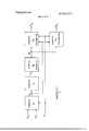
- FIG. I is a block diagram of a self-organizing controller in accordance with the present invention.
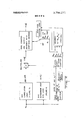
- FIG. 2 is a diagram of the interrelation among FIGS. 3 to 5, also showing the use of a Ring Counter, the content of which is the estimated phase angle of a controlled rotating object;
- FIG. 3 is the SOC Correlation Logic for determination of the polarity of experimental changes in the estimated phase angle of a controlled rotating object
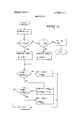
- FIG. 4 is a flow chart showing a method for computation of the SOC experiment step sizes used in estimating the phase angle of the controlled rotating object.
- FIG. 5 is a flow chart of a method for generating sinusoidally-varying and cosinusoidally-varying signals having a phase angle estimated in accordance with the invention and frequency and amplitude determined in accordance with the present invention.
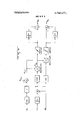
- FIG. 6 is a functional block diagram of circuitry for performing the method of FIG. 5.
- the first block implements the computation of E,,, a variable indicative of the control system response.
- E line-of-sight
- a'preferred embodiment of the function E is given by thefollowing relationship I Y E,, 0,, R ia i i... ts'gmfirr wherein A: is the timei'ni'?val between 1355553753 P* is the known or measured roll rate.
- Equation 10 provides positive semi-definite form for the quantity E,,.
- Equation 10 The method of PA discussed herein below requires such a form, but it is not necessary that the specific function of Equation 10 be implemented, and other embodiments will be apparent to those skilled in the art.
- the essential consideration is that of two time histories of E,,, that which decreases or increases more slowly is the preferred time history, the object of the improved self-organizing control system being (in this instance) to change E,- toward zero, if I possible, and in any event, to slow the rate of increase in I5, so that this variable has a smaller magnitude in the presence of the control actionsv by the SOC than it would have had otherwise.
- the third block within FIG. 1 realizes.the computation in accordance with the present invention, and the logic of this computation is shown in detail in FIGS. 2, 3, and 4.
- FIG. 2 illustrates the use of the Ring Counter in acas shown in FIG. 4. Both these logic elements receive the value signal input v, obtained in accordance with the PA method and means discussed herein above.
- Step Size Override Logic is used to increase the increment magnitude within the Ring Counter if a sequence of eight or more unsuccessful estimates have been made. .1. thi 992555 eavns s sef estim e is .1 be one in which sgn v,, 1. Furthermore, the size of step called for by the Step Size Override Logic can be made to depend upon the number of unsuccessful experiments conducted in an uninterrupted succession of such experiments. The logic for a preferred embodiment and of said override means is shown in FIG. 2.
- FIG. 3 illustrating the SOC Correlation Logic, diagrams a novel means for implementation of a weighted sum of prior step polarities employed bythe Correlation Logic.
- the specific numerical weights shown are those of a preferred but not necessary embodiment.
- the weights are applied to binary output of a tapped shift register, and the weighted sum is multiplied by sgn v,, to obtain the probability bias signal, x,,, that is, in turn used in the way disclosed by Roger L. Barron in US. Pat. No. 3,460,096 (Self-Organizing Control System).
- FIG. 4 is a logic flow chart presented in accordance with the present invention to diagram a novel method for selection of SOC experiment step sizes as a function of v,,.
- the magnitude v, is less than a threshold value l minl the step size is increased up to a predetermined limit in accordance with a geometric growth procedure.
- the magnitude of v, is greater than a threshold lv l, the step size is decreased to a predetermined lower limit in accordance with a geometric decay law.
- f is greater than unity, f is less than unity so as to realize geometric growth and decay histories.
- FIGS. 5 and 6 diagrams a method and means for computing vehicle actuator commands S and S relative to body-mounted (i.e., roll) pitch and yaw actuators, respectively. It is readily seen from these figures magnitudes of the cosinusoidal and sinusoidal excitation signals are determined in accordance with the following function of E,
- third means responsive to said estimated phase angle to provide actuation signals to control said controllable object.
- said first means includes fourth means to compute said error signal by sampling a plurality of time-distributed samples of the response of said control system, said fourth means incorporating the sum of numerically weighted values of said samples taken at finite time intervals.
- said fifth means includes a ring counter and sixth means for computing the estimated phase angle as a function of the contents of said ring counter.
- said second means includes means for computing the numerical difference between said error signal and established thresholds.
- a self-organizing control system as set forth in claim 1 further including seventh means including sinusoidal and cosinusoidal wave generators to actuate said controlled object.
- a self-organizing control system as set forth in claim 13 including eighth means including means for computing a function of the amplitudes of said waves.
- a self-organizing control system as set forth in claim 1 further including eighth means including limit means for limiting the magnitude of said actuation signals.
Landscapes
- Engineering & Computer Science (AREA)
- Aviation & Aerospace Engineering (AREA)
- Radar, Positioning & Navigation (AREA)
- Remote Sensing (AREA)
- Physics & Mathematics (AREA)
- General Physics & Mathematics (AREA)
- Automation & Control Theory (AREA)
- Feedback Control In General (AREA)
Abstract
This disclosure relates to improvements in self-organizing control logic configurations having particular application to automatically or remotely piloted vehicles. The improvements include the use of multiple-point (time-distributed) functions for control system performance assessment, the use of performance assessment value-signal magnitude information to govern parameter step sizes, and means for controlling an object that is rotating with a determinable angular rate but unknown phase angle relative to a fiducial angular position of the object.
Description
United States Patent [191 Barron et a1. 1
1 SELF-ORGANIZING- CONTROL SYSTEM Inventors: Roger L. Barron; Dixon Cleveland, both of Annandale, Va.
Adaptronics, Inc., McLean, Va.
Jan. 31, 1972 Appl. No.: 222,072
[73] Assignee:
[22] Filed:
[52] US. Cl... 244/3.15, 340/1725, 235/.150.l API;
235/150 OPT, 244/77 M [51] Int. Cl. F41q 7/00 [58] Field of Search 244/315, 77 M, 3.23; 340/1725; 235/150.l API, 150 OPT References Cited v 1 UNITED STATES PATENTS 3,411,736 11/1968 Kelly ..244/3.l5
[111 3,794,271 1 Feb. 26, 1974 12/1968 Martin et a1. 244/3.15 4/1969 Do Mau Lam 244/3.15
Primary Examiner-Samuel Feinberg [5 7] ABSTRACT This disclosure relates to improvements in selforganizing control logic configurations having particular application to automatically or remotely piloted vehicles. The improvements include the use of multiple-point (time-distributed) functions for control sys tem performance assessment, the use of performance assessment value-signal magnitude information to govern parameter step sizes, and means for controlling an object that is rotating with a determinable angular rate but unknown phase angle relative to a fiducial angular position of the object.
15 Claims, 6 Drawing Figures COMPUTE E COMPYUTE Vn COMPUTE 0?, COMPUTE i s c (FIGURE 2) (FlGURES 5,6)
COMPUTE (FIGURES 5,6)
( ENTER COMPUTE lv l SET |og|= lv lv i 1 main EXIT COMPUTE mogl COMPUTE A01; v
COM PUTE mmg w PAIENIEDFEBZS I974 SHEEI 6 BF 6 mmtij 15417532 mwtij wOu.
1 SELF-ORGANIZING CONTROL SYSTEM improvements include: (a) the use of multiple-point (time-distributed) functions for control system performance assessments, (b) the use of performance assessment value-signal magnitudeinformation to govern parameter step sizes, and means for controlling an object that is rotating with a determinable angular rate but unknown phase angle relative to a fiducial angular position of the object, said means incorporating first means for computing the performance of the SOC in accordance with variations of control system response as appearing in a system error signal, second means for estimating the phase angle of the object in accordance with a correlation between changes in the system performance computed by said first means with changes in the estimated phase angle, and third means for generating signals that actuate the controlled object in accordance with said'estimated phase angle from said second means. These and other concepts are discussed below.
The published literature on self-organizing control describes SOC techniques that use single point determinations of v, the performance assessment (PA) value signal, and considers only the polarity of this signal. This invention relates to theuse of multi-point performance assessment (PA) algorithms and establishes the parameter step sizes by using value-signal magnitude information. These logic conceptions have a great deal of utility for aerospace applications, as well as for controls in industry, for the following reasons:
a. The sampling rate of the SOC can be significantly .reduced, with consequent easing of bandwidth requirements on electroniccircuits.
b. Tolerance to sensor-noise is improved and requirements for sensor resolution are relaxed.
c. The $00 adapts to much widerranges of gains and frequencies of the controlled objects.
In addition, techniques have been devised that operate in conjunction with the other logic refinements mentioned above to reduce steady-state hunting exhib ited by the SOC to a'negligible amplitude in those applications not involving large transport delays.
In the published literature, the correlation process used by the SOC is that expressed by the equation I P IIAPI (sgn v) (sgn Au) where: I
Ap increment to probability, p, that the next Au 0 I v lApl constant (non-zero if p p p zero if p pmin or pma1) sgn v polarity of value signal, -v sgn Au polarity of last increment to control signal,
u The value signal polarity has been computed from the relationship 8" v 8" PX g" in which e, e T is the predicted (extrapolated) control system error, where e is the instantaneous control system error. To compute sgn e it has been necessary to determine the third derivative of the controlledobject response, and this has imposed rather stringent demands on system hardware.
More generally, one has Ap K V Auin which K positive constant T1 multi-point value signal A17 multi-point experiment history Multi-Point Value Signal Although no real system can compute a derivative in zero time (i.e., by using true infinitesimals of displacement and time), prior SOC practice has been to employ high-bandwidth sensors and electronic circuitry so that the limiting case of a pure derivative is approached quite closely in terms of the natural time constants of the physical system. Unfortunately, formany applications the bandwidth requirements imposed by system performance specifications are not readily satisfied by available hardware, particularly that suitable for lowcost systems. 7
In accordance with this invention, there are provided techniques whereby a multi-point value signal, V, can be computed and used in the SOC. The multi-point value signal, as its name suggests, is one that is calculated from a number of time-distributed samples of the system response variable(s). The fundamental idea in this technique is to compute an estimate, I 1 of a variable indicative of the control system response which would have existed at time t, had the system continued on the path it was following prior to the most recent control actions. The numerical difference between this estimate and the actual system response at time t,,, denoted E,,, that is measured is thereby indicative of whether these recent actions improved or worsened the behavior of the system. Thus, symbolically V= E, E,
where (for thepresent discussion only) it is assumed that E and E are both always non-negative functions of time.
One embodiment is a quadratic formula for calculation of E n n-1 n-2 rr-3 whence number, k, of past points, each point separated from its immediate neighbors by time intervals At.
Multi-Point Experiment History The SOC correlation logic separates causal from extraneous trend information by integrating a plurality of Aps. Thus, random environmental factors are ignored, on the average, whereas the significant response characteristics of the plant are identified. In correlations performed with a multi-point performance value signal, it is important to compute a measure of recent control actions that is properly indicative of the pattern of these actions. Obviously, the earlier the action, within limits, the greater its influence on both T5,, and E The last action taken, that is, the most immediate prior Au, has the least over-all influence on 1 1,, and E,,, but it may be the most important action taken in terms of the numerical difference between E,, and E Accordingly, a weighted sum of the recent Aus is utilized, viz.
The non-negative weights; w w w may be selected in accordance with the harmonic sequence (such that w l, w one-half, w l/k.
Automatic Adjustment of SOC Experiment Step Sizes Use of fixed values of |Au| the SOC experiment step size, has, in the past, limited the ranges of controlledobject gains and frequencies over which a given SOC could function. The dynamic range of differentiation circuits also has been a severely limiting factor, but this latter problem is largely overcome by the multipoint techniques just outlined. In accordance with the present invention, automatic adjustment of Au is provided by reference to the magnitude of V.
The following algorithm is used:
l nl s WII use 4 Estimating Unknown Phase'Angle of Controlled Rotating Object and Generating Actuation Signals in Accordance Therewith In many control system applications, a controlled object is rotating at a known or measurable rate but with an unknown phase angle about a given body axis, here denoted the x or roll axis, and control of pitch and yaw motions is to be established by producing torques about orthogonal axes, y and z, respectively, which are fixed in the body perpendicular to the x axis and therefore rotate with the body. Automatically or remotely controlled flight vehicles may fit within this category. More generally, any system or process having an unknown phase angle that is to be identified via a self-organizing control method is amenable to the following approach.
A Ring Counter is implemented, such that its content, d is indicative at any instant, t,,, of the current best estimate of the unknown phase angle parameter. This output signal is transferred to a summing device having as its other input the time integral of the known or measurable value of the angular rate (e.g., the roll rate) of the system. The output of this summing device constitutes the instantaneous estimate of the angular position (e.g., roll attitude) of the system, and this angular position estimate is transferred to sine and cosine computing elements to obtain time-varying waveforms having suitable actuation properties, as discussed further herein below. The input to the Ring Counter is an increment, Ad generated by self-organizing control logic, as discussed in detail herein below.
Other Factors Nearly quiescent steady-state operation of the SOC is achieved by use of a variable gain, G(E, E), on the u signal, followed by an augmented integrator of the form (in LaPlace transform notation) 1 l/T s. A representative relationship for the variable gain is G. IE. (T Em] +6..."
where G z 0. The integrator causes the system to migrate to the level at which G 0, thus producing the requisite steady-state force (or torque) without signficant variations in output Objects It is therefore an object of the invention to provide a method and means for supplying a multi-point value signal in a self-organizing control system.
It is a further object of this invention to provide a method and means for supplying a multi-point experiment history in SOC correlation logic.
It is a yet further object of this invention to provide a method and means for automatic adjustment of step size of experiments conducted by an SOC.
It is a yet further object of this invention to provide a method and means for estimating the unknown phase angle of a rotating object and generating a control signal in accordance therewith.
The above objects and still further objects of the invention will immediately become apparent to those skilled in the art after consideration of the following FIGURES 4 FIG. I is a block diagram of a self-organizing controller in accordance with the present invention;
' FIG. 2 is a diagram of the interrelation among FIGS. 3 to 5, also showing the use of a Ring Counter, the content of which is the estimated phase angle of a controlled rotating object;
FIG. 3 is the SOC Correlation Logic for determination of the polarity of experimental changes in the estimated phase angle of a controlled rotating object;
FIG. 4 is a flow chart showing a method for computation of the SOC experiment step sizes used in estimating the phase angle of the controlled rotating object.
FIG. 5 is a flow chart of a method for generating sinusoidally-varying and cosinusoidally-varying signals having a phase angle estimated in accordance with the invention and frequency and amplitude determined in accordance with the present invention.
FIG. 6 is a functional block diagram of circuitry for performing the method of FIG. 5.
DISCUSSION Referringnow to FIG. 1, the first block implements the computation of E,,, a variable indicative of the control system response.'ln the application of the improve-- ments discussed herein to the control of a rolling vehicle that is guided by reference to line-of-sight (LOS) angular rate components, h and A relative to rotating body pitch and yaw aites, respectively, a'preferred embodiment of the function E,, is given by thefollowing relationship I Y E,, 0,, R ia i i... ts'gmfirr wherein A: is the timei'ni'?val between 1355553753 P* is the known or measured roll rate. It is seen that Equation 10 provides positive semi-definite form for the quantity E,,. The method of PA discussed herein below requires such a form, but it is not necessary that the specific function of Equation 10 be implemented, and other embodiments will be apparent to those skilled in the art. The essential consideration is that of two time histories of E,,, that which decreases or increases more slowly is the preferred time history, the object of the improved self-organizing control system being (in this instance) to change E,- toward zero, if I possible, and in any event, to slow the rate of increase in I5, so that this variable has a smaller magnitude in the presence of the control actionsv by the SOC than it would have had otherwise.
The second block in FIG. 1 implements the PA logic in accordance with a relationship of the form l=k i i (11) for which a special embodiment is vi" E 3 3E 2 E The third block within FIG. 1 realizes.the computation in accordance with the present invention, and the logic of this computation is shown in detail in FIGS. 2, 3, and 4.
FIG. 2 illustrates the use of the Ring Counter in acas shown in FIG. 4. Both these logic elements receive the value signal input v, obtained in accordance with the PA method and means discussed herein above. The
Ring Counter has as its content a coded value of the es timated phase angle, and decoder logic is used to obtain this phase angle. In accordance with the present invention, the phase angle is taken to be proportional to the content of the Ring Counter; i.e., as a binary bit moves around an otherwise empty counter, this bit signifies by its position in the counter the instantaneous estimate of the phase angle. As shown in FIG. 2, Step Size Override Logic is used to increase the increment magnitude within the Ring Counter if a sequence of eight or more unsuccessful estimates have been made. .1. thi 992555 eavns s sef estim e is .1 be one in which sgn v,, 1. Furthermore, the size of step called for by the Step Size Override Logic can be made to depend upon the number of unsuccessful experiments conducted in an uninterrupted succession of such experiments. The logic for a preferred embodiment and of said override means is shown in FIG. 2.
FIG. 3, illustrating the SOC Correlation Logic, diagrams a novel means for implementation of a weighted sum of prior step polarities employed bythe Correlation Logic. The specific numerical weights shown are those of a preferred but not necessary embodiment. The weights are applied to binary output of a tapped shift register, and the weighted sum is multiplied by sgn v,, to obtain the probability bias signal, x,,, that is, in turn used in the way disclosed by Roger L. Barron in US. Pat. No. 3,460,096 (Self-Organizing Control System).
FIG. 4 is a logic flow chart presented in accordance with the present invention to diagram a novel method for selection of SOC experiment step sizes as a function of v,,. As is seen from this diagram, if the magnitude v,, is less than a threshold value l minl the step size is increased up to a predetermined limit in accordance with a geometric growth procedure. Conversely, if the magnitude of v, is greater than a threshold lv l, the step size is decreased to a predetermined lower limit in accordance with a geometric decay law. In FIG. 4, f is greater than unity, f is less than unity so as to realize geometric growth and decay histories.
FIGS. 5 and 6 diagrams a method and means for computing vehicle actuator commands S and S relative to body-mounted (i.e., roll) pitch and yaw actuators, respectively. It is readily seen from these figures magnitudes of the cosinusoidal and sinusoidal excitation signals are determined in accordance with the following function of E,
limiters (see FIG. 6) are useful for cases of small P* as a means for eliminating any steady-state following errors. v
APPENDIX The following is a program for simulating the controller of the present invention and the dynamics of a controlled plant as run on an EAl-6 4O computer:
REAL LDHeLDDMnLDALDD:LDBaKTskEoKi:KPCV
L5G CAL SENSE CQMMGN IINPUT/ D1: P51 :P: Cu F5; Fl PHIMIN: C00 Cl sKPCVo RBASEO 0 WN VMX DELCMN: DCPMX: DQDNX: DRDMX DQMX DLMXvPHO; OM61 CM 620 Va 9 RflPHZMGODKKQEOIBQBBiBQJKEKTJ a K: NENaNPFxNT CALL TYP1N DT2 32:10 3) DTS DT SIGM DYE oS DT E? (SENSW(8)) G3 LDE 0o LDN a Do INIT O ED on DRD 0. DRD D RBQSE m BBASEO PHK m 0 PH 53 on EU E1 0e W8 on PHIMAG B O. PHISGN 0o DRCP m 00 DVD 0:
TaEIaGJPHIJAoPHaLD D0 GD. DFLC: DU VNJFIIIMAGD PHI SEN they-NJ PNI BQCPD DBCPDQC) DEC) DQD DBD: DU:
0 DVD: DVDD GDD: GDDD: LDB: LDM LDDM W) m l.
We claim:
1. In a self-organizing control system for controlling a controllable object which is rotating at a determinable angular rate and unknown phase angle relative to a fiducial angular position of said object,
a. first means responsive to variations of control system response for providing an error signal which is computed from said variations of control system response,
b. second means responsive to said error signal and changes in the estimated phase angle of said object for estimating the phase angle of said object, and
c. third means responsive to said estimated phase angle to provide actuation signals to control said controllable object.
2. A self-organizing control system as set forth in claim 1 wherein said first means includes fourth means to compute said error signal by sampling a plurality of time-distributed samples of the response of said control system, said fourth means incorporating the sum of numerically weighted values of said samples taken at finite time intervals.
3. A self-organizing control system as set forth in claim 1 wherein said second means includes fifth means for incorporating the product of a function of said error signals and the sum of numerically weighted values of samples of said estimated phase angle taken at finite time intervals.
4. A self-organizing control system as set forth in claim 2 wherein said second means includes fifth means for incorporating the product of a function of said error signals and the sum of numerically wieghted values of samples of said estimated phase angle taken at finite time intervals.
5. A self-organizing control system as set forth in claim 1 wherein said second means includes means for incorporating the product of a function of changes in said estimated phase angle and a function of said error signal.
6. A self-organizing control system as set forth in claim 2 wherein said second means includes means for incorporating the product of a function of changes in said estimated phase angle and a function of said error signal.
7. A self-organizing control system as set forth in claim 3 wherein said fifth means includes a ring counter and sixth means for computing the estimated phase angle as a function of the contents of said ring counter.
8. A self-organizing control system as set forth in claim 4 wherein said fifth means includes a ring counter and sixth means for computing the estimated phase angle as a function of the contents of said ring counter.
9. A self-organizing control system as set forth in claim wherein said second means includes means for computing the numerical difference between said error signal and established thresholds.
10. A self-organizing control system as set forth in claim 6 wherein said second means includes means for computing the numerical difference between said error signal and established thresholds.
11. A self-organizing control system as set forth in claim 9 wherein said third means includes means to compute large changes in said estimated value of an unknown parameter under conditions of said numerical difference being small and small changes in said estimated value under conditions of said numerical differences being large.
12. A self-organizing control system as set forth in claim 10 wherein said third means includes means to compute large changes in said estimated value of an unknown parameter under conditions of said numerical difference being small and small changes in said estimated value under conditions of said numerical differences being large.
13. A self-organizing control system as set forth in claim 1 further including seventh means including sinusoidal and cosinusoidal wave generators to actuate said controlled object.
14. A self-organizing control system as set forth in claim 13 including eighth means including means for computing a function of the amplitudes of said waves.
15. A self-organizing control system as set forth in claim 1 further including eighth means including limit means for limiting the magnitude of said actuation signals.
Claims (15)
1. In a self-organizing control system for controlling a controllable object which is rotating at a determinable angular rate and unknown phase angle relative to a fiducial angular position of said object, a. first means responsive to variations of control system response for providing an error signal which is computed from said variations of control system response, b. second means responsive to said error signal and changes in the estimated phase angle of said object for estimating the phase angle of said object, and c. third means responsive to said estimated phase angle to provide actuation signals to control said controllable object.
2. A self-organizing control system as set forth in claim 1 wherein said first means includes fourth means to compute said error signal by sampling a plurality of time-distributed samples of the response of said control system, said fourth means incorporating the sum of numerically weighted values of said samples taken at finite time intervals.
3. A self-organizing control system as set forth in claim 1 wherein said second means includes fifth means for incorporating the product of a function of said error signals and the sum of numerically weighted values of samples of said estimated phase angle taken at finite time intervals.
4. A self-organizing control system as set forth in claim 2 wherein said second means includes fifth means for incorporating the product of a function of said error signals and the sum of numerically wieghted values of samples of said estimated phase angle taken at finite time intervals.
5. A self-organizing control system as set forth in claim 1 wherein said second means includes means for incorporating the product of a function of changes in said estimated phase angle and a function of said error signal.
6. A self-organizing control system as set forth in claim 2 wherein said second means includes means for incorporating the product of a function of changes in said estimated phase angle and a function of said error signal.
7. A self-organizing control system as set forth in claim 3 wherein said fifth means includes a ring counter and sixth means for computing the estimated phase angle as a function of the contents of Said ring counter.
8. A self-organizing control system as set forth in claim 4 wherein said fifth means includes a ring counter and sixth means for computing the estimated phase angle as a function of the contents of said ring counter.
9. A self-organizing control system as set forth in claim 5 wherein said second means includes means for computing the numerical difference between said error signal and established thresholds.
10. A self-organizing control system as set forth in claim 6 wherein said second means includes means for computing the numerical difference between said error signal and established thresholds.
11. A self-organizing control system as set forth in claim 9 wherein said third means includes means to compute large changes in said estimated value of an unknown parameter under conditions of said numerical difference being small and small changes in said estimated value under conditions of said numerical differences being large.
12. A self-organizing control system as set forth in claim 10 wherein said third means includes means to compute large changes in said estimated value of an unknown parameter under conditions of said numerical difference being small and small changes in said estimated value under conditions of said numerical differences being large.
13. A self-organizing control system as set forth in claim 1 further including seventh means including sinusoidal and cosinusoidal wave generators to actuate said controlled object.
14. A self-organizing control system as set forth in claim 13 including eighth means including means for computing a function of the amplitudes of said waves.
15. A self-organizing control system as set forth in claim 1 further including eighth means including limit means for limiting the magnitude of said actuation signals.
Applications Claiming Priority (1)
| Application Number | Priority Date | Filing Date | Title |
|---|---|---|---|
| US22207272A | 1972-01-31 | 1972-01-31 |
Publications (1)
| Publication Number | Publication Date |
|---|---|
| US3794271A true US3794271A (en) | 1974-02-26 |
Family
ID=22830697
Family Applications (1)
| Application Number | Title | Priority Date | Filing Date |
|---|---|---|---|
| US00222072A Expired - Lifetime US3794271A (en) | 1972-01-31 | 1972-01-31 | Self-organizing control system |
Country Status (1)
| Country | Link |
|---|---|
| US (1) | US3794271A (en) |
Cited By (9)
| Publication number | Priority date | Publication date | Assignee | Title |
|---|---|---|---|---|
| US4479176A (en) * | 1981-03-11 | 1984-10-23 | Metalogic Control Limited | Adaptive control of a dynamic system or process |
| US4659035A (en) * | 1985-01-25 | 1987-04-21 | The United States As Represented By The Secretary Of The Navy | Rate estimation by mixing two independent rate signals |
| US4710864A (en) * | 1984-09-19 | 1987-12-01 | Li Chou H | Self-optimizing method and machine |
| US4910660A (en) * | 1984-09-19 | 1990-03-20 | Li Chou H | Self-optimizing method and machine |
| US5079690A (en) * | 1987-11-16 | 1992-01-07 | Li Chou H | Self-optimizing method and machine |
| US6144954A (en) * | 1998-01-27 | 2000-11-07 | Li; Chou H. | Automatic development of computer software |
| US6513024B1 (en) | 1999-03-16 | 2003-01-28 | Chou H. Li | Self-optimization with interactions |
| US6625500B1 (en) | 1999-03-16 | 2003-09-23 | Chou H. Li | Self-optimizing method and machine |
| US20120298791A1 (en) * | 2011-05-28 | 2012-11-29 | Michio Yamamoto | Driving controller of remote control equipment |
Citations (3)
| Publication number | Priority date | Publication date | Assignee | Title |
|---|---|---|---|---|
| US3411736A (en) * | 1965-12-13 | 1968-11-19 | Motorola Inc | Missile guidance system |
| US3414215A (en) * | 1966-03-21 | 1968-12-03 | Martin Marietta Corp | Automatic seeker gain calibrator |
| US3437288A (en) * | 1965-11-13 | 1969-04-08 | Nord Aviat Soc Nationale De Co | Method of and apparatus for stabilizing a vehicle in slow rotation,along a fixed direction |
-
1972
- 1972-01-31 US US00222072A patent/US3794271A/en not_active Expired - Lifetime
Patent Citations (3)
| Publication number | Priority date | Publication date | Assignee | Title |
|---|---|---|---|---|
| US3437288A (en) * | 1965-11-13 | 1969-04-08 | Nord Aviat Soc Nationale De Co | Method of and apparatus for stabilizing a vehicle in slow rotation,along a fixed direction |
| US3411736A (en) * | 1965-12-13 | 1968-11-19 | Motorola Inc | Missile guidance system |
| US3414215A (en) * | 1966-03-21 | 1968-12-03 | Martin Marietta Corp | Automatic seeker gain calibrator |
Cited By (10)
| Publication number | Priority date | Publication date | Assignee | Title |
|---|---|---|---|---|
| US4479176A (en) * | 1981-03-11 | 1984-10-23 | Metalogic Control Limited | Adaptive control of a dynamic system or process |
| US4710864A (en) * | 1984-09-19 | 1987-12-01 | Li Chou H | Self-optimizing method and machine |
| US4910660A (en) * | 1984-09-19 | 1990-03-20 | Li Chou H | Self-optimizing method and machine |
| US4659035A (en) * | 1985-01-25 | 1987-04-21 | The United States As Represented By The Secretary Of The Navy | Rate estimation by mixing two independent rate signals |
| US5079690A (en) * | 1987-11-16 | 1992-01-07 | Li Chou H | Self-optimizing method and machine |
| US6144954A (en) * | 1998-01-27 | 2000-11-07 | Li; Chou H. | Automatic development of computer software |
| US6513024B1 (en) | 1999-03-16 | 2003-01-28 | Chou H. Li | Self-optimization with interactions |
| US6625500B1 (en) | 1999-03-16 | 2003-09-23 | Chou H. Li | Self-optimizing method and machine |
| US20120298791A1 (en) * | 2011-05-28 | 2012-11-29 | Michio Yamamoto | Driving controller of remote control equipment |
| US8651424B2 (en) * | 2011-05-28 | 2014-02-18 | Futaba Corporation | Driving controller of remote control equipment |
Similar Documents
| Publication | Publication Date | Title |
|---|---|---|
| Kim et al. | Neural network output feedback control of robot manipulators | |
| US3794271A (en) | Self-organizing control system | |
| Djordjevic et al. | Sensor fault estimation for hydraulic servo actuator based on sliding mode observer | |
| CN107831654A (en) | The control method of the guaranteed cost prediction repetitive controller of uncertainty linear Discrete-time system | |
| Fitzgerald | Simple tracking filters: Position and velocity measurements | |
| US4933870A (en) | Digital silver ion concentration controller for the precipitation of silver halide emulsions | |
| WO1997032270A1 (en) | Control system and method | |
| EP0916079B1 (en) | Method and apparatus for increasing update rates in measurement instruments | |
| Lv et al. | Data-driven adaptive iterative learning predictive control | |
| US3781627A (en) | Digital multiplex servo control | |
| US3241027A (en) | Aerospace vehicle attitude control system | |
| Delou et al. | Development of Hybrid RTO approaches in the absence of a rigorous dynamic model by the use of Hammerstein model structures | |
| Danesh et al. | An adaptive manipulator controller based on force and parameter estimation | |
| Savkin et al. | New approach to model validation and fault diagnosis | |
| Eitelberg et al. | The reduction of bias in passive range estimation | |
| Tursunova | SYNTHESIS OF STATE OBSERVERS AND CONSTRUCTION OF A CLOSED-LOOP CONTROL SYSTEM BASED ON THEM | |
| Khudayarov et al. | Development and Research of the Method of Static Systems Identification by Hysteresis | |
| Tien et al. | Globally optimal weighted fusion Kalman filter with colored measurement noises | |
| Stubberud et al. | Neural Extended Kalman Filter Tracker Using the ReLu Function | |
| Andrievsky et al. | Control, state estimation and laboratory experiments with oscillatory mechanical system | |
| SU440669A1 (en) | Device for determining geodetic rectangular coordinates from measurement results of phase radio geodetic systems of hyperbolic coordinates | |
| Femat | A control scheme for the motion of a magnet supported by type-II superconductor | |
| SU960872A2 (en) | Device for reading graphic data | |
| Ma et al. | Research on under-actuated ship states estimation using algorithm singular value decomposition UKF based on acceleration | |
| USRE27561E (en) | Self-organizing control system for providing |