US3790929A - Skip-spread method for seismic surveying - Google Patents
Skip-spread method for seismic surveying Download PDFInfo
- Publication number
- US3790929A US3790929A US00190478A US3790929DA US3790929A US 3790929 A US3790929 A US 3790929A US 00190478 A US00190478 A US 00190478A US 3790929D A US3790929D A US 3790929DA US 3790929 A US3790929 A US 3790929A
- Authority
- US
- United States
- Prior art keywords
- seismic
- spread
- detectors
- recording
- detector
- Prior art date
- Legal status (The legal status is an assumption and is not a legal conclusion. Google has not performed a legal analysis and makes no representation as to the accuracy of the status listed.)
- Expired - Lifetime
Links
Images


Classifications
-
- G—PHYSICS
- G01—MEASURING; TESTING
- G01V—GEOPHYSICS; GRAVITATIONAL MEASUREMENTS; DETECTING MASSES OR OBJECTS; TAGS
- G01V1/00—Seismology; Seismic or acoustic prospecting or detecting
- G01V1/38—Seismology; Seismic or acoustic prospecting or detecting specially adapted for water-covered areas
- G01V1/3808—Seismic data acquisition, e.g. survey design
-
- G—PHYSICS
- G01—MEASURING; TESTING
- G01V—GEOPHYSICS; GRAVITATIONAL MEASUREMENTS; DETECTING MASSES OR OBJECTS; TAGS
- G01V1/00—Seismology; Seismic or acoustic prospecting or detecting
- G01V1/003—Seismic data acquisition in general, e.g. survey design
Definitions
- ABSTRACT A method of seismic data acquisition wherein the average speed of data acquisition is rapid and the time and total cost necessary for data acquisition are maintained at relatively low levels.
- a seismic cable may be towed during an activated portion of its travel at a speed sufficiently slow to achieve optimum results of data acquisition and may be towed at a much greater speed during a deactivated portion of its travel thereby causing its average towing speed to be faster than is ordinarily practicable thereby reducing costs of data acquisition without adversely affecting the quality of the seismic data acquired.
- This invention relates to seismic data acquisition and more particularly to marine seismic data acquisition that is accomplished in such manner as to achieve horizontal stacking data acquisition techniques at rapid speed and low cost.
- the invention relates to both marine and land surface techniques, but for purposes of simplicity will be discussed primarily as it relates to seismic exploration in a marine environment.
- a seismic cable having a plurality of detectors, which may also be referred to as hydrophones, located along the length thereof which are capable of detecting seismic waves being transmitted through earth formation and through a body of water.
- the seismic cable with its detectors is towed through the water by a vessel and is frequently referred to in the industry as a seismic spread.
- a seismic wave is generated in the vicinity of the seismic spread, which seismic waves or shock waves, as they are frequently referred to, travel through the water to the bottom of the body of water and are reflected back to the hydrophone detectors which sense the reflected waves and cause recording apparatus to record a number of points corresponding to the number of active recording channels connected at any one time to various ones of the hydrophones.
- the seismic waves may be generated by detonating an explosive substance such as dynamite in the water or in the earth or by impacting the earth with a weight device. Seismic waves may also be generated accoustically by any of a number of commercially acceptable means.
- the length of the subsurface profile reflected is generally equal to one-half of the overall spacing of the active hydrophones in the hydrophones spread in view of the geometric pattern of the reflected waves that are detected by the hydrophones.
- Geological formations below the floor or bed of the body of water may also be detected through reflections at earth surfaces where the density or other properties of the strata undergo abrupt changes.
- the vessel towing the seismic spread may stop briefly while the seismic wave generation and recording is accomplished or it may be practical to continue movement of the seismic spread at a relatively slow speed and compensate mathematically for discrepancies in the data acquired that might result due to such move ment.
- the common reflection point stacking technique is also employed to reduce the effects of towing noise as the seismic spread is towed through the water.
- the noise created by rapid movement of a hydrophone spread through a body of water also complicates the common reflection point stacking technique and generally requires the towing speed to be quite low.
- a primary object of the present invention to provide a novel method of seismic data acquisition involving the towing of a seismic spread that allows overall increase in towing speed of a seismic spread without increasing noise level above an optimum value.
- Another object of the present invention contemplates the provision of a novel method of marine seismic data acquisition that achieves multiple coverage without sacrificing speed of the seismic traverse or quality of the seismic data acquired.
- a preferred method of seismic data acquisition according to the present invention may be accomplished either on land or in a marine environment although the invention is particularly directed to use of the method in a marine environment for purposes of simplicity.
- the method may include the provision of a seismic spread having a greater number of detector stations thereon than the number of active recording channels to be employed for data acquisition during any given recording.
- the active recording channels are connected to selected ones of the detector stations and after each seismic wave generation and recording sequence, the active recording channels are mechanically or electronically switched to different detector stations in a prescribed manner upon successive shots to generate seismic waves.
- the active recording channels are switched to different detector stations on successive shots in such manner as to obtain a desired fold of multiplicity on a stationary subsurface coverage from a series of closely spaced records taken as the seismic spread and source of seismic waves generation are towed at a constant but acceptably slow speed.
- desired multiplicity will be obtained over a subsurface distance equal to one-half of the length of the seismic spread and therefore, it will be possible to skip the recording of data over a distance equal to one-half of the length of the seismic spread.
- the rate of tow can be increased significantly over the nonrecorded distance with a corresponding increase in overall average speed without adverse affect on the records that otherwise might occur due to excessive noise caused by towing the seismic spread through a body of water.
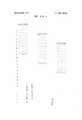
- FIG. 1 is a graphic presentation of a seismic traverse according to the present invention involving 36 detector stations and illustrating movement of the source point, switching of the active recording channels, and inactive movement of the seismic spread during the traverse period.
- FIG. 2 is a graphic illustration of source locations during a seismic traverse conducted in accordance with the present invention.
- FIG. 3 is a graphic representation of reflection point data, shown to be l2-fold coverage, obtained by employing the method illustrated in FIGS. 1 and 2.
- FIG. 4 is a graphic representation of an alternate method of seismic traverse according to the present invention involving 24 detector stations and illustrating movement of the source point, switching of the active recording channels and inactive movement of the seismic spread during a seismic traverse.
- FIG. 5 is a graphic illustration of source locations during a seismic traverse conducted in accordance with FIG. 4.
- FIG. 6 is a graphic representation of reflection point data, shown to be l8-fold coverage, obtained by employing the seismic data acquisition method illustrated in FIGS. 4 and 5.
- FIG. 7 is a graphic representation of a skip spread seismic traverse conducted in accordance with the present invention, involving 24 detector stations and illustrating movement of the source point, switching of the active recording channels and inactive movement of the seismic spread during a shoot-six-skipl 2 seismic traverse.
- FIG. 8 is a graphic representation of source locations during the seismic traverse illustrated in FIG. 7.
- FIG. 9 is a graphic illustration of reflection point data obtained by employing the seismic data acquisition method illustrated in FIGS. 7 and 8 and shown to be six-fold multiple coverage.
- FIG. 10 is a graphical representation of an alternate mode of operation for use when the switching mechanism is not employed and the number of the detector stations is equal to the number of recording channels.
- FIG. 11 illustrates the operation of the procedure in FIG. 10 and includes the subsurface reflecting points.
- FIG. 1 there is illustrated a seismic spread 10 comprising a seismic cable 12 having 36 seismic wave detectors situated in evenly spaced relation along the length thereof.
- any one of a number of commercially available seismic wave detectors may be employed within the scope of the present invention.
- Such detectors when employed on land, are generally referred to as geophones or phones and when employed in a marine environment, are generally referred to as hydrophones.
- a source 16 for the generation of seismic waves may be connected to seismic cable 12 ahead of the first one of the seismic detector stations 14.
- the source 16 may be any one of a number of acceptable means for generating seismic waves, such as an explosive device, an acoustical wave generating device or the like, within the scope of the present invention.
- the seismic spread 10 may be towed through a marine environment by a vessel or may be propelled or otherwise manipulated in a land based environment to achieve movement in the direction of the arrow in FIG. 1.
- discussion will be related particularly to application of the invention in a marine environment, although it is not intended that the invention be restricted to use in marine environment.
- the distance between the source 16 and the first detector station is shown to be equal to the detector interval among the 36 detector locations but this particular source-to-first-detector-distance is not essential to the ends of the present invention.
- the distance between the source location and the first detector is not restricted to any given length (but some distance lengths will enhance the quality of a data recording).
- the source to first detector distance however, must remain uniform throughout any given traverse.
- the detectors may be spaced evenly at 200 foot intervals along the length of the seismic cable, but again this particular distance is not intended to limit the present invention, it being obvious that other detector intervals may be employed within the spirit and scope of the invention.
- reflected signals received along the several paths from the reflection point to the various wave detection devices, will produce a resultant sum that will be proportional to the number of signals received. Perturbations following other than the postulated ray paths will not be coincident, and hence will be degraded from the reflections.
- a method of obtaining such multiple fold coverage may conveniently take the form illustrated in FIG. I where a seismic spread is depicted in the uppermost line of FIG. 1 at the initial point of a seismic data gathering traverse with detector stations 1 through 24 activated while detectors 25 through 36 are deactivated and do not transmit reflected data to a data control facility.
- a 24 channel recording circuit may be selectively connected to the various detector stations by a stepping switch or by any other conventional switching apparatus of acceptable nature.
- the switching apparatus will be operative to switch sequentially after each seismic wave to successive contiguous groups of the detector stations as the seismic cable is towed through a body of water.
- the source location or source point 16 is depicted as having moved forwardly or to theleft a distance equal to one-half of the detector interval while the switching apparatus has deactivated the first detector station and has activated detectors 2 through 25 and has allowed detectors 26 through 36 to remain in a deactivated state. It is apparent that while the physical movement of the seismic cable 12 in a forward direction is equal to one-half of the detector interval, the contiguous group of active detectors has moved rearward or to the right by an effective distance equal to one-half of the detector interval. The effective subsurface area covered for data reflection is therefore equal to one-half of the distance of cable movement.
- the seismic spread continues in its travel a sufficient distance to cause 12 source locations or source points at which time detector stations 1 through 11 will be deactivated while stations 12 through 35 will be electrically connected to the 24 channel recording circuitry.
- the activated portion of the seismic traverse is indicated by small triangular symbols as the seismic spread is towed in the direction of the arrow at the left portion of FIG. 2.
- Vertical lines 19, 20, 21 and 22 separate the active source locations from the inactive or skipped source locations as the tow physically progresses along the path established by profile markers 24.
- the resultant reflection point data acquired by the first 12 active source locations in FIG. 1 are depicted at the upper right portion of FIG. 3, illustrating that 12- fold coverage, which may be referred to as horizontal 12-fold horizontal stacking, is achieved by the present method of seismic data acquisition.
- the source 16 and the seismic cable 12 continue to be towed during the active phase of seismic data acquisition (the 12 activated source locations) at a constant speed that is sufficiently slow to prevent the development of excessive noise that might otherwise interfere with effective data acquisition.
- the entire seismic spread may be deactivated and the cable may be moved a distance equal to 12 source locations and seismic data acquisition may again begin with activation of detectors 1 through 24 as discussed above.
- the seismic spread may be moved a distance equal to 12 stations in a deactivated condition, in order to increase the average speed of seismic data acquisition, it is appropriate to accelerate the speed of the vessel to the greatest practical extent during the skipped source portion of the traverse. Upon reaching the position at which seismic data acquisition may again begin, the speed of the vessel is slowed to an optimum speed for data acquisition. It is noteworthy that the source and the detector cable continue to progress the traverse at a constant moderate speed as the switching arrangement takes place and that after 12 activated source locations and 12 dead or nonshot locations are traversed at increased towing speed, the process is repeated.
- the source is activated 12 times as the seismic spread is moved at a constant slow speed and then 12 source locations are skipped during which period the speed of the traverse can be increased substantially, thereby effectively increasing the average speed of the total traverse and reducing the average cost of data acquired. Even though the speed of the traverse is alternately increased and slowed, stacking of the desired multiplicity is effectively obtained.
- FIGS. 4 through 6 there is depicted a modified embodiment of the skip-spread seismic traverse method of data acquisition employing 24 detector stations and achieving l8-fold multiple coverage.
- a seismic spread is illustrated at 26 in FIG. 4 including a seismic cable 28 having 24 detector stations 30 connected in evenly spaced relation along the length of the cable 28.
- the source 32 is illustrated by small triangles to indicate graphically the position at which seismic waves are generated during traverse of the seismic cable 28 in the direction of the arrow depicted at the upper left portion of FIG. 4.
- the seismic data acquisition method illustrated in FIG. 4 may be referred to as the shoot-six-skip-six method, wherein a total of six active source locations are generated while the seismic cable is towed at slow constant speed by a vessel or the like.
- a switching circuit or an electronic data selection mechanism is employed to switch a total of 18 contiguous recording channels in progressive order between each source location.
- the small circles indicate that detectors 1 through 18 are activated by a switching mechanism or the like while detectors 19 through 24 are deactivated.
- detector No. 1 and detectors 20 through 24 are deactivated while the switching mechanism electrically connects the detectors 2 through 19 to the l8-channel recording circuit.
- Switching and continuous movement of the seismic cable continues through the sixth source location, as illustrated at the sixth line in FIG. 4, where detectors 1 through 5 and 24 are shown to be deactivated while detectors 6 through 23 are electrically connected to the recording system. After this has been accomplished, the result will be a symmetrical six-fold stack as illustrated at the upper right portion of FIG. 6.
- the seismic cable and source is then moved at an increased speed through a distance equal to six source locations and the seismic wave generation and recording process is again initiated with detectors 1 through 18 electrically connected to the recording circuit while detectors 19 through 24 are reactivated.
- the seismic cable 28 will, of course, be towed at a constant speed that is sufficiently slow to prevent excessive noise.
- Active source locations will continue through the next six source locations or locations 13 through 18 thereby generating seismic waves and acquiring seismic data shown in FIG. 6 as the centermost six-fold stack of seismic data.
- the seismic cable 28 may again be towed at rapid speed through a distance equal to six source locations at which time the speed of the traverse must again be slowed to a speed sufficiently slow for effective recording.
- the third active phase is again initiated at line 25 of FIG. 4 in similar manner as discussed above, thereby acquiring seismic data illustrated at the lower most sixfold stack of seismic data in FIG. 6.
- the traverse is accomplished by alternative active and inactive six source locations as the seismic cable is towed by the vessel.
- the speed of cable movement will be relatively slow during the active phases, shown by the small triangles, while the speed of the cable may be increased substantially during the inactive phases, indicated by small Xs.
- the active and inactive phases are separated graphically by vertical lines 32 through 40 in FIG. 5.
- FIGS. 7 through 9 it is apparent that the method of seismic data acquisition, according to the present invention, may be employed to achieve a lesser fold coverage, and according to the present invention such lesser seismic coverage may conveniently take the form illustrated in FIGS. 7, 8, and 9 which depict a shoot-six-skip-twelve method of seismic data acquisition.
- a seismic cable 34 is illustrated in FIG. 7 as being towed in the direction of the arrow by a vessel or by any other suitable towing device.
- the seismic cable 34 is provided with 24 detector stations 36 connected in evenly spaced relation along the length of the seismic cable.
- a seismic wave source 38 is depicted as being connected to the leading extremity of the seismic cable at a distance ahead of the leading detector equal to the average distance between the various detectors.
- the source 38 may be disposed in any other suitable distance from the leading detector as might be appropriate to enhance the quality of the data recorded. It is necessary, as indicated above, that the source to first detector distance remain uniform throughout any given traverse.
- a switching mechanism or electronic data selection system will be connected to receive seismic data transmitted from the first 18 of the detectors or hydrophones of cable 34.
- an l8-channel recording circuit may be electrically connected to the first 18 of the detectors in order to receive seismic data transmitted therefrom and to transmit the seismic data to an appropriate recording facility for visual or electronic readout.
- the seismic cable 34 has been moved forwardly, or to the left a distance equal to one-half of the average distance between the detectors and the source 38 has been energized to generate a seismic wave.
- the switching mechanism has operated to deenergize the first detector and detectors 20 through 24 while detectors 2 through 19 have been energized for seismic data acquisition.
- Seismic cable 34 continues to be towed at a speed that is constant and is sufficiently slow to prevent the development of undesirable noise. Movement of the seismic cable 34 and switching of the recording circuit will continue through line 6 where the detectors 1 through 5 and 24 will be deenergized while detectors 6 through 23 will be electrically connected to the 18- channel recording circuit. It will be observed that, after the sixth source location, as illustrated in lines 1 through 6, there will be provided six-fold multiple coverage of seismic data being received from common reflection points.
- all 24 of the detectors will be deenergized as towing of the seismic cable continues through a distance equal to 12 additional source locations where the cable will be positioned as illustrated in line 18.
- the speed of the tow may be increased substantially, thereby effectively reducing thetotal towing time necessary to move the seismic cable through a distance equal to a total of 18 source locations.
- the l8-channel recording circuit will again be electrically connected to detectors 1 through 18 and the source 38 will generate a seismic wave that will be reflected by earth substrata to the first l8 detectors for recording.
- Seismic wave generation at the next six source locations, depicted in lines 19 through 24, will then occur with switching of the l8-channel recording circuit to the various contiguous detector groups as indicated above.
- the entire seismic spread will be deenergized as towing continues at an increased speed through a distance equal to l2 source locations to a position illustrated in line 36 where seismic generation and switching of the detectors will again occur as towing is again slowed to a constant optimum speed as indicated above.
- towing of the detector cable will progress as indicated by the tow arrow and seismic waves will be generated as indicated by source location triangles along a traverse defined by profile markers. Since the towing of the seismic cable may be conducted at an increased speed during a distance equal to l2 skipped locations and slowed for seismic data acquisitions during six active source locations, it is obvious that the average speed of the tow will be substantially greater than seismic data gathering at a conventional slow towing rate.
- the present invention provides a novel method of seismic data acquisition that effectively allows an overall increase in speed of towing a seismic spread without increasing noise level above an optimum value.
- the seismic data is gathered at a constant and acceptably slow speed thereby enhancing the value of data acquired.
- the seismic cable might be towed at various speeds, it is practical to achieve the horizontal stacking technique of seismic data acquisition and to do so without increasing spacing between common reference point files.
- the invention achieves optimum horizontal noise cancellation due to close spacing of the traces.
- the invention effectively provides for seismic data acquisition of superior value which may be obtained at much faster rates and therefore at lower costs than has heretofore been practical.
- FIG. 9 illustrates the common reflection points for the methods in FIG. 7 and FIG. 8.
- the common reflection point 101 consists of traces having six different source-todetector distances equal to one detector interval, two detector intervals, three detector intervals, etc., to six detector intervals.
- This common reflection point 101 provides a good statistical average for the moveout near the source.
- Common reflection point 102 consists of traces having six different source-to-detector distances which are large in comparison with source-todetector distances for common reflection point 101.
- the source-to-detector distances for common reflection point 102 are 18 detector intervals, 19 detector intervals, etc., to 23 detector intervals.
- FIGS. 10 and 1 1 illustrate an alternative arrangement which employs the same number of detector stations as the number of recording channels. No switching means is employed. In this case illustrated, there are 24 detector groups and the distance from the source to the closest detector is equal to the spacing between detectors. Either of these can be modified since they are illustrative rather than restrictive.
- the traverse is started with the source at location A and 24 detectors, or 24 detector arrays, extending to the right of location A as illustrated in FIG. 10.
- the source is excited at location A and the outputs of detectors 1 through 24 are recorded in the usual manner.
- the source and detectors are slowly moved one-half a detector interval to the left. When the source reaches location B, the source is excited and the output of all 24 detectors, or detector arrays, are recorded.
- the process is repeated for location C., etc., through location F.
- the assembly consisting of source and detectors is then moved to the left as fast as practical past locations G, H, etc., to location K and the source is not excited at any of these 18 locations.
- the assembly is slowed down to a reasonable speed for recording.
- the source is excited at location L and the data from all 24 detectors is recorded.
- the assembly continues to the left at a slow constant speed, the source is excited at locations M through Q, and a recording of each source excitation is made from all 24 detectors.
- the speed of the assembly is then increased past locations R, S, etc., to location T.
- the speed is decreased to the slow constant speed for recording from locations U through V.
- the process is repeated along the traverse.
- FIG. 1 1 is a detail of the initial portion of the process.
- the initial position is shown at the top of FIG. 11 with the source at location A and 24 detectors to the right.
- the assembly is moved slowly to the left as incidacted by the Tow arrow, but the next source location B is indicated below the original position for clarity.
- a slow constant speed is used for recording through location F.
- the reflection point for the source at location A and detector 1 is at the midpoint between source A and detector 1 and is indicated by the small circle A1. Similar reflection points to the other detectors are to the right, such as, A12 from detector 12 and A24 from detector 24.
- the reflection points from the source at location B are shown slightly lower and to the left.
- the process continues through the source at location F indicated and the reflection points are F1 to F24.
- Data from a common reflection point W is indicated at A12, B13, etc., to F17. There are six of these paths, hence, six-fold coverage.
- Reflection points for sources at locations L through Q is indicated in the block from L1 to L24 and down to O1 to Q24.
- Common reflection point Y has two reflection points from E and F and four points from L through 0, namely E1, F2, L21, M22, N23 and 024. It can be observed that each common reflection point has six different reflection paths. The number of detectors could be increased to obtain an increase in multiplicity of the coverage or to decrease number of locations for sources or similar modifications.
- each detector is indicated as a detector but in practice usually an array of detectors connected together will be used in place of a single detector.
- a method of marine seismic exploration wherein a seismic spread having a plurality of seismic detectors evenly spaced along the length thereof is towed through a body of water by a vessel, said seismic spread having leading and trailing extremities, seismic data recording means being provided and including a lesser number of recording channels than the number of said seismic detectors, said method comprising:
- a method of marine seismic exploration wherein a seismic spread having a plurality of seismic detectors evenly spaced along the length thereof is towed through a body of water by a vessel, said seismic spread having leading and trailing extremities, seismic data recording means being provided and including a lesser number of recording channels than the number of said seismic detectors, said method comprising:
- towing said spread through the body of water at an optimum constant speed for efficient data acquisition initiating data acquisition with said recording channels connected to the leading ones of said number of seismic detectors in said seismic spread; generating successive seismic waves at a shotpoint fixedly located with respect to said seismic spread as said spread is moved through said body of water; switching said recording channels at detector intervals corresponding to said shotpoint spacing toward the trailing extremity of said seismic spread after each seismic wave generation; continuing said seismic wave generation and switching of said recording channels during a first predetermined length of movement of said seismic spread; discontinuing generation of seismic waves and switching of said recording channels during a second predetermined length of movement of said seismic spread; and towing said seismic spread through said body of water at a speed in excess of said optimum constant speed during said second predetermined length of movement of said seismic spread.
- said switching of said recording channels comprises switching each of said recording channels one detector interval toward the trailing extremity of said seismic spread after each seismic wave generation.
- said predetermined length of movement of said seismic spread equals substantially one-half of the length of said seismic spread.
- said shotpoint is generated at a distance ahead of the first of said group of seismic detectors equal to the average distance between said detectors of said seismic spread.
- said shotpoint is generated at a distance ahead of the first of said group of seismic detectors equal to the average distance between said detectors of said seismic spread;
- a method of seismic exploration wherein a seismic spread having a plurality of seismic detector means evenly spaced along the length thereof is moved in one direction, said seismic spread having leading and trailing extremities, said detectors being capable of recording reflected seismic data at any time, said method comprising:
- a method of seismic exploration wherein a seismic spread having a plurality of seismic detector means evenly spaced along the length thereof is moved in one direction, said seismic spread having leading and trailing extremities, said detectors being capable of recording reflected seismic data at any time, said method comprising:
- all of said detector means are active to receive and transmit seismic information
- said switching of said selected detector means being accomplished by switching said data collection one detector interval subsequent to each seismic wave generation.
- a method of marine seismic exploration for achieving continuous multiple fold coverage of a subsurface environment wherein a seismic spread having a seismic source and a plurality of seismic detectors evenly spaced along the length thereof is towed along a traverse having uniformly spaced locations and a contiguous group of recording channels is employed to receive signals from selected contiguous groups of said seismic detectors, said method comprising:
- steps (d), (e) and (f) are repeated along the traverse.
- a method of seismic exploration for achieving continuous multiple fold coverage of a subsurface environment wherein a seismic spread having a seismic source and a plurality of seismic detectors evenly spaced along the length thereof is located along a traverse having uniformly spaced locations and a contiguous group of recording channels is employed to receive signals from selected contiguous groups of said seismic detectors, said method comprising:
- step (b) exciting the source and recording the signals received from said different consecutive series of said seismic detectors;
- step (f) successively repeating step (f) then step (g) along the traverse.
Landscapes
- Life Sciences & Earth Sciences (AREA)
- Physics & Mathematics (AREA)
- Engineering & Computer Science (AREA)
- Remote Sensing (AREA)
- Acoustics & Sound (AREA)
- Environmental & Geological Engineering (AREA)
- Geology (AREA)
- General Life Sciences & Earth Sciences (AREA)
- General Physics & Mathematics (AREA)
- Geophysics (AREA)
- Oceanography (AREA)
- Geophysics And Detection Of Objects (AREA)
Applications Claiming Priority (1)
| Application Number | Priority Date | Filing Date | Title |
|---|---|---|---|
| US19047871A | 1971-10-19 | 1971-10-19 |
Publications (1)
| Publication Number | Publication Date |
|---|---|
| US3790929A true US3790929A (en) | 1974-02-05 |
Family
ID=22701510
Family Applications (1)
| Application Number | Title | Priority Date | Filing Date |
|---|---|---|---|
| US00190478A Expired - Lifetime US3790929A (en) | 1971-10-19 | 1971-10-19 | Skip-spread method for seismic surveying |
Country Status (4)
| Country | Link |
|---|---|
| US (1) | US3790929A (enExample) |
| CA (1) | CA958108A (enExample) |
| FR (1) | FR2156801B1 (enExample) |
| GB (1) | GB1402343A (enExample) |
Cited By (5)
| Publication number | Priority date | Publication date | Assignee | Title |
|---|---|---|---|---|
| US4316266A (en) * | 1976-03-30 | 1982-02-16 | Societe Nationale Elf Aquitaine (Production) | Method of reflection point correlation seismic surveying |
| US4405999A (en) * | 1980-12-31 | 1983-09-20 | Mobil Oil Corporation | Method for collecting and generating composite trace signals with improved signal to noise ratios |
| US4467460A (en) * | 1979-07-30 | 1984-08-21 | The Standard Oil Company | Seismic data acquisition method |
| US4677598A (en) * | 1983-03-25 | 1987-06-30 | Standard Oil Company (Indiana) | Seismic data acquisition method |
| US6629037B1 (en) * | 2000-06-26 | 2003-09-30 | Westerngeco, L.L.C. | Optimal paths for marine data collection |
Families Citing this family (1)
| Publication number | Priority date | Publication date | Assignee | Title |
|---|---|---|---|---|
| NO148309C (no) * | 1981-05-26 | 1983-09-14 | Norway Geophysical Co | Fremgangsmaate ved innsamling og systematisering av data ved seismiske undersoekelser til sjoes |
Citations (4)
| Publication number | Priority date | Publication date | Assignee | Title |
|---|---|---|---|---|
| US3105568A (en) * | 1959-12-07 | 1963-10-01 | Jersey Prod Res Co | Seismic profiling system |
| US3352377A (en) * | 1966-01-17 | 1967-11-14 | Mobil Oil Corp | Multiple coverage seismic exploration utilizing two groups of detectors separated by a gap |
| US3412373A (en) * | 1967-02-01 | 1968-11-19 | Sun Oil Company Philadelphia | Method of seismographic analysis |
| US3437989A (en) * | 1966-06-07 | 1969-04-08 | Texas Instruments Inc | Apparatus and method for continuous marine multichannel seismic exploration |
Family Cites Families (1)
| Publication number | Priority date | Publication date | Assignee | Title |
|---|---|---|---|---|
| US3368191A (en) * | 1965-12-29 | 1968-02-06 | Mobil Oil Corp | Continuous marine seismic exploration with multiple subsurface coverage |
-
1971
- 1971-10-19 US US00190478A patent/US3790929A/en not_active Expired - Lifetime
-
1972
- 1972-06-16 CA CA144,943A patent/CA958108A/en not_active Expired
- 1972-07-06 GB GB3173372A patent/GB1402343A/en not_active Expired
- 1972-10-18 FR FR7236937A patent/FR2156801B1/fr not_active Expired
Patent Citations (4)
| Publication number | Priority date | Publication date | Assignee | Title |
|---|---|---|---|---|
| US3105568A (en) * | 1959-12-07 | 1963-10-01 | Jersey Prod Res Co | Seismic profiling system |
| US3352377A (en) * | 1966-01-17 | 1967-11-14 | Mobil Oil Corp | Multiple coverage seismic exploration utilizing two groups of detectors separated by a gap |
| US3437989A (en) * | 1966-06-07 | 1969-04-08 | Texas Instruments Inc | Apparatus and method for continuous marine multichannel seismic exploration |
| US3412373A (en) * | 1967-02-01 | 1968-11-19 | Sun Oil Company Philadelphia | Method of seismographic analysis |
Cited By (6)
| Publication number | Priority date | Publication date | Assignee | Title |
|---|---|---|---|---|
| US4316266A (en) * | 1976-03-30 | 1982-02-16 | Societe Nationale Elf Aquitaine (Production) | Method of reflection point correlation seismic surveying |
| US4467460A (en) * | 1979-07-30 | 1984-08-21 | The Standard Oil Company | Seismic data acquisition method |
| US4405999A (en) * | 1980-12-31 | 1983-09-20 | Mobil Oil Corporation | Method for collecting and generating composite trace signals with improved signal to noise ratios |
| US4677598A (en) * | 1983-03-25 | 1987-06-30 | Standard Oil Company (Indiana) | Seismic data acquisition method |
| US6629037B1 (en) * | 2000-06-26 | 2003-09-30 | Westerngeco, L.L.C. | Optimal paths for marine data collection |
| AU2001271539B2 (en) * | 2000-06-26 | 2005-05-12 | Westerngeco Seismic Holdings Ltd. | Optimal paths for marine data collection |
Also Published As
| Publication number | Publication date |
|---|---|
| GB1402343A (en) | 1975-08-06 |
| FR2156801A1 (enExample) | 1973-06-01 |
| FR2156801B1 (enExample) | 1976-05-21 |
| CA958108A (en) | 1974-11-19 |
| AU4444672A (en) | 1974-01-17 |
Similar Documents
| Publication | Publication Date | Title |
|---|---|---|
| US4715020A (en) | Simultaneous performance of multiple seismic vibratory surveys | |
| US5430689A (en) | Method for acquiring marine seismic data having statistically distributed azimuths and offsets | |
| US3885225A (en) | Broad line seismic profiling | |
| US3921124A (en) | Marine 3-D seismic method using source position control | |
| US3806863A (en) | Method of collecting seismic data of strata underlying bodies of water | |
| US5524100A (en) | Method for deriving water bottom reflectivity in dual sensor seismic surveys | |
| US7679990B2 (en) | Methods for acquiring and processing seismic data from quasi-simultaneously activated translating energy sources | |
| US4636956A (en) | Method and device for optimization of seismic data | |
| US4058791A (en) | Method and apparatus for processing seismic signals from low energy sources | |
| US3934220A (en) | Method of seismic exploration for penetrating diffraction barriers and/or surveying beneath obstacles | |
| US5511039A (en) | Method of performing high resolution crossed-array seismic surveys | |
| US6961284B2 (en) | Source array for use in marine seismic exploration | |
| US4001770A (en) | Roll-a-long three-dimensional common depth point exploration | |
| US3529282A (en) | Method for determining in-line and cross dip employing cross steering of seismic data | |
| US3105568A (en) | Seismic profiling system | |
| US4330873A (en) | Aplanatic geophysical exploration system | |
| US3746122A (en) | Multi-directional seismic exploration methods | |
| US4357689A (en) | Seismic data gathering method | |
| US3747056A (en) | High resolution reflection shooting with data mixing | |
| US4405999A (en) | Method for collecting and generating composite trace signals with improved signal to noise ratios | |
| US3209322A (en) | Method of seismic prospecting | |
| US3790929A (en) | Skip-spread method for seismic surveying | |
| US3278893A (en) | Reducing the effect of multiple reflections of seismic wave signals | |
| US3088541A (en) | Seismic exploration | |
| US3766519A (en) | Method for processing surface detected seismic data to plotted representations of subsurface directional seismic data |
Legal Events
| Date | Code | Title | Description |
|---|---|---|---|
| AS | Assignment |
Owner name: HALLIBURTON GEOPHYSICAL SERVICES, INC., TEXAS Free format text: ASSIGNMENT OF ASSIGNORS INTEREST.;ASSIGNOR:G & H MANAGEMENT COMPANY;REEL/FRAME:005252/0162 Effective date: 19890918 Owner name: G & H MANAGEMENT COMPANY Free format text: CHANGE OF NAME;ASSIGNOR:GEOSOURCE, INC.;REEL/FRAME:005252/0167 Effective date: 19881129 |