US3789701A - Timer positioning mechanism - Google Patents
Timer positioning mechanism Download PDFInfo
- Publication number
- US3789701A US3789701A US00307179A US3789701DA US3789701A US 3789701 A US3789701 A US 3789701A US 00307179 A US00307179 A US 00307179A US 3789701D A US3789701D A US 3789701DA US 3789701 A US3789701 A US 3789701A
- Authority
- US
- United States
- Prior art keywords
- pin
- disc
- stop
- timer
- masking
- Prior art date
- Legal status (The legal status is an assumption and is not a legal conclusion. Google has not performed a legal analysis and makes no representation as to the accuracy of the status listed.)
- Expired - Lifetime
Links
- 230000000873 masking effect Effects 0.000 claims abstract description 28
- 238000005406 washing Methods 0.000 claims description 8
- 238000009877 rendering Methods 0.000 claims description 2
- 230000000994 depressogenic effect Effects 0.000 abstract description 5
- 229920000742 Cotton Polymers 0.000 description 4
- 230000000903 blocking effect Effects 0.000 description 2
- 230000000881 depressing effect Effects 0.000 description 1
- 239000004744 fabric Substances 0.000 description 1
- 238000000034 method Methods 0.000 description 1
- 238000012163 sequencing technique Methods 0.000 description 1
Images


Classifications
-
- G—PHYSICS
- G05—CONTROLLING; REGULATING
- G05G—CONTROL DEVICES OR SYSTEMS INSOFAR AS CHARACTERISED BY MECHANICAL FEATURES ONLY
- G05G21/00—Mechanical apparatus for control of a series of operations, i.e. programme control, e.g. involving a set of cams
-
- H—ELECTRICITY
- H01—ELECTRIC ELEMENTS
- H01H—ELECTRIC SWITCHES; RELAYS; SELECTORS; EMERGENCY PROTECTIVE DEVICES
- H01H43/00—Time or time-programme switches providing a choice of time-intervals for executing one or more switching actions and automatically terminating their operations after the programme is completed
- H01H43/10—Time or time-programme switches providing a choice of time-intervals for executing one or more switching actions and automatically terminating their operations after the programme is completed with timing of actuation of contacts due to a part rotating at substantially constant speed
-
- D—TEXTILES; PAPER
- D06—TREATMENT OF TEXTILES OR THE LIKE; LAUNDERING; FLEXIBLE MATERIALS NOT OTHERWISE PROVIDED FOR
- D06F—LAUNDERING, DRYING, IRONING, PRESSING OR FOLDING TEXTILE ARTICLES
- D06F2101/00—User input for the control of domestic laundry washing machines, washer-dryers or laundry dryers
- D06F2101/14—Time settings
-
- D—TEXTILES; PAPER
- D06—TREATMENT OF TEXTILES OR THE LIKE; LAUNDERING; FLEXIBLE MATERIALS NOT OTHERWISE PROVIDED FOR
- D06F—LAUNDERING, DRYING, IRONING, PRESSING OR FOLDING TEXTILE ARTICLES
- D06F2105/00—Systems or parameters controlled or affected by the control systems of washing machines, washer-dryers or laundry dryers
- D06F2105/52—Changing sequence of operational steps; Carrying out additional operational steps; Modifying operational steps, e.g. by extending duration of steps
-
- D—TEXTILES; PAPER
- D06—TREATMENT OF TEXTILES OR THE LIKE; LAUNDERING; FLEXIBLE MATERIALS NOT OTHERWISE PROVIDED FOR
- D06F—LAUNDERING, DRYING, IRONING, PRESSING OR FOLDING TEXTILE ARTICLES
- D06F34/00—Details of control systems for washing machines, washer-dryers or laundry dryers
- D06F34/28—Arrangements for program selection, e.g. control panels therefor; Arrangements for indicating program parameters, e.g. the selected program or its progress
-
- Y—GENERAL TAGGING OF NEW TECHNOLOGICAL DEVELOPMENTS; GENERAL TAGGING OF CROSS-SECTIONAL TECHNOLOGIES SPANNING OVER SEVERAL SECTIONS OF THE IPC; TECHNICAL SUBJECTS COVERED BY FORMER USPC CROSS-REFERENCE ART COLLECTIONS [XRACs] AND DIGESTS
- Y10—TECHNICAL SUBJECTS COVERED BY FORMER USPC
- Y10T—TECHNICAL SUBJECTS COVERED BY FORMER US CLASSIFICATION
- Y10T74/00—Machine element or mechanism
- Y10T74/14—Rotary member or shaft indexing, e.g., tool or work turret
Definitions
- the disc has various radially and circumferentially positioned holes into one of which a selected pin may drop to thereby correctly position the timer at the start of the selected cycle.
- Three holes are provided in the disc on the radius of the soak" pin and a masking arrangement covers or uncovers, as the case may be, the soak" holes so only that hole which properly combines with the selected cycle is operative.
- the masking arrangement is actuated by one of the possible cycle pins. Therefore, a soak period may be selected to precede any of a number of cycles while employing only one soak button and one soak" pin.
- This invention provides a masking arrangement coupled with multiple soak positions and actuated by wash cycle selections to limit the effective soak position to the one properly preceding the selected cycle.
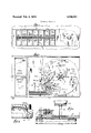
- FIG. 1 is a plan view of an assembly ofa timer, selection buttons and the selection mechanism. Only the selection buttons and timer knob are visible to the user.
- FIG. 2 is a split, enlarged view of the extreme left and right portions of FIG. 1.
- FIG. 3 is a fragmentary side elevation from line 3-3 in FIG. 2.
- FIG. 4 is a view of the pin and disc arrangement from line 44 in FIG. 2.
- FIG. 5 is an exploded perspective of the disc and mask assembly.
- FIG. 6 is a view showing the manner in which the mask is actuated. This is a meandering section on line 66 of FIG. 10.
- FIGS. 7-10 are similar views showing the relative positions of the mask, disc and selected pins for various possible soak positions.
- buttons at the left in FIG. 1 are used to select the desired function or cycle of the machine.
- the four right-hand buttons do not select a rotary position of the timer but electrically modify a selection in the case ofthree buttons and the cancel button cancels all previous selections.
- the pre-wash and soak buttons can be selected in combination with certain other buttons.
- the remaining buttons are mutually exclusive in that depressing and latching one will cancel a prior selection from among that group.
- Each of the ten buttons on the left will actuate or set a pin which functions to select the rotary position of the timer at the right of FIG. I.
- the details ofthc timer are not shown in the drawings.
- the timer may be any desired type.
- the pins are denoted by letter designations on the drawings to simplify orientation to the holes in the disc, the holes being designated by similar letters which correspond to the selection buttons.
- the soak button selects pin S which will find" hole S.
- Each pin has an enlarged central portion between the plates 20,22 which is engaged by the associated wire end. The ends of the pin guide the pin and the lower end engages the disc.
- a bearing plate 30 is fixed to the underside of disc 24 by screws 32,32 with the radial keys 34 engaging slots 36 in the disc and the central bushing 38 serving to mount the disc and plate on the timer shaft.
- the plate mounts on the disc with rim 40 against the underside of the disc so annular lip 42 is spaced from the disc with the hub 44 of stamped and formed member 46 captured between the disc and lip 42 for rotational movement relative to the disc.
- the member has a depending finger 48 engaged by the end 50 of spring 52 coiled around the bushing 38 and engaging pin 54 fixed in the bottom of the hub. This biases the member clockwise to the limit position determined by engagement of the vertical front faces of actuators projecting up through slots in the disc.
- the member 46 has arms supporting actuators. Actuator 56 projects up through slot 58 and another actuator 60 projects through slot 62. These two acutators 56,60 lie on the radius of Knitted Fabric pin KF and will be engaged by pin KF if it has been set. When so engaged, member 46 is restrained from moving with the disc and various masks (80,82,84) are moved relative to certain holes (S, PP+S, KF+S) in the disc. As movement continues, the sloping face of the actuator will be engaged by the end of the slot to cam the actuator down and disengage the mask for return to its normal position, its function having been served.
- FIG. 7 the pin 5 is designated as actuated by being shaded and is shown in the hole 8.
- the pins KF, PPW, and PPC are on the same radius as actuators 60, 68 and 74, respectively. Had any of these pins been set, it would have engaged its associated actuator to move mask 80 across hole S to prevent entry at that position to bypass that potential position. Subsequently the engaged actuator would be cammed down to release the pin. ln FIG. 8 both CLW and S have been set. The soak" position is the same. Thus soak only (FIG. 7) or soak plus Cotton, Linens, White (FIG. 8) result in pin 5 finding the same starting point.
- pin S, PP+S find" the proper hole from the three potential holes, 8. PP+S and KF+S.
- the associated actuator (68, 74,60) will move mask 80 to block hole 5 and bypass the position.
- lf on the other hand, only S or S+CLW have been set, pin S will drop in the hole to position the timer. If S has not been set, normal positioning is effective.
- Pin S should drop into hole PP+S only if one of the two Permanent Press cycles has been selected. Therefore, mask 82 should be moved to expose PP+S only by pin PPW or PPC engaging actuator 68 or 74. No other pins will move mask 82 to its inoperative position.
- hole KF+S can be exposed only by pin KF engaging actuator 56 to move mask 84 to its inoperative position.
- a plurality of selectable means mounted adjacent the member for movement between active and inactive positions.
- each of said selectable means having an associated stop means whereby a selectable means in active position will engage its associated stop means at a predetermined desired and selected position in the path of movement of the member,
- one of the selectable means having a plurality of associated stop means whereby a plurality of selected positions exist in conjunction with said one select able means
- Apparatus for selecting a desired position of a device including a rotary disc,
- each of the pins being at different radial distance from the axis of rotation of the disc whereby there is a separate rotational path on the disc for each pin,
- one rotational path being provided with plural stops means whereby the specific pin associated therewith potentially has plural positions in which it engages a stop means
- actuating means engageable by certain pins to actuate said masking means between said active and in active positions.
- said plural stop means comprising multiple holes at equal radial distance from said axis and circumfer entially spaced
- said masking means being operative to prevent entry of a pin when in active position.
- Apparatus according to claim 4 in which the masking means associated with one of said multiple holes is normally in inactive position and is moved to active position by engagement of any of certain selected pins with the actuating means.
- Apparatus according to claim 5 in which the masking means associated with another of said multiple holes is normally in active position and is moved to inactive position by engagement of a certain selected pin with the actuating means.
- said means responsive to actuation of both selecting means being engageable by the pin associated with the actuated program selection means and operative to render only one of said plurality of positions effective 9.
- the disc has stop means at each of said plurality of positions and said responsive means comprises a masking device movable between an active position masking a stop means and an inactive position in which the stop means may be engaged by the pin associated with the selected program.
Landscapes
- Physics & Mathematics (AREA)
- General Physics & Mathematics (AREA)
- Engineering & Computer Science (AREA)
- Automation & Control Theory (AREA)
- Control Of Washing Machine And Dryer (AREA)
Applications Claiming Priority (1)
| Application Number | Priority Date | Filing Date | Title |
|---|---|---|---|
| US30717972A | 1972-11-16 | 1972-11-16 |
Publications (1)
| Publication Number | Publication Date |
|---|---|
| US3789701A true US3789701A (en) | 1974-02-05 |
Family
ID=23188597
Family Applications (1)
| Application Number | Title | Priority Date | Filing Date |
|---|---|---|---|
| US00307179A Expired - Lifetime US3789701A (en) | 1972-11-16 | 1972-11-16 | Timer positioning mechanism |
Country Status (3)
| Country | Link |
|---|---|
| US (1) | US3789701A (enExample) |
| JP (1) | JPS4981885A (enExample) |
| AU (1) | AU466279B2 (enExample) |
Cited By (3)
| Publication number | Priority date | Publication date | Assignee | Title |
|---|---|---|---|---|
| US4060702A (en) * | 1976-01-09 | 1977-11-29 | Wallace Leon Linn | Timer switch assembly having escapement mechanism |
| US20050230229A1 (en) * | 2004-03-17 | 2005-10-20 | Kurek Stephen R | Indexing mechanism |
| US8497424B2 (en) | 2010-05-25 | 2013-07-30 | Leviton Manufacturing Co., Inc. | Universal box system |
Citations (2)
| Publication number | Priority date | Publication date | Assignee | Title |
|---|---|---|---|---|
| US3236123A (en) * | 1963-02-18 | 1966-02-22 | Controls Co Of America | Timer |
| US3330172A (en) * | 1965-08-20 | 1967-07-11 | Mallory & Co Inc P R | Timer indexing mechanism |
-
1972
- 1972-11-16 US US00307179A patent/US3789701A/en not_active Expired - Lifetime
-
1973
- 1973-08-08 AU AU59024/73A patent/AU466279B2/en not_active Expired
- 1973-09-12 JP JP48102268A patent/JPS4981885A/ja active Pending
Patent Citations (2)
| Publication number | Priority date | Publication date | Assignee | Title |
|---|---|---|---|---|
| US3236123A (en) * | 1963-02-18 | 1966-02-22 | Controls Co Of America | Timer |
| US3330172A (en) * | 1965-08-20 | 1967-07-11 | Mallory & Co Inc P R | Timer indexing mechanism |
Cited By (5)
| Publication number | Priority date | Publication date | Assignee | Title |
|---|---|---|---|---|
| US4060702A (en) * | 1976-01-09 | 1977-11-29 | Wallace Leon Linn | Timer switch assembly having escapement mechanism |
| US20050230229A1 (en) * | 2004-03-17 | 2005-10-20 | Kurek Stephen R | Indexing mechanism |
| US7375298B2 (en) * | 2004-03-17 | 2008-05-20 | Leviton Manufacturing Co., Inc. | Indexing mechanism |
| US8497424B2 (en) | 2010-05-25 | 2013-07-30 | Leviton Manufacturing Co., Inc. | Universal box system |
| US9543093B2 (en) | 2010-05-25 | 2017-01-10 | Leviton Manufacturing Co., Inc. | Universal box system |
Also Published As
| Publication number | Publication date |
|---|---|
| AU466279B2 (en) | 1975-10-23 |
| AU5902473A (en) | 1975-02-13 |
| JPS4981885A (enExample) | 1974-08-07 |
Similar Documents
| Publication | Publication Date | Title |
|---|---|---|
| US3913506A (en) | Pattern selection system for sewing machines | |
| GB575625A (en) | Improvements in and relating to clothes washing machines | |
| US3789701A (en) | Timer positioning mechanism | |
| US4413164A (en) | Timer with manual means for disabling a switch | |
| US3626452A (en) | Multiposition bidirectional rotary means for a switch or the like | |
| US3373253A (en) | Program switch | |
| US2536256A (en) | Program selector switch | |
| US3371170A (en) | Manual drive means for a timer shaft | |
| US3852554A (en) | Bidirectional rotary push-button switch | |
| US2685625A (en) | Timer for food mixers | |
| US3528315A (en) | Control knob construction and the like | |
| US2717158A (en) | Random selector for amusement device or the like | |
| US3613475A (en) | Device for the preselection of a program | |
| US3801753A (en) | Dial type wafer printed circuit switch | |
| US2973672A (en) | Timer | |
| US3304398A (en) | Snap-in push button operator | |
| US3863052A (en) | Mechanical counter | |
| US3648139A (en) | Apparatus for moving a member to a selected position | |
| US3236123A (en) | Timer | |
| US3074282A (en) | Timer | |
| US3090843A (en) | Timer mechanism | |
| US2861235A (en) | Servosystem control unit for antenna rotators | |
| US3873198A (en) | Apparatus for actuating the starting and arresting devices of electrostatic copying machines | |
| US2297152A (en) | Automatic radio tuning control | |
| US3119997A (en) | Multi-color indicator |
Legal Events
| Date | Code | Title | Description |
|---|---|---|---|
| AS | Assignment |
Owner name: CONTROLS COMPANY OF AMERICA, 9655 W. SORENG AVENUE Free format text: ASSIGNMENT OF ASSIGNORS INTEREST.;ASSIGNOR:SINGER COMPANY, THE;REEL/FRAME:004505/0515 Effective date: 19860110 |
|
| AS | Assignment |
Owner name: EATON CORPORATION, EATON CENTER, 1111 SUPERIOR AVE Free format text: ASSIGNMENT OF ASSIGNORS INTEREST.;ASSIGNOR:CONTROLS COMPANY OF AMERICA;REEL/FRAME:004614/0433 Effective date: 19861002 |