US3789363A - Selector system for automatic phonographs - Google Patents
Selector system for automatic phonographs Download PDFInfo
- Publication number
- US3789363A US3789363A US00297423A US3789363DA US3789363A US 3789363 A US3789363 A US 3789363A US 00297423 A US00297423 A US 00297423A US 3789363D A US3789363D A US 3789363DA US 3789363 A US3789363 A US 3789363A
- Authority
- US
- United States
- Prior art keywords
- record
- pushbuttons
- circuit means
- pushbutton
- switch
- Prior art date
- Legal status (The legal status is an assumption and is not a legal conclusion. Google has not performed a legal analysis and makes no representation as to the accuracy of the status listed.)
- Expired - Lifetime
Links
- 230000007246 mechanism Effects 0.000 claims abstract description 15
- 238000012163 sequencing technique Methods 0.000 claims abstract description 9
- 238000003860 storage Methods 0.000 claims abstract description 9
- 230000000694 effects Effects 0.000 claims abstract description 7
- 230000004044 response Effects 0.000 claims description 22
- XUIMIQQOPSSXEZ-UHFFFAOYSA-N Silicon Chemical compound [Si] XUIMIQQOPSSXEZ-UHFFFAOYSA-N 0.000 claims description 21
- 229910052710 silicon Inorganic materials 0.000 claims description 21
- 239000010703 silicon Substances 0.000 claims description 21
- 230000000881 depressing effect Effects 0.000 claims description 7
- 230000003213 activating effect Effects 0.000 claims description 3
- 230000000007 visual effect Effects 0.000 claims description 2
- 230000004913 activation Effects 0.000 abstract description 2
- 239000003990 capacitor Substances 0.000 description 12
- 230000006870 function Effects 0.000 description 11
- 238000003825 pressing Methods 0.000 description 10
- 238000000034 method Methods 0.000 description 9
- 230000000994 depressogenic effect Effects 0.000 description 8
- 230000008569 process Effects 0.000 description 8
- 230000006835 compression Effects 0.000 description 3
- 238000007906 compression Methods 0.000 description 3
- 239000012212 insulator Substances 0.000 description 3
- 230000001960 triggered effect Effects 0.000 description 3
- 238000010586 diagram Methods 0.000 description 2
- 238000007599 discharging Methods 0.000 description 2
- 238000004519 manufacturing process Methods 0.000 description 1
- 230000006386 memory function Effects 0.000 description 1
- 230000004048 modification Effects 0.000 description 1
- 238000012986 modification Methods 0.000 description 1
- 208000003580 polydactyly Diseases 0.000 description 1
- BALXUFOVQVENIU-KXNXZCPBSA-N pseudoephedrine hydrochloride Chemical compound [H+].[Cl-].CN[C@@H](C)[C@@H](O)C1=CC=CC=C1 BALXUFOVQVENIU-KXNXZCPBSA-N 0.000 description 1
- 238000007670 refining Methods 0.000 description 1
- 239000004334 sorbic acid Substances 0.000 description 1
- 230000003245 working effect Effects 0.000 description 1
Images


Classifications
-
- G—PHYSICS
- G11—INFORMATION STORAGE
- G11B—INFORMATION STORAGE BASED ON RELATIVE MOVEMENT BETWEEN RECORD CARRIER AND TRANSDUCER
- G11B19/00—Driving, starting, stopping record carriers not specifically of filamentary or web form, or of supports therefor; Control thereof; Control of operating function ; Driving both disc and head
- G11B19/02—Control of operating function, e.g. switching from recording to reproducing
- G11B19/08—Control of operating function, e.g. switching from recording to reproducing by using devices external to the driving mechanisms, e.g. coin-freed switch
Definitions
- ABSTRACT A selector system for coin-operated automatic phonographs employing a plurality of manually operated pushbutton control switches, representing selection digits in conjunction with associated electronic circuitry having a memory or information storage capability whereby the activation of a record selector assembly and transfer mechanism to efiect the play of a selected recording is preconditioned on predetermined operational sequencing of multiple control switches and circuits as programmed by specific digit combinations.
- This invention relates generally to automatic coin controlled phonographs and more particularly to improved means for selecting a recording for play.
- the present invention comprises novel electronic circuitry controlled by manually operated switches for permitting the operator of an automatic coin controlled phonograph, of the order taught in US. Pat. No. 3,183,005 issued May 11, 1965, for example, to select particular recordings by sequentially actuating predetermined combinations of control pushbuttons, each pushbutton representing a specific digit.
- Electronic information represented by a particular sequence of digits, productive of a particular sequential operation of control switches, is utilized to sequentially enable a succession of electronic circuits arranged to activate a selector assembly and record transfer mechanism capable of removing a selected recording from a record storage magazine, placing the record in proper play side up position on the phonograph turntable and returning the record to storage upon completion of the play.
- the control circuitry of this invention comprises particular circuit arrangements utilizing silicon controlled rectifiers, or SCRs, to perform switching functions necessary to enable the selector assembly to activate the record transfer mechanism; the SCRs having an electrical characteristic that, once having been triggered or activated, they remain in a state of conductivity under certain circuit conditions. Utilizing this memory feature permits multiple operations of one or more control switches to produce a desired sequencing of digital combinations regulative of associated circuits for determining a particular record play.
- Another important object of this invention is to provide a digital selector system employing electronic memory functions to precondition the selection and play of musical recordings on predetermined combinations and sequences of control switch and circuit operations.
- a still further object of this invention is to provide a selector system utilizing digital control pushbuttons as encoder means in which multiple digit combinations are used to identify specific musical selections stored on records in a multiple record storage system.
- Still another important object of this invention is to provide a selector system for automatic coin controlled phonographs in which the playing of a musical selection is preconditioned on the deposit and acceptance of predetermined coin values and the sequential operation of predetermined combinations of control switches.
- FIG. I is a schematic circuit diagram illustrating the selector system of this invention.
- FIGS. 2-6 are additional circuit diagrams, similar to FIG. 1, with portions thereof shown in heavy lines to illustrate energized portions of the circuit during successive operational conditions;
- FIG. 7 is an enlarged showing of the disabling circuit shown in operating condition in FIG. 3;
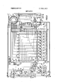
- FIG. 8 is a front elevational view of a pushbutton assembly utilized with the circuit of FIG. 1;
- FIG. 9 is a cross-sectional view taken at vantage line 9-9 of FIG. 8.
- FIG. 10 is another front elevational view, similar to FIG. 8, showing operational positioning of certain components thereof.
- FIG. 1 illustrates schematically a preferred embodiment of the digital selector system according to this invention. It will be understood therefrom that electric energy in the order of 25 volts AC, at power input terminal and +32 volts DC at power input terminal 16 is supplied over an appropriate supply circuit, having return ground terminal 17.
- a manually operable pushbutton assembly indicated at 18 and generally of the order of the manual selection means disclosed in U. S. Pat. No. 3,247,737, issued Apr. 26, 1966 may be utilized, with slight modification, to include ten push-buttons each operating multiple banks or levels of switch contacts, three of which are indicated schematically in FIG. 1 at 19, 21 and 22.
- the several levels of switch contacts are mechanically interconnected or ganged such that pressing any one pushbutton operates corresponding switch contacts in each of the switch levels.
- each level of switch contacts responds to a related selection in the three digit input for the pushbutton assembly: that is, the first level 19 responds to the first digit, the second level 21 responds to the second digit, and the third level 22 responds to the third digit, in a manner illustrated in FIGS. 2 through 6, to be described in detail presently.
- each switch typified at 23, 24 and 26, in levels one, two and three, respectively, corresponds to one of ten particular digits reading from 0 through 9 inclusive.
- the intelligence represented by three digits is necessary to make a record selection as follows:
- the first digit determines the side of the record to be played. Since there are only'two such sides, only the first two digits in switch level 19, such as digit numerals l or 2 are used for first digit determination of any three-digit selection combination. As will appear later, the first level of switch contacts 19 operates a first level SCR bank 27 which ultimately causes the proper side of the record to be played. If a digit higher than 2 is used, the operator is required to reinitiate theselection procedure by operating a reset switch.
- the second and third digits in the three-digit sequence combine to determine which record contained in the record magazine will be played.
- the preferred embodiment requires two such pieces of information for this purpose because of a large number of records contained in the record magazine, typically in the order of 80 records. It is recognized, however, that smaller record magazines may be employed whereby only one additional digit beyond the first digit may suffice to make a record selection.
- the second level SCR bank 28 operates to connect a circuit, through diode bank 29, to the selector assembly generally designated 31.
- selector assembly 31 comprises a series of separate conducting segments, of which segment 32 is typical. Each such segment is in angular correspondence with a series of electrical contacts, of which contact 33 is typical. Each particular selector contact in turn is in circuit with all of the numerically identical contacts of the other segments in the selector assembly. Each such series of particular contacts is also connected to its corresponding SCR in the second level SCR bank 28.
- a lockbar solenoid system shown schematically at 34, operates to lock the selector pushbutton assembly when the third digit button is depressed, preventing depression of any further pushbuttons and maintaining the selection circuit in activating condition until released by completing the record selection process.
- the selection circuit is completed at the selector assembly 31 by means of a pair of bridge wiper contacts 36 which are rotated or moved by a known search motor system (not illustrated in the drawings).
- a known search motor system (not illustrated in the drawings).
- the presently preferred embodiment utilizes a selector pushbutton assembly having four levels of switch contacts. The fourth level (not shown in FIGS. 1-6) activates the known write-in system which sets a movable selector element in the selector assembly for a particular record.
- the read-out system then senses the selector element previously set by the write-in system and operates the record transfer mechanism which removes the selected record from the record magazine, places it with its proper side on the phongraph turntable, and replaces the record in the magazine after the record had been played.
- FIGS. 2 through 6 illustrates a particular stage or feature in the record selection process; the darkened lines in each figure indicating the portion of the circuit activated in each state of operation. For purpose of illustration, the selection of the record play corresponding to the three digit number will be described.
- FIG. 2 illustrates a first stage of operation initiated by closing of a credit switch 51 in response to a predetermined coin value deposit.
- circuit is established allowing direct current to flow from the DC power input terminal 16 to the ground lead 17 by way of fuse 52, resistor 53, diode 54, the first level of switch contacts 19 of the selector pushbutton assembly 18, resistor 56, capacitor 57, reset switch 58 and closed credit switch 51.
- This energized circuit charges capacitor 57, which subsequently discharges to trigger certain SCRs as will appear later.
- FIGS. 3 and 4 illustrate the circuit conditions when the first digit pushbutton 0f the selector pushbutton assembly 18 is depressed, thereby momentarily closing a related switch in each level or bank of switch contacts.
- FIG. 3 shows the result of pressing the first digit pushbutton corresponding to digit numeral 1.
- numerals l or 2 corresponding respectively to switches 23 and 59 of the first level of switch contacts 19, are effective to determine the side of the record to be played. Pressing the pushbottom corresponding to the first numeral digit momentarily closes switches 23, 24 and 26 of the first, second and third levels of switch contacts respectively. As soon as the pushbutton is released it returns to its up position returning switches 23, 24 and 26 to their normal nonactuated positions of FlG. 1.
- This momentary switch operation of switch 23 allows the previously charged capacitor 57 to provide an enabling pulse to gate 61 of SCR 62 in the first level SCR bank 27 by discharging through resistors 56, 63 and 64, as shown by the dashed lines in FIG. 3.
- Such pulse voltage at gate 61 causes SCR 62 to conduct, and normally to remain in the state of conduction until completion of the selection cycle.
- the capacitor 66 connected from the gate 61 to the cathode 67 of SCR 62 prevents SCR 62 from being triggered by spurious voltages induced by external electric circuit, or noise voltages. All SCRs in the digital selector system have similarly connected capacitors for the same purpose.
- the conduction of SCR 62 has, several functions. First of all, the first digit light 68 is turned on by completing the circuit from AC power input terminal 15 through diode 69, diode 71, SCR 62, reset switch 58, and credit switch 51 to ground.
- the first level SCR bank determines the side of the record which the operator has selected to be played. In the preferred embodiment, the bottom side of the record always will be played unless specific circuits are connected for playing the top side.
- These later circuits which are not part of the present invention, are completed by closing a set of relay contacts, not shown, which are operated by the record side relay coil 72, energized when SCR 62 conducts.
- the record side relay coil 72 is energized by a circuit from the DC power input terminal 16 over fuse 52, resistor 53, diode 54, resistor 73, relay coil 72, diode 76, conducting SCR 62,
- Transistor 82 conducts to charge capacitor 88 when switch 24 of the second level of switch contacts 21, for example, returns to its original position by completing the .circuit from DC power input terminal 16, fuse 52, resistor 53, diode 54, conducting transistor 82, resistor 89, the second level of switch contacts 21, and resistor 92 to ground terminal 17.
- a novel disabling circuit is provided, which is illustrated in both FIGS. 3 and 7.
- This circuit prevents further conduction of any other SCR in the same level SCR bank by clamping the voltage across the triggering capacitor 57 at a level too low to enable further SCR triggering, as shown by the alternately dashed and dotted lines in FIG. 3.
- This function is accomplished essentially by diode 93 which ma n ains he. (9 12 2231 ja istipn lttatthssa teb 99 of resistor 56, to about l-'2 volts DC, as illustrated in FIG. 7.
- the voltage at the typical anode 96 of SCR 62 is approximately 30 volts DC when SCR 62 is nonconducting with this anode voltage dropping to approximately +1 volt DC when SCR 62 conducts. Without diode 93, capacitor 57 would be charged to about 30 volts DC whenever any of the switches of the first level of switch contacts 19 returned to its normal position after each pushbutton operation. Similarly, if SCR 77 were conducting upon operation of the first digit pushbutton, diode 93 would prevent triggering SCR 62 upon subsequent pushbutton operations. Similar disabling circuits are used for the other SCRs in the digital selector system.
- FIG. 4 illustrates the circuit conditions when a first digit pushbutton is pressed which corresponds to a numeral 3 or higher, or zero, which operation is ineffective to select a record side. Pressing pushbuttons corresponding to numerals 3 through 9, or zero all have the same effect, as shown in FIG. 4.
- Capacitor 57 discharges through resistors 56, 101 and 102 to provide a pulse to the gate 103 of SCR 104, as shown by the dashed lines in FIG.
- diode 113 serves to clamp the voltage at junction 94 to about +2 volts DC in conjunction with resistor 114 and diode 116, as shown by the alternately dashed and dotted lines in FIG. 4. This voltage is too low to trigger any SCR in the first level SCR bank 27 until the system is returned to starting conditions by means of momentarily opening the reset switch 58.
- FIG. 5 illustrates the circuit conditions when the second digit pushbutton of the selector pushbutton assembly is pressed, thereby momentarily closing a corresponding switch in each level of switch contacts.
- FIG. 5 shows the effects of pressing the pushbutton corresponding to the numeral 0. Since the results of pressing any other pushbutton are very similar, such need not be described herein in order to understand this invention.
- switches 121, 122 and 123 of the first, second and third levels of switch contacts, respectively, are closed.
- Closing switch 121 has no effect on the first level SCR bank because the triggering voltage at junction 94 has been clamped to a value too low to trigger any other SCR by prior selection of the first digit and operation of the disabling circuit (see FIG. 7).
- capacitor 88 is charged when the first digit pushbutton is returned to its original position.
- switch 122 triggers SCR 124 in the second level SCR bank 28, causing capacitor 88 to provide a pulse to the gate 126 of SCR 124 by discharging through resistors 91, 127 and 128, as shown by the dashed lines in FIG. 5.
- This voltage at gate 126 causes SCR 124 to conduct and to remain in a state of conduction for the remainder of the selection cycle.
- Capacitor 129 prevents SCR 124 from being triggered by any noise voltages.
- SCR 124 Conduction of SCR 124 results in several functions. First of all, transistor 131 is turned on by application of the proper voltage to its base 132 through resistor 133. Note that each diode in diode bank 29 is connected to the anode of its corresponding SCR in the second level SCR bank 28.
- the second digit light 141 is then turned on by completing the circuit from AC power input terminal 15 though diode 142, conducting SCR 137, to ground terminal 17.
- lockbar solenoid 143 of lockbar solenoid system 34 is energized through normally closed lockbar switch 144, by completing the circuit from AC power input terminal 15 over resistor 146, normally closed lockbar switch 144, diode 142, and conducting SCR 137, to ground terminal 17.
- the lockbar solenoid 143 is then maintained in an energized condition by lockbar solenoid holding switch 147, which is mechanically closed when the lockbar solenoid is initially energized.
- diode 149 clamps a potential of about +2 volts DC at junction 153, as shown by the alternately dashed and dotted lines in FIG. 5, and prevents triggering of any other SCR in the second level SCR bank 28 when the third digit pushbutton is depressed, all in the manner described earlier for the selection of the first digit and subsequent selection of the additional digits.
- Each of the other SCRs in the second level SCR bank 28 operates in a manner similar to that of SCR 124.
- the preferred embodiment contains a series of ten such SCRs in the second level SCR bank 28, but is is recognized that an operational embodiment of the present invention may be constructed with fewer or greater numbers of such SCRs.
- the primary function of the second level SCR bank 28 in the herein disclosed embodiment is to refine the selection process to one of eight records, from the information produced by the second digit pushbutton.
- Each diode of diode bank 151, of which diode 152 is typical is connected to three elements: its corresponding SCR (typified by SCR 124 in second level SCR bank 28), its corresponding diode in diode bank 29 (of which diode 136 is typical) and finally, to one or more corresponding contacts in selector assembly 31, of which contact 33 is typical.
- the typical selector assembly of the preferred embodiment 31 comprises a series of conducting segments, such as segment 32, only several of which are illustrated for purpose of clarity.
- Each such segment is associated with a series of ten electrical contacts, of which contact 33 is typical.
- Each contact (such as 33) is electrically connected to all of its numerically corresponding contacts in the other selector segments; for example, contact 33 is connected to seven other segment contacts corresponding to the digit 0. All eight such numerically corresponding and interconnected contacts are in circuit with a related SCR in bank 28 (SCR 124 in this instance), which is the SCR corresponding to the digit 0, through a diode of bank 151 (in this instance diode 152).
- diodes such as diode 152 to connect the contacts of the selector assembly to their related SCR is to prevent shorting out or bypassing of the SCR by simultaneous operation of another selector, as from a remote selector system.
- Such remote selector systems therefore are made compatible with the present selector system by means of diode bank 151.
- FIG. 6 sets forth the final step in the record selection process, namely, the use of the third digit to select a particular segment on selector assembly 31 to refine the selection process to a particular record on the segment.
- the result of pressing the third digit pushbutton corresponding to the digit 0 is shown in FIG. 6. This operation closes switches 121, 122, and 123 of the first, second and third levels of switch contacts respectively. Because of the SCR disabling circuits described earlier, the operation of third digit pushbutton does not trigger any SCR in banks 27 or 28 of the digital selector system.
- closing switch 123 connects the selected record write-in circuit (not illustrated) to segment 32 of the selector assembly 31.
- a pair of bridge wiper contacts 36 are moved by a search motor, also not illustrated, to complete the write-in function for the selected record in a known manner. Briefly, however, while one arm of a bridge wiper is temporarily in contact with segment 32 as the wiper is being moved over the selector assembly, the other arm of the bridge wiper will touch contact 33 to complete the write-in circuit through diode 152 and SCR 124 to ground lead 17. As soon as the circuit is completed, the search motor will stop movement of the bridge wipers. It will be understood that depressing any other third digit pushbutton switch will complete the write-in circuit for the selected record in the same manner as that described for closing switch 123.
- the lockbar solenoid system 34 upon release of the second digit pushbutton, the lockbar solenoid system 34, particularly the solenoid coil 143 thereof, is energized and held in an energized condition via holding switch 147 and related circuitry.
- This energized condition of the lockbar solenoid system is employed eventually to positively lock a selectedthird'digit pushbutton in its depressed state until the write-in function of the selector assembly has been completed, while at the same time mechanically preventing the depression of two or more third digit pushbuttons, either simultaneously or in sequence. Thus only one selection or record play" may be obtained for each credit deposit.
- FIGS. 8 through 10 of the drawings which illustrate the principal mechanism involved in the above-mentioned interlock functions.
- the major components of a pushbutton assembly comprise a plurality of individual pushbutton means 156 arranged in a single row; there being ten such pushbuttons in the illustrated case, with each bearing a digit indicia, 0 through 9, on an outer finger-engaging block or body 157 thereof.
- Theblocks 157 are each fixed over the outer end of a'stem or plunger member 158 arranged for sliding movement in response to manual depression of the pushbutton against the opposing biasing force of a compression spring means 159 which is held about a central elongated finger portion 160 of the stem member. Compression of the spring 159 takes place between a shoulder 161 of the stem member and an underlying support member 162 fastened to the frame of thepushbutton assembly (See FIG. 9).
- a single elongated lockbar 165 mounted for longitudinal sliding movents in directions transverse to the reciprocative movements of the several pushbuttons; the lockbar moving to, the left as viewed in FIG. 8 in response to depressing of any one of the pushbuttons 156.
- the lockbar is formed with a plurality of inclined slots 166 extending inwardly of the upper margin thereof and spaced to oppose each of the pushbuttons stem members 158.
- Each stem member for the several pushbuttons is formed with a slotted opening 167 receptive of the lockbar 165 (see FIG. 9) and having a transverse element 168 disposed adjacent the upper margin of the lockbar.
- the several transverse elements 168 are designed to enter their respective inclined slotted openings 166 of the lockbar in response to depressing or downward movement of the associated pushbuttons thereby producing camming interengagement between each element 168 and an associate inclined slot 166.
- This serves to move the lockbar longitudinally in an appropriate direction. In the particular illustrated case such lockbar movement is to the left as viewed in FIGS. 8 and 10.
- Longitudinal translating movement of the lockbar is opposed by a suitable compression spring means (not shown) associated therewith between one end of the lockbar and a suitable fixed portion of the supporting frame for pushbutton assembly.
- a suitable compression spring means (not shown) associated therewith between one end of the lockbar and a suitable fixed portion of the supporting frame for pushbutton assembly.
- a C-shaped lockwasher 179 is suitably employed to lock these plate elements to the post 176 for pivotal actuation thereabout.
- both plates 177 and 178 are provided with an opening through which the latchpin 172 projects, such opening being indicated at 180 for plate 177 and at 181 for the actuator plate 178 (see FIG. 9).
- the opening 1'81 in the latchplate 177 is configured with a stepped shoulder 182 generally opposite, but slightly offset in normal alignment from the latchpin 172.
- a first tension spring means 184 is connected between one outer end portion 185 of the latchplate 177 and the frame member 175 to normally bias the latchplate 177 in a clockwise sense, as viewed in FIG. 8, for example.
- a stronger second tension spring 186 connects between a crank arm portion 187 of the actuator plate 178 and the frame member 175 to bias the actuator plate 178 in a counterclockwise sense as viewed in FIG. 8.
- Arm portion 187 of the actuator plate also is coupled to the lockbar solenoid assembly 34, more particularly to the armature 188 of the solenoid means so that upon energization of the solenoid coil the armature is pulled inwardly, cocking the actuator plate 178 clockwise about the pivot post 176 until the same reaches the position therefor shown in full lines in FIG. 10.
- the actuator plate 178 is provided with an ear or lug portion 190 which underlies the adjacent latchplate 177 substantially opposite opening 180 therein. As a consequence of this arrangement, in the normal unbiased position of the actuator plate 178 the lug 190 serves to maintain the latchplate 177 in its FIG. 8 position against the biasing force of the associated first tension spring 184.
- any third digit pushbutton upon the depression of any third digit pushbutton, the lockbar is biased to the left so that all other pushbuttons are prevented from downward movement since the interferring elements 168 thereof are then in a nonaligned condition with the respective slotted openings 166 of the lockbar.
- any one pushbutton may be depressed to select the thirddigit at any one time, but once the same is depressed it is locked in its depressed condition until released therefrom upon deenergization of the solenoid assembly 34.
- lockbar switch 144 is carried on the frame number 175 adjacent one outer end of the latchbar which is provided with an outwardly turned ear portion 193 for engaging an insulated actuator pin 194 of the lockbar switch assembly.
- switch 144 Upon translating movement of the latchbar to the left as viewed in FIG. 8, switch 144 is actuated as shown specifically in FIG. 10.
- the holding switch assembly 147 for the solenoid assembly 34 is carried on the frame member 175'with an actuator 195 thereof positioned adjacently beneath an outwardly turned lug portion 196 on the actuator plate 178 (see FIG. 9).
- lug 196 thereof contacts switch actuator 195 to operate the holding circuit switch 147 for the solenoid means.
- latchplate 177 is adapted to engage an acutator means 197 for a latchswitch assembly 200 which is in circuit controlling connection with the fourth level of contact 201 associated with the several pushbutton means 156 (see FIG. 9).
- the several pushbuttons are individually coupled to insulator plates carrying spaced movable wiper contacts 203-206 so that these wiper contacts and insulator plates 202 move responsively with the individual pushbuttons.
- a common insulator plate 207 is mounted in parallel adjacency to the several wiper contacts and carries thereon a plurality of fixed or stationary contacts comprising the first level switch contacts 19, second level switch contacts 21, third level contacts 22 and the fourth level contacts 202 which are associated with suitable control circuits for the scanning motor, record transfer mechanism and relating elements of the automatic phonograph in accordance with recognized practice as taught, for example, in the aforementioned U. S. Pat. No. 3,183,005.
- a selector system comprising: three switch banks each comprising plural switches; a plurality of selectively operable pushbuttons each for actuating a corresponding switch in each of said banks; first, second and third electronic circuit means individually in circuit with said switches in one of said switch banks and actuated by pushbutton operation of said switches, said first electronic circuit means operable to actuate the transfer mechanism to play a selected side of a stored record, said second and third electronic circuit means being cooperable to actuate the record selector assembly to select a particular record to be played; said first circuit means being operated in response to depression of a first one of said pushbuttons, said second circuit means being operated in response to depression of a second one of any of said pushbuttons, and said third circuit means being operated in response to depression of a third one of said pushbuttons; disabling means operable to prevent, after each of
- each said pushbutton carries a digital indicia, and each side of a stored record is identified by a unique three digit combination determinative of the sequence for depressing the pushbuttons to effect a play selection thereof.
- each of said switch banks comprises one level of switch contacts.
- each of said first and second electronic circuit means comprises a plurality of silicon controlled rectifiers each associated with at least one of said switches in one of said banks.
- each of said first and second electronic circuit means comprises a plurality of silicon controlled rectifiers
- said disabling means comprises a diode in circuit with said silicon controlled rectifiers, said diode operable to prevent, after each of said first and second circuit means has been operated, further operation of any of said plurality of silicon controlled rectifiers therein upon subsequent operation of any of said pushbuttons by limiting the input operating voltage for each of said plurality of silicon controlled rectifiers to a non-actuating level.
- said record selector assembly comprises a series of conducting segments, each of said segments being connected to a corresponding series of electrical contacts and each of said contacts being interconnected to corresponding contacts of the other of said segments, whereby said second electronic circuit means is operable to connect an electric circuit to one of said series of contacts of each of said segments, and said third electronic circuit means is operable to connect an electric circuit to one of said series of segments to complete a single electric circuit in said record selector assembly corresponding to a particular record selection.
- a selector system comprising: two switch banks each comprising plural switches; a plurality of selectively operable push-buttons each for actuating a corresponding switch in each of said banks; first and second electronic circuit means individually in circuit with said switches in one of said switch banks and actuated by pushbutton operation of said switches, said first electronic circuit means'being operable to actuate the transfer mechanism to play a selected side of a stored record, said second electronic circuit means being operable to actuate the record selector assembly to select a particular record to be played; said first circuit means being controlled in response to depression of a first of said pushbuttons; and said second circuit means being controlled by depression of a second one of any of said pushbuttons; disabling means operable to prevent, after the first said circuit means has been operated, further operation thereof in response to subsequent operation of any of said pushbuttons; and locking means operable, until completion of
- each of said pushbuttons is identified by a numerical digit, and said circuit means are operatively controlled in response to depressing said pushbuttons according to predetermined digital combinations identifying specific record selections.
- each of said switch banks comprises one level of switch contacts.
- said first electronic circuit means comprises a plurality of silicon controlled rectifiers
- said disabling means comprises a diode in circuit with said silicon controlled rectifiers, said diode operable to prevent, after said first circuit means has been operated, further operation of any of said plurality of silicon controlled rectifiers therein upon subsequent operation of any of said pushbuttons by limiting the input operating voltage for each of said plurality of silicon controlled rectifiers to a nonactuating level.
- a system for selecting a particular recording comprising: means for actuating the transfer means to position a particular side of each record in play position on the turntable, additional means for determining a particular record to be so positioned by the transfer means, and plural manually operated control means for activating each of said first and additional means individually in predetermined sequence in response to a predetermined number of operations of said control means individually and in combination.
- each control means comprises a pushbutton having a visual identifying symbol thereon, and said predetermined operations thereof are in accordance with unique combinations of said symbols identifying each recording.
Landscapes
- Push-Button Switches (AREA)
- Automatic Disk Changers (AREA)
Applications Claiming Priority (1)
| Application Number | Priority Date | Filing Date | Title |
|---|---|---|---|
| US29742372A | 1972-10-13 | 1972-10-13 |
Publications (1)
| Publication Number | Publication Date |
|---|---|
| US3789363A true US3789363A (en) | 1974-01-29 |
Family
ID=23146254
Family Applications (1)
| Application Number | Title | Priority Date | Filing Date |
|---|---|---|---|
| US00297423A Expired - Lifetime US3789363A (en) | 1972-10-13 | 1972-10-13 | Selector system for automatic phonographs |
Country Status (5)
| Country | Link |
|---|---|
| US (1) | US3789363A (enExample) |
| JP (1) | JPS5443881B2 (enExample) |
| CA (1) | CA976091A (enExample) |
| DE (1) | DE2351422A1 (enExample) |
| FR (1) | FR2203134A1 (enExample) |
Citations (2)
| Publication number | Priority date | Publication date | Assignee | Title |
|---|---|---|---|---|
| US3662344A (en) * | 1970-09-24 | 1972-05-09 | Nsm Apparatebau Gmbh Kg | Automatic phonograph with pin memory unit and cam readout unit |
| US3701970A (en) * | 1970-09-11 | 1972-10-31 | Seeburg Corp | Selecting apparatus and method for phonograph |
-
1972
- 1972-10-13 US US00297423A patent/US3789363A/en not_active Expired - Lifetime
-
1973
- 1973-08-15 CA CA178,883A patent/CA976091A/en not_active Expired
- 1973-09-25 FR FR7334379A patent/FR2203134A1/fr not_active Withdrawn
- 1973-10-12 DE DE19732351422 patent/DE2351422A1/de active Pending
- 1973-10-13 JP JP11527473A patent/JPS5443881B2/ja not_active Expired
Patent Citations (2)
| Publication number | Priority date | Publication date | Assignee | Title |
|---|---|---|---|---|
| US3701970A (en) * | 1970-09-11 | 1972-10-31 | Seeburg Corp | Selecting apparatus and method for phonograph |
| US3662344A (en) * | 1970-09-24 | 1972-05-09 | Nsm Apparatebau Gmbh Kg | Automatic phonograph with pin memory unit and cam readout unit |
Also Published As
| Publication number | Publication date |
|---|---|
| DE2351422A1 (de) | 1974-05-02 |
| FR2203134A1 (enExample) | 1974-05-10 |
| CA976091A (en) | 1975-10-14 |
| JPS4974906A (enExample) | 1974-07-19 |
| JPS5443881B2 (enExample) | 1979-12-22 |
Similar Documents
| Publication | Publication Date | Title |
|---|---|---|
| US3394368A (en) | Signal switching system and control keyboard suitable for use therein | |
| US3227364A (en) | Voting machine system | |
| GB1244985A (en) | Apparatus for performing an identification function on coded magnetic cards | |
| US2728521A (en) | Apparatus for typing symbols from a register | |
| US3183005A (en) | Automatic phonograph | |
| US3789363A (en) | Selector system for automatic phonographs | |
| US3662344A (en) | Automatic phonograph with pin memory unit and cam readout unit | |
| US2371491A (en) | Selector mechanism for automatic phonographs | |
| US3028580A (en) | Record player and selecting system therefor | |
| US3780939A (en) | Selective punch | |
| US3172939A (en) | Electronic organ with punch card registration selection system | |
| US2895121A (en) | Read-out apparatus for movable indicating mechanisms | |
| US3555509A (en) | Numerical storage phonograph selector | |
| US2069180A (en) | Control apparatus for automatic phonographs | |
| US3273023A (en) | Selector circuit | |
| US4288787A (en) | Control keyboard with switches of mechanical constructions | |
| US2954716A (en) | Capture-type combination action for organs | |
| US3706863A (en) | Multiple switch assembly for vending machine selecting apparatus with improved master switch control | |
| US3609251A (en) | Program-selecting means for endless magnetic tape reproducing apparatus | |
| US3925778A (en) | Channel indicating means for T.V. tuners | |
| US2923553A (en) | Selectors for automatic phonographs | |
| US3109925A (en) | Accounting apparatus | |
| US3098607A (en) | mccaskill | |
| US3054036A (en) | Automatic positioning apparatus | |
| US3519766A (en) | Pushbutton mechanism |
Legal Events
| Date | Code | Title | Description |
|---|---|---|---|
| AS | Assignment |
Owner name: ROCKOLA, DONALD C., ILLINOIS Free format text: SECURITY INTEREST;ASSIGNOR:ROCK-OLA MANUFACTURING CORPORATION, A CORP. OF DE;REEL/FRAME:005208/0593 Effective date: 19890914 |