US3789194A - Relating to counting machines - Google Patents
Relating to counting machines Download PDFInfo
- Publication number
- US3789194A US3789194A US00178571A US3789194DA US3789194A US 3789194 A US3789194 A US 3789194A US 00178571 A US00178571 A US 00178571A US 3789194D A US3789194D A US 3789194DA US 3789194 A US3789194 A US 3789194A
- Authority
- US
- United States
- Prior art keywords
- machine
- counting
- articles
- stream
- detectors
- Prior art date
- Legal status (The legal status is an assumption and is not a legal conclusion. Google has not performed a legal analysis and makes no representation as to the accuracy of the status listed.)
- Expired - Lifetime
Links
- 238000004088 simulation Methods 0.000 claims description 6
- 238000005192 partition Methods 0.000 claims description 3
- 239000000428 dust Substances 0.000 description 6
- 239000002775 capsule Substances 0.000 description 2
- 238000010586 diagram Methods 0.000 description 2
- 239000006187 pill Substances 0.000 description 2
- 239000003826 tablet Substances 0.000 description 2
- ATJFFYVFTNAWJD-UHFFFAOYSA-N Tin Chemical compound [Sn] ATJFFYVFTNAWJD-UHFFFAOYSA-N 0.000 description 1
- 239000003795 chemical substances by application Substances 0.000 description 1
- 239000012141 concentrate Substances 0.000 description 1
- 230000003111 delayed effect Effects 0.000 description 1
- 238000007598 dipping method Methods 0.000 description 1
- 235000013372 meat Nutrition 0.000 description 1
- 229910052718 tin Inorganic materials 0.000 description 1
Images


Classifications
-
- G—PHYSICS
- G06—COMPUTING; CALCULATING OR COUNTING
- G06M—COUNTING MECHANISMS; COUNTING OF OBJECTS NOT OTHERWISE PROVIDED FOR
- G06M1/00—Design features of general application
- G06M1/08—Design features of general application for actuating the drive
- G06M1/10—Design features of general application for actuating the drive by electric or magnetic means
- G06M1/101—Design features of general application for actuating the drive by electric or magnetic means by electro-optical means
-
- G—PHYSICS
- G06—COMPUTING; CALCULATING OR COUNTING
- G06M—COUNTING MECHANISMS; COUNTING OF OBJECTS NOT OTHERWISE PROVIDED FOR
- G06M7/00—Counting of objects carried by a conveyor
- G06M7/02—Counting of objects carried by a conveyor wherein objects ahead of the sensing element are separated to produce a distinct gap between successive objects
Definitions
- a machine for counting articles comprising means for C1 235/92 K, 235/92 R, 235/92 dispersing a flow of articles to be counted into sepa- /98 C rate streams, means for providing a substantially even [51] Int. Cl. G06": 1/272 flow of articles to the dispersing means, a detector as- 1 Field of seiil'ch235/92 92 92 98 sociated with each stream for detecting each article in 193/2 R that stream and counting means fed by the outputs from all detectors for counting the total number of ar- [56] References Cited ticles in all the stream.
- a machine for counting articles comprising means for dispersing a flow of articles to be counted into separate streams, means for providing a substantially even flow of articles to the dispersing means, a detector associated with each stream for detecting each article in that stream, and counting means fed by the outputs from all detectors for counting the total number of articles in all the streams.
- a warning system is provided for issuing a warning when the accurate working throughput of the machine is exceeded.
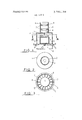
- FIG. 1 is a vertical section through the mechanical part of the machine
- FIG. 2 is a plan view of the machine shown in FIG.
- FIG. 3 is a horizontal section taken at IIIIII of FIG.
- FIG. 4 is a circuit diagram of a photocell and detector circuit
- FIG. 5 is a block schematic diagram of the counter, dust level detector, overspeed warning and selfchecking arrangements
- FIG. 6 shows detail circuitry of the counter, dust level detector and overspeed warning arrangements
- FIG. 7 shows detail circuitry of the self checking arrangement.
- the machine shown in FIG. 1, 2 and 3 for counting tablets, pills or capsules comprises a vertically disposed, cylindrical casing 1 of circular cross-section and a vertically disposed, cylindrical inlet passage 2, also of circular cross-section, mounted coaxially on top of the casing.
- a series of spaced annuli 3 are secured to the internal wall of the passage and have upper surfaces 4 which taper downwardly and inwardly.
- annular passage 6 is defined between the periphery of the base of the cone 5 and the internal wall of the casing 1 and is divided into open-bottomed compartments 7 by a series of radial partitions 8.
- a photocell 9 is mounted just below the bottom of each compartment 7 adjacent the wall of the casing 1 and a single light source 10 for all the photocells 9 is mounted on the axis of the casing l in substantially the same horizontal plane as the photocells 9.
- the light source is powered by a smoothed D. C. supply.
- a collecting chamber 11 and drawer 12 are provided at the bottom of the machine.
- tablets to be counted enter the top of the inlet passage 2 and fall downwardly into the casing 1.
- the tapered annuli 3 in the inlet passage 2 serve to break up any bunched group of tablets to provide an even flow of tablets and also to concentrate the flow of tablets along vertical axis of the casing l.
- the tablets enter the casing 1 and strike the cone 5 at or adjacent its apex to be dispersed outwardly into the compartments 7 around the outside of the cone 5.
- the tablets fall through the compartments 7, are detected by the photocells 9 and finally pass into the collecting chamber 11 and drawer 12.
- each photocell 9 is included in a separate detecting circuit which also includes an amplifying circuit (based on transistor T,) which amplifies the photocell output, a trigger circuit (based on transistors T and T which triggers with each falling ball of current caused by modulation of the light on the photocell, resulting from the passage ofa tablet, and a differentiating circuit (based on transistor 1",) which differentiates each trigger pulse to provide a short duration impulse (approximately 2 microseconds).
- These impulses are fed via a diode D2 and in parallel with impulses from the other detecting circuits to a suitably fast counting circuit shown in FIG. 5.
- the output of the counting circuit feeds circuits for numeral indicator tubes which digitally display the number of tablets counted.
- the outputs of the sixteen detector circuits pass through respective diodes to line 20, through a NOR gate 21 to the counter 22.
- the output of counter 22 is fed to a decoder and drive unit 23 for displaying the count on numerical indicator tubes.
- the machine is intended to be cleaned regularly to avoid the photoelectric ells and the lamp from becoming obscured by dust from, for example, uncoated tablets.
- the output of one of the photocells is taken on line 24 to a clamp circuit 25.
- clamp circuit 25 there is a voltage reference didode in series with the photocell output voltage.
- the reference voltage current is passed to the base of transistor T so that this transistor becomes conductive and clamps line 20 so that the impulses from the counting circuits are unable to reach the counter.
- the dust level exceeds a predetermined value the counter is inhibited.
- a signal is passed from clamp 25 to a latch 26 which becomes conductive and operates a warning lamp 27 to give warning that counting has stopped as a result of a high dust level.
- a warning circuit is also provided which indicates if a predetermined count rate representing themaximum accurate working throughput of the machine, is exceeded.
- the warning circuit comprises an oscillator 28, the output of which passes through a pulse sharpener 29 and a gate 30 to a counter timer 31. When the counted pulses from the oscillator reaches a predetermined count an output is provided on line 32 to a second input of the gate 30 and thus the further count of pulses is inhibited. By this means, a time interval is provided with corresponds to a predetermined count of oscillator pulses.
- the warning circuit also comprises a gate 33 which takes inputs from the units and tens counters of counter 22 and provides an output at certain counts (e.g. 18, 38, 58, 78 and 98).
- Each output of gate 33 provides a start signal which resets counter timer 31 to zero so that a counting interval can commence.
- the start signal also passes to a differentiator 34 so that sharp pulses are provided at the input of a gate 35.
- Gate 35 has a second input which receives a pulse from counter timer 31 corresponding with the end of the timed period. If the timing period had not expired before the start signal at the output of gate 33 reoccurs (due to excessive speed of count) then gate 35 provides an output which trips a bistable circuit 36, thus providing a signal which activates an overspeed indicator 37 and which also passes to gate 21 and thereby inhibits the further counting of tablets. Provided that the timed period expires before the occurrence of the next start signal from gate 33 no overspeed indication is given and the gate 21 is not inhibited.
- the apparatus has sixteen separate photocells and detecting circuits and it is important that the apparatus should be rendered inoperative if any one or more of the detecting circuits becomes faulty.
- a self checking circuit is therefore provided by making the machine check itself every time the reset button 38 is pressed and released.
- the gate 359 provides an output which is fed into the circuit 40 which produces a pulse of about 8 milliseconds duration. This pulse is fed to a transistor switch 41 which reduces the power supplied to lamp so that a count of sixteen should be produced in counter 22, i.e. a count from each photocell, the counter 22 having already been set to zero by the output of gate 39 passing to gate 42 to given an output at reset A.
- Bistable circuit 36 is also reset by the output of gate 39.
- a gate 43 having eight inputs is connected to the counter so that a count of 16 there is a signal on each of the eight inputs.
- a charge of output is fed to a gate 44.
- pulse sharpener 45 At the end of the lamp dipping pulse from the circuit 40, a pulse is produced by pulse sharpener 45 which after being delayed in delay circuit 46 provides a strobe pulse STR.
- This strobe pulse is passed to gate 44 and if the count of 16 is not indicated on the other input of gate 44 then an output is provided on line 47 showing that the selfchecking has failed.
- Monostable circuit 48 provides that the fail signal is given a predetermined duration.
- This fail signal is passed to a second input of gate 39 so that gate 39 gives an output corresponding to that of pressing the reset button so that the rechecking opera tion is repeated until such times that a satisfactory count is obtained. If the right answer never comes, the machine will be found to be unusable by the operator because it will be totally occupied in this self checking operation. When a satisfactory check is obtained the machine becomes usable and so that the tablet count should commence from zero the strobe pulse output of delay circuit 46 passes to a further delay circuit 49 before passing to gate 42 which causes a reset pulse on reset A, thus reseting the counter to zero.
- FIGS. 5 and 6 show detail of the circuitry in the various blocks of FIG. 5, the various sections of the circuit being identified by similar reference numerals.
- a machine for counting small, discrete articles comprising a cone having a vertical axis with its apex upwardly directed for dispersing a flow of articles to be counted into separate falling streams, said streams being divided by vertical partitions radially arranged in an annular space around the base of the cone, means for feeding a substantially even flow of articles to the dispersing means comprising a plurality of spaced annuli having upper surfaces which taper downwardly and inwardly, the annuli being arranged one above another and all above the cone on an axis substantially coinciding with the axis of the cone, a plurality of detectors individually associated with each stream for detecting each article in each falling stream, and counting means fed by the outputs from all of the detectors for counting the total number of articles in all of the streams.
- the detecting means for each stream includes a photocell, the photocells being arranged on a circle about a central illuminating lamp so that articles passing down each stream interrupt the path of light from the lamp to the respective photocell.
- a machine for counting small, discrete articles comprising a cone having a vertical axis with its apex upwardly directed for dispersing a flow of articles to be counted into separate falling streams, means for feeding a substantialy even flow of articles to the dispersing means, a plurality of detectors individually associated with each stream for detecting each article in each falling stream, counting means fed by the outputs from all of the detectors for counting the total number of articles in all of the streams, means responsive to said counting for determining the article counting rate, and a warning system responsive to said means for determining for issuing a warning when a predetermined article counting rate of the machine is exceeded.
- warning system also inhibits the continued counting of the machine when the predetermined throughput is exceeded and until the machine is reset.
- timer means comprises a pulse generator and a counter which counts the pulses to a predetermined number to establish the predetermined interval of time.
- a machine as claimed in claim 3, wherein the satisfactory operation of all the article detectors is obtained by simulating the passing of an article at each detector and recording that the total count of the counting means corresponds with the number of detectors.
- photocells being arranged on a circle about a central illuminating lamp so that articles passing down each stream interrupt the path of light from the lamp to the respective photocell, and wherein the simulation is provided by dimming the lamp once.
Landscapes
- Physics & Mathematics (AREA)
- General Physics & Mathematics (AREA)
- Engineering & Computer Science (AREA)
- Theoretical Computer Science (AREA)
- Basic Packing Technique (AREA)
- Medical Preparation Storing Or Oral Administration Devices (AREA)
- Emergency Alarm Devices (AREA)
Abstract
Description
Claims (9)
Applications Claiming Priority (1)
| Application Number | Priority Date | Filing Date | Title |
|---|---|---|---|
| GB4286770A GB1358378A (en) | 1970-09-08 | 1970-09-08 | Counting machines |
Publications (1)
| Publication Number | Publication Date |
|---|---|
| US3789194A true US3789194A (en) | 1974-01-29 |
Family
ID=10426311
Family Applications (1)
| Application Number | Title | Priority Date | Filing Date |
|---|---|---|---|
| US00178571A Expired - Lifetime US3789194A (en) | 1970-09-08 | 1971-09-08 | Relating to counting machines |
Country Status (3)
| Country | Link |
|---|---|
| US (1) | US3789194A (en) |
| DE (1) | DE2144719A1 (en) |
| GB (1) | GB1358378A (en) |
Cited By (14)
| Publication number | Priority date | Publication date | Assignee | Title |
|---|---|---|---|---|
| US3900718A (en) * | 1973-12-26 | 1975-08-19 | Harold H Seward | System for counting pills and the like |
| US3928753A (en) * | 1974-01-22 | 1975-12-23 | Engineering Dev Associates Inc | Small object counting apparatus |
| US3983373A (en) * | 1975-04-30 | 1976-09-28 | Columbine Glass Company, Inc. | Article control system |
| US4012622A (en) * | 1972-04-20 | 1977-03-15 | Standard Pressed Steel Co. | Method and apparatus for counting small parts |
| US4027143A (en) * | 1974-12-17 | 1977-05-31 | Witriol Norman M | Encoding altimeter |
| US4396828A (en) * | 1980-09-26 | 1983-08-02 | Programs & Analysis, Inc. | Pill counter |
| US4611124A (en) * | 1984-06-13 | 1986-09-09 | The United States Of America As Represented By The Secretary Of The Air Force | Fly's eye sensor nonlinear signal processing |
| US5317645A (en) * | 1991-02-28 | 1994-05-31 | Kirby Lester Inc. | Method and apparatus for the recognition and counting of discrete objects |
| US5774518A (en) * | 1997-01-30 | 1998-06-30 | Kirby; John | Discrete tablet counting machine |
| US6631826B2 (en) | 2001-07-20 | 2003-10-14 | Parata Systems, Llc | Device to count and dispense articles |
| US20110085634A1 (en) * | 2008-04-10 | 2011-04-14 | Riny Bay Sportswear | Apparatus for Counting and Displaying and the Use Thereof |
| US8213014B1 (en) | 2007-07-21 | 2012-07-03 | Werner Willemse | High speed counter and inspector for medicament and other small objects |
| US8271128B1 (en) | 2008-07-30 | 2012-09-18 | Kirby Lester, Llc | Pharmacy workflow management system including plural counters |
| US9977871B2 (en) | 2014-01-14 | 2018-05-22 | Capsa Solutions Llc | Cassette control including presence sensing and verification |
Families Citing this family (1)
| Publication number | Priority date | Publication date | Assignee | Title |
|---|---|---|---|---|
| US4597091A (en) * | 1982-09-07 | 1986-06-24 | Blake David J | Pill counter |
Citations (2)
| Publication number | Priority date | Publication date | Assignee | Title |
|---|---|---|---|---|
| US1047316A (en) * | 1912-04-15 | 1912-12-17 | Louis T Sicka | Ore feed-mixer and distributer. |
| US2632588A (en) * | 1952-01-30 | 1953-03-24 | Jr John Hoar | Counting and packaging apparatus |
-
1970
- 1970-09-08 GB GB4286770A patent/GB1358378A/en not_active Expired
-
1971
- 1971-09-07 DE DE19712144719 patent/DE2144719A1/de active Pending
- 1971-09-08 US US00178571A patent/US3789194A/en not_active Expired - Lifetime
Patent Citations (2)
| Publication number | Priority date | Publication date | Assignee | Title |
|---|---|---|---|---|
| US1047316A (en) * | 1912-04-15 | 1912-12-17 | Louis T Sicka | Ore feed-mixer and distributer. |
| US2632588A (en) * | 1952-01-30 | 1953-03-24 | Jr John Hoar | Counting and packaging apparatus |
Cited By (18)
| Publication number | Priority date | Publication date | Assignee | Title |
|---|---|---|---|---|
| US4012622A (en) * | 1972-04-20 | 1977-03-15 | Standard Pressed Steel Co. | Method and apparatus for counting small parts |
| US3900718A (en) * | 1973-12-26 | 1975-08-19 | Harold H Seward | System for counting pills and the like |
| US3928753A (en) * | 1974-01-22 | 1975-12-23 | Engineering Dev Associates Inc | Small object counting apparatus |
| US4027143A (en) * | 1974-12-17 | 1977-05-31 | Witriol Norman M | Encoding altimeter |
| US3983373A (en) * | 1975-04-30 | 1976-09-28 | Columbine Glass Company, Inc. | Article control system |
| US4396828A (en) * | 1980-09-26 | 1983-08-02 | Programs & Analysis, Inc. | Pill counter |
| US4611124A (en) * | 1984-06-13 | 1986-09-09 | The United States Of America As Represented By The Secretary Of The Air Force | Fly's eye sensor nonlinear signal processing |
| US5317645A (en) * | 1991-02-28 | 1994-05-31 | Kirby Lester Inc. | Method and apparatus for the recognition and counting of discrete objects |
| US5774518A (en) * | 1997-01-30 | 1998-06-30 | Kirby; John | Discrete tablet counting machine |
| GB2321740A (en) * | 1997-01-30 | 1998-08-05 | John Kirby | Discrete tablet counting machine |
| US6631826B2 (en) | 2001-07-20 | 2003-10-14 | Parata Systems, Llc | Device to count and dispense articles |
| US20040159669A1 (en) * | 2001-07-20 | 2004-08-19 | Jasper Pollard | Device to count and dispense articles |
| US8651326B2 (en) | 2001-07-20 | 2014-02-18 | Parata Systems, Llc | Device to count and dispense articles |
| US8213014B1 (en) | 2007-07-21 | 2012-07-03 | Werner Willemse | High speed counter and inspector for medicament and other small objects |
| US20110085634A1 (en) * | 2008-04-10 | 2011-04-14 | Riny Bay Sportswear | Apparatus for Counting and Displaying and the Use Thereof |
| US8271128B1 (en) | 2008-07-30 | 2012-09-18 | Kirby Lester, Llc | Pharmacy workflow management system including plural counters |
| US8855811B1 (en) | 2008-07-30 | 2014-10-07 | Kirby Lester, Llc | Pharmacy workflow management system including plural counters |
| US9977871B2 (en) | 2014-01-14 | 2018-05-22 | Capsa Solutions Llc | Cassette control including presence sensing and verification |
Also Published As
| Publication number | Publication date |
|---|---|
| DE2144719A1 (en) | 1972-03-23 |
| GB1358378A (en) | 1974-07-03 |
Similar Documents
| Publication | Publication Date | Title |
|---|---|---|
| US3789194A (en) | Relating to counting machines | |
| CN105836226B (en) | A kind of cillin bottle appearance and size detection arrangement are started going to a nursery machine | |
| US4120403A (en) | Photoelectric apparatus for sorting variegated articles according to size | |
| CN207271654U (en) | A kind of fully automatic high-speed light splitting machine | |
| ES382931A1 (en) | Apparatus and method for detecting and reporting ends down on textile machines | |
| US3928753A (en) | Small object counting apparatus | |
| US3638191A (en) | Production monitoring system | |
| GB1391221A (en) | Electronic system and method for capsule inspection | |
| US3754558A (en) | Coin processing apparatus with jam detection system | |
| US4694964A (en) | Device for conveying components particularly integrated chips, from an input magazine to an output magazine | |
| US3510632A (en) | Digital stretch and speed indicating apparatus | |
| US4455549A (en) | Indication device | |
| US4344582A (en) | Microprocessor-controlled product roving system | |
| US3786265A (en) | Apparatus for detecting defects in continuous traveling material | |
| JPS6127492B2 (en) | ||
| CN103447246B (en) | High-speed full-automatic capsule vision detector | |
| US3690123A (en) | Device for the automatic measurement of the length of yarn consumed in knitting machines | |
| US4496055A (en) | Apparatus for forming groups of cigarettes | |
| US4241293A (en) | Scanner for detecting and indicating missing and wedged articles in slat-type counting machine | |
| CN109422071A (en) | A kind of LED light production transport device with tally function | |
| US5774518A (en) | Discrete tablet counting machine | |
| GB1385290A (en) | Measuring instrument | |
| GB2108818A (en) | Apparatus for testing cigarettes in groups | |
| US3772916A (en) | Variable increment transducer for fluid flow metering systems | |
| CN219162397U (en) | Device for detecting falling off of ejector plate of grain counting machine |
Legal Events
| Date | Code | Title | Description |
|---|---|---|---|
| AS | Assignment |
Owner name: KIRBY LESTER INCORPORATED, 1111 POST ROAD RIVERSID Free format text: ASSIGNMENT OF ASSIGNORS INTEREST.;ASSIGNOR:KIRBY LESTER (ELECTRONICS ) LIMITED, A CORP. OF ENGLAND;REEL/FRAME:003946/0347 Effective date: 19811109 |
|
| STCF | Information on status: patent grant |
Free format text: PATENTED FILE - (OLD CASE ADDED FOR FILE TRACKING PURPOSES) |
|
| AS | Assignment |
Owner name: SILVER POINT FINANCE, LLC, AS AGENT, CONNECTICUT Free format text: SECURITY AGREEMENT;ASSIGNOR:KIRBY LESTER, LLC;REEL/FRAME:019580/0088 Effective date: 20070711 Owner name: SILVER POINT FINANCE, LLC, AS AGENT,CONNECTICUT Free format text: SECURITY AGREEMENT;ASSIGNOR:KIRBY LESTER, LLC;REEL/FRAME:019580/0088 Effective date: 20070711 |
|
| AS | Assignment |
Owner name: SILVER POINT FINANCE, LLC, AS AGENT, CONNECTICUT Free format text: CORRECTIVE ASSIGNMENT TO REMOVE INCORRECT 7,080,755, 6,555,251, 5,463,839, 3,760,887 PATENT AND APPLICATIONS 11/550,361, 11/484983, 11/474239, 11/445,105, 11/445,408, 11/056,521, 11/108,374, 11/072,887, 10/939,620, 10/025,401 AS NOTED BELOW WHICH WERE RECORDED ON REEL 019580 FRAME 0088;ASSIGNOR:KIRBY LESTER, LLC;REEL/FRAME:025812/0709 Effective date: 20070711 |
|
| AS | Assignment |
Owner name: THE PRIVATEBANK AND TRUST COMPANY, AS ADMINISTRATI Free format text: SECOND AMENDED AND RESTATED PATENT AND TRADEMARK SECURITY AGREEMENT;ASSIGNORS:CAPSA SOLUTIONS LLC (F/K/A INTERNATIONAL RETAIL SERVICES GROUP, LLC);CAPSA INTERNATIONAL SALES CORPORATION;KIRBY LESTER, LLC;AND OTHERS;REEL/FRAME:033280/0164 Effective date: 20140701 |
|
| AS | Assignment |
Owner name: THE PRIVATEBANK AND TRUST COMPANY, AS ADMINISTRATIVE AGENT, ILLINOIS Free format text: REAFFIRMATION OF AND FIRST AMENDMENT TO SECOND AMENDED AND RESTATED PATENT AND TRADEMARK SECURITY AGREEMENT;ASSIGNORS:CAPSA SOLUTIONS LLC (F/K/A INTERNATIONAL RETAIL SERVICES GROUP, LLC);CAPSA INTERNATIONAL SALES CORPORATION;IRSG HOLDINGS, LLC;REEL/FRAME:036337/0946 Effective date: 20150806 Owner name: THE PRIVATEBANK AND TRUST COMPANY, AS ADMINISTRATI Free format text: REAFFIRMATION OF AND FIRST AMENDMENT TO SECOND AMENDED AND RESTATED PATENT AND TRADEMARK SECURITY AGREEMENT;ASSIGNORS:CAPSA SOLUTIONS LLC (F/K/A INTERNATIONAL RETAIL SERVICES GROUP, LLC);CAPSA INTERNATIONAL SALES CORPORATION;IRSG HOLDINGS, LLC;REEL/FRAME:036337/0946 Effective date: 20150806 |
|
| AS | Assignment |
Owner name: CAPSA SOLUTIONS LLC, OREGON Free format text: RELEASE BY SECURED PARTY;ASSIGNOR:THE PRIVATEBANK AND TRUST COMPANY, AS ADMINISTRATIVE AGENT;REEL/FRAME:043814/0565 Effective date: 20170908 |