US378643A - M aemington - Google Patents
M aemington Download PDFInfo
- Publication number
- US378643A US378643A US378643DA US378643A US 378643 A US378643 A US 378643A US 378643D A US378643D A US 378643DA US 378643 A US378643 A US 378643A
- Authority
- US
- United States
- Prior art keywords
- engine
- valve
- steam
- cylinders
- port
- Prior art date
- Legal status (The legal status is an assumption and is not a legal conclusion. Google has not performed a legal analysis and makes no representation as to the accuracy of the status listed.)
- Expired - Lifetime
Links
- 241001052209 Cylinder Species 0.000 description 2
- LTMHDMANZUZIPE-PUGKRICDSA-N Digoxin Chemical compound C1[C@H](O)[C@H](O)[C@@H](C)O[C@H]1O[C@@H]1[C@@H](C)O[C@@H](O[C@@H]2[C@H](O[C@@H](O[C@@H]3C[C@@H]4[C@]([C@@H]5[C@H]([C@]6(CC[C@@H]([C@@]6(C)[C@H](O)C5)C=5COC(=O)C=5)O)CC4)(C)CC3)C[C@@H]2O)C)C[C@@H]1O LTMHDMANZUZIPE-PUGKRICDSA-N 0.000 description 2
- 241000220010 Rhode Species 0.000 description 2
- 210000000038 chest Anatomy 0.000 description 2
- 235000013531 gin Nutrition 0.000 description 2
- RZVAJINKPMORJF-UHFFFAOYSA-N p-acetaminophenol Chemical compound CC(=O)NC1=CC=C(O)C=C1 RZVAJINKPMORJF-UHFFFAOYSA-N 0.000 description 2
- 239000004576 sand Substances 0.000 description 2
Images

Classifications
-
- F—MECHANICAL ENGINEERING; LIGHTING; HEATING; WEAPONS; BLASTING
- F01—MACHINES OR ENGINES IN GENERAL; ENGINE PLANTS IN GENERAL; STEAM ENGINES
- F01B—MACHINES OR ENGINES, IN GENERAL OR OF POSITIVE-DISPLACEMENT TYPE, e.g. STEAM ENGINES
- F01B1/00—Reciprocating-piston machines or engines characterised by number or relative disposition of cylinders or by being built-up from separate cylinder-crankcase elements
- F01B1/06—Reciprocating-piston machines or engines characterised by number or relative disposition of cylinders or by being built-up from separate cylinder-crankcase elements with cylinders in star or fan arrangement
- F01B1/0603—Reciprocating-piston machines or engines characterised by number or relative disposition of cylinders or by being built-up from separate cylinder-crankcase elements with cylinders in star or fan arrangement the connection of the pistons with an element being at the outer ends of the cylinders
- F01B1/0606—Reciprocating-piston machines or engines characterised by number or relative disposition of cylinders or by being built-up from separate cylinder-crankcase elements with cylinders in star or fan arrangement the connection of the pistons with an element being at the outer ends of the cylinders with cam-actuated distribution member(s)
-
- F—MECHANICAL ENGINEERING; LIGHTING; HEATING; WEAPONS; BLASTING
- F03—MACHINES OR ENGINES FOR LIQUIDS; WIND, SPRING, OR WEIGHT MOTORS; PRODUCING MECHANICAL POWER OR A REACTIVE PROPULSIVE THRUST, NOT OTHERWISE PROVIDED FOR
- F03C—POSITIVE-DISPLACEMENT ENGINES DRIVEN BY LIQUIDS
- F03C1/00—Reciprocating-piston liquid engines
- F03C1/02—Reciprocating-piston liquid engines with multiple-cylinders, characterised by the number or arrangement of cylinders
Definitions
- This invention relates to steam-engines, and has for its object to produce asmall, compact, and eflicient engine, which is especially designed, among other things, to be used on board ships for running dynamomachines.
- I have constructed an engine say of one hundred horse-powerin which a main shaft is provided with two cranks set substantially opposite, the said cranks havingjoined to them con necting rods and pistons reciprocating in cyl inders between which is located a valvechest containing two independent valve chambers or cylinders, in which are reciprocated twoindependent valves-one for each cylindermy improved engine being herein shown as a horizontal engine.
- the valves referred to are arranged within their chambers, as will be described, so that they admit steam to their respective cylinders simultaneously, thus producing two independent steam engines-say of fifty horse-power eachthe said independent valves being controlled by a single governor of any type, such as now commonly used, or it may be an eccentric.
- Figure 1 is a plan or top view of a horizontal engine constructed in accordance with my invention
- Fig. 2 a side view of the same, the steam-inlet pipe being shown broken off Fig. 3, an end view of Figs. 1 and 2;
- Figs. sand 5 an end view of Figs. 1 and 2;
- the bed or base A designed to rest upon the floor or a suitable floundation laid thereon, has ported or otherwise secured to it two cylinders, A A and a valve-chest, A, preferably located between the said cylinders, the said valve-chest and cylinders being preferably cast in one piece.
- the base A supports in suitable bearings a main shaft, 0, provided with cranks a a set substantially opposite, the said cranks having joined to them connecting rods a a respectively, secured to cross-heads a a, reciprocating in guides a a fastened to the base A.
- the cross-heads a a have connected to them the pistonrods b b of pistons b" b, (see Fig. 41,) reciprocating in the cylinders A A respectively.
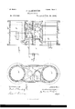
- the cylinder A is provided at its opposite ends, as shown in Fig. 4, with ports b If and the cylinder A" with ports b F.
- valve-chest A between the cylinders A A contains within it two independent valve chambers or cylinders, c c, the valvecylinder 0 being shown as divided atits center to form a steam-inlet port, 0", and provided at its opposite ends with eXhaustports c c.
- the valvecylinder 0 is shown with its exhaust-port at the center and steanrinlet ports at its ends.
- valve-cylinders c 0 contain, as herein shown, Valve-pistons c 0 having their valve stems or rods 0 0 extended beyond the valvechest and connected to a cross-bar, 0 to which is secured one end of a link, (Z, the other end of said link being connected, as shown, to a rocker-arm, d, (see Fig. 1,) on a shaft, d", having bearings in the base A and extended to one side of the engine, where it is provided, as shown, with a rocker-arm, d (see Fig.
- valves 0 0 herein shown are substantially such as shown in my United States Patent No. 244,160, dated July 12, 1881, the said valves having near their opposite ends annular openings 6 6, connected to one another by a longitudinal passage or passages through the middle portion of the valve.
- Fig. 4- it will be seen that live steam is being admitted into the port 6 leading to the engine-cylinder A, from both ends of the valve 6 at the same time, as indicated by arrows 20, while the steam in the engine-cylinder A is permitted to exhaust through the port 1) into the exhaust-port c of the valve chest 0, as indicated by arrow 23.
- Live steam is being admitted to the engine-cylinder A from both ends of the valve 0 as indicated by arrows 21, while the steam in the cylinder A" is permitted to pass through the port 12 into the exhaust, as indicated by arrow 22.
- the exhaust-ports c c of the valve-cylinder c and the exhaust-port c of the valve cylinder 0 communicate with a common exhaust, e (See Figs. 2 and 3.)
- My improved engine--say of one hundred 5 h.orse*power is small and compact, and occupies'but little more space than an engine of but fifty horse-power, so that it may be used, among other things, for running dynamo-machines on board ships, where heretofore the objection to the use of dynamos has been the great space required for the engine and dynamo.
- the dynamo may be placed, if desired, alongside the engine and coupled to it in any suitable manner, thus requiring but a substantially small room.
- I claim 1 In a steam-engine, two engine-cylinders, two valve chambers or cylinders communicating therewith, one of said valve cylinders having a steam-inlet port at its ends and an exhaust-port near its center, the other valvecylinder having an exhaust-port at its ends and a steam-inlet near its center, and a valve in each cylinder, combined with a governor operatively connected to the said valves to operate them, substantially as described.
- a steamengine two engine-cylinders, A Aitwo valve cylinders intermediate of and communicating with the said engine-cylinders, one of said valve-cylinders having a steaminletport at its ends and an exhaust-port near its center, the other valve-cylinder having an exhaust-port at its ends and a steam-inlet near its center, and a piston-valve in each cylinder, combined with a governor operatively connected to the said piston-valves, to operate them substantially as described.
Description
2 Shets-Sheet 11.
(No Model.)
P. ARMINGTON.
STEAM ENGINE.
No. 378,643. Patented Feb. 28, 1888 Aha/45 (No Model.) 2 Sheets-Sheet2.
P. ARMINGTON.
I STEAM ENGINE. No. 378,643. Patented Feb. 28, 1888 lllnirisn S'rn'rns PATENT tries.
PARDON ARMINGTON, OF PROVIDENCE, RHODE ISLAND.
STEA ENGINE.
SPECIFICATION Eorming part of Letters Patent No. 378,643, dated February 28, 1888.
Application filed May 13, 1887. Serial No. 238,088.
(No model.)
To all whom it may concern.-
Be it known that I, PARDON ARMINGTON, of Providence, county of Providence, and State of Rhode Island, have invented an improvement in SteainEngines, of which the follow ing description, in connection with the accompanying drawings, is a specification, like letters on the drawings representing like parts.
This invention relates to steam-engines, and has for its object to produce asmall, compact, and eflicient engine, which is especially designed, among other things, to be used on board ships for running dynamomachines.
It has been a long-soughti'or desideratumto provide an engine of a given horse-powersuch, forinstance, as a hundred horse-power which shall be considerably smaller than en gines as now constructed having the same horse-power, so that a considerable saving in space may be effected. Thisisespecially true when applied to ships, whereon space is an important factor.
In accordance with my invention I have constructed an engine say of one hundred horse-powerin which a main shaft is provided with two cranks set substantially opposite, the said cranks havingjoined to them con necting rods and pistons reciprocating in cyl inders between which is located a valvechest containing two independent valve chambers or cylinders, in which are reciprocated twoindependent valves-one for each cylindermy improved engine being herein shown as a horizontal engine. The valves referred to are arranged within their chambers, as will be described, so that they admit steam to their respective cylinders simultaneously, thus producing two independent steam engines-say of fifty horse-power eachthe said independent valves being controlled by a single governor of any type, such as now commonly used, or it may be an eccentric.
The particular features of my invention will be pointed out in the claims at the end of this specification.
Figure 1 is a plan or top view of a horizontal engine constructed in accordance with my invention; Fig. 2, a side view of the same, the steam-inlet pipe being shown broken off Fig. 3, an end view of Figs. 1 and 2; Figs. sand 5,
sectional views, on an enlarged scale, of the enginecylinders and the aalve-chest between them.
The bed or base A, designed to rest upon the floor or a suitable floundation laid thereon, has ported or otherwise secured to it two cylinders, A A and a valve-chest, A, preferably located between the said cylinders, the said valve-chest and cylinders being preferably cast in one piece. The base A supports in suitable bearings a main shaft, 0, provided with cranks a a set substantially opposite, the said cranks having joined to them connecting rods a a respectively, secured to cross-heads a a, reciprocating in guides a a fastened to the base A. The cross-heads a a have connected to them the pistonrods b b of pistons b" b, (see Fig. 41,) reciprocating in the cylinders A A respectively.
The cylinder A is provided at its opposite ends, as shown in Fig. 4, with ports b If and the cylinder A" with ports b F.
The valve-chest A between the cylinders A A contains within it two independent valve chambers or cylinders, c c, the valvecylinder 0 being shown as divided atits center to form a steam-inlet port, 0", and provided at its opposite ends with eXhaustports c c. The valvecylinder 0 is shown with its exhaust-port at the center and steanrinlet ports at its ends.
The valve-cylinders c 0 contain, as herein shown, Valve-pistons c 0 having their valve stems or rods 0 0 extended beyond the valvechest and connected to a cross-bar, 0 to which is secured one end of a link, (Z, the other end of said link being connected, as shown, to a rocker-arm, d, (see Fig. 1,) on a shaft, d", having bearings in the base A and extended to one side of the engine, where it is provided, as shown, with a rocker-arm, d (see Fig. 1,) which is connected to an eccentric-rod, cl, of an eccentric, cl, on the main shaft a, the said eccentric forming part of a governor sub stantially such as shown and described in my United States Patent No. 247,527, granted to me September 27, 1881; butinstead of the governor shown I may employ any other wellknown type of governor, such as now commonly used.
The valves 0 0 herein shown are substantially such as shown in my United States Patent No. 244,160, dated July 12, 1881, the said valves having near their opposite ends annular openings 6 6, connected to one another by a longitudinal passage or passages through the middle portion of the valve.
Steam is admitted to the valvechest th rough the pipe 6", provided with a throttle-valve adapted to be operated, as shown, by the wheel .6, the said pipe communicating with the port or opening 0 in the valve-chest. (See Fig. 5.)
In the operation of my improved engine, as shown in the drawings, the piston b is about to commence its upstroke while the piston b is about to begin its downstroke. It will be noticed that both pistons are acted upon by live steam at the same time, although moving in opposite directions. This result is effected by arranging the steam inlet and exhaust ports of the valve-cylinders as described.
Referring to Fig. 4-, it will be seen that live steam is being admitted into the port 6 leading to the engine-cylinder A, from both ends of the valve 6 at the same time, as indicated by arrows 20, while the steam in the engine-cylinder A is permitted to exhaust through the port 1) into the exhaust-port c of the valve chest 0, as indicated by arrow 23. Live steam is being admitted to the engine-cylinder A from both ends of the valve 0 as indicated by arrows 21, while the steam in the cylinder A" is permitted to pass through the port 12 into the exhaust, as indicated by arrow 22. The exhaust-ports c c of the valve-cylinder c and the exhaust-port c of the valve cylinder 0 communicate with a common exhaust, e (See Figs. 2 and 3.)
It will be seen that my improved engine is composed of two independent double-acting engines, each of a given capacityfor instance, fifty horse powerthe said engines being coupled together, as described, to produce an engine of double the capacity-that is, of one hundred horse-power.
My improved engine--say of one hundred 5 h.orse*poweris small and compact, and occupies'but little more space than an engine of but fifty horse-power, so that it may be used, among other things, for running dynamo-machines on board ships, where heretofore the objection to the use of dynamos has been the great space required for the engine and dynamo.
With an engine constructed as above described the dynamo may be placed, if desired, alongside the engine and coupled to it in any suitable manner, thus requiring but a substantially small room.
I claim 1. In a steam-engine, two engine-cylinders, two valve chambers or cylinders communicating therewith, one of said valve cylinders having a steam-inlet port at its ends and an exhaust-port near its center, the other valvecylinder having an exhaust-port at its ends and a steam-inlet near its center, and a valve in each cylinder, combined with a governor operatively connected to the said valves to operate them, substantially as described.
2. In a steamengine, two engine-cylinders, A Aitwo valve cylinders intermediate of and communicating with the said engine-cylinders, one of said valve-cylinders having a steaminletport at its ends and an exhaust-port near its center, the other valve-cylinder having an exhaust-port at its ends and a steam-inlet near its center, and a piston-valve in each cylinder, combined with a governor operatively connected to the said piston-valves, to operate them substantially as described.
In testimony whereof I have signed my name to this specification in the presence of two subscribing witnesses.
PARDON ARMINGTON.
\Vitnesses:
J. H. CHURCHILL, B. DEWAR.
Publications (1)
| Publication Number | Publication Date |
|---|---|
| US378643A true US378643A (en) | 1888-02-28 |
Family
ID=2447642
Family Applications (1)
| Application Number | Title | Priority Date | Filing Date |
|---|---|---|---|
| US378643D Expired - Lifetime US378643A (en) | M aemington |
Country Status (1)
| Country | Link |
|---|---|
| US (1) | US378643A (en) |
-
0
- US US378643D patent/US378643A/en not_active Expired - Lifetime
Similar Documents
| Publication | Publication Date | Title |
|---|---|---|
| US378643A (en) | M aemington | |
| US391941A (en) | brown | |
| US812199A (en) | Compound steam-engine. | |
| US514747A (en) | brown | |
| US405208A (en) | gardner | |
| US544476A (en) | Half to dorr b | |
| US393461A (en) | David donald | |
| US358845A (en) | Steam engine | |
| US289648A (en) | Pumping engine | |
| US447671A (en) | eickershqff | |
| US604109A (en) | The norris peters co | |
| US459151A (en) | Valve for steam-engines | |
| US194034A (en) | Improvement in steam-engines | |
| US678709A (en) | Semicompound telescopic engine. | |
| US570054A (en) | Duplex steam-engine | |
| US241093A (en) | Compound steam-engine | |
| US477234A (en) | Steam-engine | |
| US763502A (en) | Valve-gear. | |
| US406012A (en) | Valve for compound engines | |
| US206558A (en) | Improvement in valve-actions of duplex engines and pumps | |
| US406607A (en) | Steam-engine | |
| US313366A (en) | Compound steam engine | |
| US321325A (en) | hodges | |
| US427231A (en) | graft-on | |
| US329987A (en) | willans |