US3785176A - Thread supply apparatus for textile machinery, particularly circular knitting machines - Google Patents
Thread supply apparatus for textile machinery, particularly circular knitting machines Download PDFInfo
- Publication number
- US3785176A US3785176A US00262409A US3785176DA US3785176A US 3785176 A US3785176 A US 3785176A US 00262409 A US00262409 A US 00262409A US 3785176D A US3785176D A US 3785176DA US 3785176 A US3785176 A US 3785176A
- Authority
- US
- United States
- Prior art keywords
- thread supply
- belts
- machine
- rod
- thread
- Prior art date
- Legal status (The legal status is an assumption and is not a legal conclusion. Google has not performed a legal analysis and makes no representation as to the accuracy of the status listed.)
- Expired - Lifetime
Links
Images


Classifications
-
- D—TEXTILES; PAPER
- D04—BRAIDING; LACE-MAKING; KNITTING; TRIMMINGS; NON-WOVEN FABRICS
- D04B—KNITTING
- D04B15/00—Details of, or auxiliary devices incorporated in, weft knitting machines, restricted to machines of this kind
- D04B15/38—Devices for supplying, feeding, or guiding threads to needles
- D04B15/48—Thread-feeding devices
Definitions
- the arms carry projecting rods which extend at right angles to the planes in which drive belts are continuously driven from the machine, to permit selective vertical adjustment of thread supply apparatus to be engaged by selected ones of the drive belts.
- the arms carry two vertical rods, one for idler pulleys around which the drive belts can be looped and the other for the thread supply apparatus itself, so that dismounting and re-mounting of the thread supply apparatus can be eliminated by mere selective engagement of the belts with the thread supply apparatus, or the idler pulleys, respectively, the thread supply apparatus itself being mounted for both vertical as well as radial adjustment on their mounting rods.
- the present invention relates to thread supply apparatus and more particularly to thread storing devices, also known as furnishing wheels, or drums, or principless for circular knitting machines.
- These thread supply devices are located on the knitting machine between the yarn package and the knitting feeds, that is, where the yarn is applied to the knit ting needles.
- the cherriess are located in various horizontal planes on concentric rings secured to the machine structure, and various drive belts of differential drive speed run in the various planes, drive belts of respective speeds being applied to foundeds in dependence on the desired quantity of thread to be supplied.
- the belts running around the machine are endless belts which are partially looped about the respective selected vegetas, the belts being driven from a common drive and each belt providing a drive to the re spectiveologies at a common drive speed, so that each discourse is driven with the same speed from the same source.
- the respective drive belt may have more offerss in driving engagement therewith than previously, which changes the circumferential aspects of the belt, and changes its length along the circumference of the machine, unless the length of the belt itself as it runs around the machine can be readily adjusted, that is, compensated for the presence of additional Fallss. If, on the other hand, some convinceds are removed, the belt again requires re-adjustment in its length.
- common carrier arms are provided which are mounted on a machine rail in the case of circular knitting machines on a support ring preferably by means of a quick-release clamp.
- the arms are formed with a projecting rod on which the cherriess are mounted, individually adjustable for height as well as for projection from the plane in which the belts travel, so that their radial projection (in case of circular knitting machines) can be easily adjusted for effective driving engagement with the belt.
- the belt itself, in accordance with a feature of the invention, is adjusted for length by running the belt around a group of idler pulleys mounted on an arm similar to the arms carrying the rods on which the cherriess are located, so that a minimum of different structures, and thus parts are necessary.
- the arms are provided with two projecting rods, radially staggered from each other, the outer rod carrying idler pulleys and the inner rod carrying "the support arms for the folk, so that, if a century is to be disengaged, the belt can be looped about the idler pulley to be kept out of the way and requiring a minimum of readjustment of belt length.
- FIG. I is a highly schematic side view of a carrier arm, with projecting rods and a degree mounted thereon;
- FIG. 2 is a top view of a drive arrangement forlvess for a circular machine
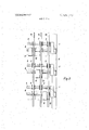
- FIG. 3 is a front view taken in the direction of arrow A of FIG. 2;
- FIGS. la, 2a and 3a are views similar to FIGS. 1, 2, 3, respectively, of an alternative embodiment of the present invention.
- FIGS. 1-3 which illustrate the invention applied to a circular knitting machine:
- a rail in the form of a ring 2 is secured to the frame of the machine.
- Carrier arms 1 are clamped to the rail 2 by means of a depending claw and a holding or tightening screw 4 (FIG. I).
- the carrier arm 1 best seen in the top view of FIG. 2, is angled.
- a vertically upstanding rod 5 is located at the tip of the angle, and a second and preferably similar rod 6 is located intermediate the length of the arm 1, for example near the apex of the angle.
- Arm 1 may haveother shapes, forexample may be straight, bowed or the like.
- Idle-r compensating pulleys 7 are located, in height-adjustable position to be rotatable about rod 5, for example by ball bearings whose height position on the rod 5 can be determined by a small set screw (not shown).
- Three drive belts 8, 9, 10 run in a plane parallel to the plane of the ring 2, but staggered vertically (see FIGS. 1 and 3).
- the rod 6 serves to secure Sachs ll thereto by means of a projecting arm 13 clamped by clamp screws 16 to a radial clamp 14 which can, in turn, be clamped to the vertical rod 6.
- loosening and re-positioning clamp 14 vertically permits placement of ashamed 11, with its drive pulley 12, in engagement with any one of the belts 8, 9 and 10; as shown in FIG.
- the tents' seur 11 is engaged by belt 10.
- the secondtician (from the left) is engaged by belt 9 and the third tribe is engaged by belt 8.
- the radial position that is the projection of the respective convinceds l1, and their drive pulleys 12 with respect to the center of the machine (or, in other words, with respect to the path of the belts 8, 9, 10) is adjustable by adjusting the length of arm 13 upon re-positioning clamp 16.
- the representatives 11 thus can be located with respect to the belts in any desired vertical, as well as radially projecting position.
- FIGS. 1-3 provide for three different belt drives, located in three respective vertical planes. Each noted is provided with an electrical contact which is led over a flexible cable 17 to a thread control or thread break sensing device; for interconnection, a quick-release plug-socket connection with an electrical bus system 17' is provided, bus system 17 being located along rail 2.
- idler pulleys 20, 20 and 22 are located in vertically staggered position on an arm 1 (FIG. 2) which, in all respects, may be similar to arms 1 on which the concludeds and pulleys 7 are located.
- the idler pulleys 20, 20 are preferably located on a transverse arm which may be tensioned, in the form of a tension balance 21, as well known, the arm itself being carried on an extension bar 23 which can be clamped in height-adjustable and radial adjustable position by locating brackets 24, 25 on rods 5', 6 similar to rods 5, 6, on arms 1.
- arm 23 with its tension-balance pulleys 20, 20' and the terminal idler pulley 22 can be located in height-adjusted position, and the extent of projection of the arm 23, and with it the extent of the loop formed by the belt as it is looped from the main drive around the idler pulley 22 and back over the tension balance wheel 20' is likewise subject to radial adjustment.
- Similar pulley arrangements are located, vertically staggered, for all the belts, the extent of radial projection of the arm 23 being matched to the number of practicess driven by the respective belts.
- the adjustmentof the length of the belt in dependence on whether the belt drives a treat or not is rather small, since the radial position of the idler pulleys 7 and the adopted pulley 10 can be adjusted to be fairly similar, requiring only small adjustments of the bracket 23, to the extent that they cannot be compensated by the tension balance 21.
- FIGS. 1a, 2a, 3a illustrates a form of the invention in which only a single support rod 6 is secured to shorter arms la which are, again, clamped to a ring 2.
- Fournisseurs 11 are located on rod 6, to be height-adjustable and radially adjustable, as in the embodiment described in connection with FIGS. 1-3.
- the idler pulleys 7, however, are omitted. This may result in a belt position pattern which causes some belts to pass on the inside, that is beneath other sentencess 11, as illustrated in connection with belt 8 (FIGS. 1a, 2a).
- the length-adjustment for the belts may thus be more extensive.
- An arm la which is straight, is clamped to rail 2.
- brackets 34, 35 are clamped by screw clamps (not shown).
- the brackets 34, 35 in turn carry a horizontally projecting rod 33 to which idler pulleys 30, 30' and 32 are rotatably connected, idler pulleys 30, 30' being located on a tension balance 31.
- the placement of the tension balance 31 and of the idler pulley 32 longitudinally on rod 33 may be, for example, by a short stub shaft clamped in position on the rod 33 by a quick-release clamp, not shown for simplicity and well known in the art.
- the arm 13 carrying thewholesome 11 is preferably hollow so that the cable 17 can be carried through the arm 13, and then connected, so that it will be protected from possible contact with the freely running belts which may be adjacent the rods 6.
- Thread supply apparatus for textile machines comprising a plurality of thread supply units (11, 12);
- dirven belts (8, 9, 10) located in staggered, offset planes, and essentially parallel to each other;
- clamping means 13, 14; 15, 16 interconnecting the thread supply unit (l1, l2) and the projecting rod (6), said clamping means being adjustable on the rod in a direction of the stagger of the belts for engagement of a selected thread supply unit with a selected belt and said thread supply unit being further adjustable in projecting position with respect to the clamping means and the rail (2) of the machine to provide for lengthcompensation of the belt, and engagement position of a selected thread supply unit with the respective belt.
- Apparatus according to claim 1 in combination with a circular knitting machine, wherein the common support rail is a ring (2) enclosing the machine;
- each of the support arms to the rail comprises a quick-release clamping means (3, 4) clamping the support arm to the ring, the projecting position of the thread supply units being adjustable radially with respect to the machine.
- Apparatus according to claim 2, wherein the 'quick-release clamping means comprises a claw (3) formed on each arm adapted to hook over the ring (2); and a clamp screw bearing against the ring to clamp the claw to the ring.
- Apparatus according to claim 2 comprising a further support arm (1) carrying radially adjustably mounted idler pulleys (20, 20, 22; 30, 30', 32) having said driven belts (8, 9, 10) passing thereover to provide for length-compensation of the driven belts, said further support arm (1'), and said support arms for the thread supply units being similar.
- each support arm extends substantially horizontally and two rods (5, 6) are provided projecting in a vertical direction from each support arm (1), one of said rods (5) being located adjacent the free end of the support arm, and idler pulleys (7) rotatably mounted in longitudinal staggered relation on said one support rod;
- the other rod (6) being located intermediate the length of the support arm and carrying said thread supply unit (11, 12).
- Apparatus according to claim 5 wherein the belts (8, 9, 10) run in essentially staggered horizontal planes and surround the idler pulleys (7) at selected feeds of 7.
Landscapes
- Engineering & Computer Science (AREA)
- Textile Engineering (AREA)
- Knitting Machines (AREA)
Abstract
To permit ready selective use of thread supply apparatus in textile machines, particularly circular knitting machines, a plurality of support arms, all similar, are clamped to a rail on the machine (which may be a ring for a circular knitting machine). The arms carry projecting rods which extend at right angles to the planes in which drive belts are continuously driven from the machine, to permit selective vertical adjustment of thread supply apparatus to be engaged by selected ones of the drive belts. In one form of the invention, the arms carry two vertical rods, one for idler pulleys around which the drive belts can be looped and the other for the thread supply apparatus itself, so that dismounting and re-mounting of the thread supply apparatus can be eliminated by mere selective engagement of the belts with the thread supply apparatus, or the idler pulleys, respectively, the thread supply apparatus itself being mounted for both vertical as well as radial adjustment on their mounting rods.
Description
United States Patent 19] Hebbecker et al.
[451 Jan. 15,1974
1 1 THREAD SUPPLY APPARATUS FOR TEXTILE MACHINERY, PARTICULARLY CIRCULAR KNITTING MACHINES [75] Inventors: Roll Hebbecker, Bodelshausen;
Robert Hofmann, Rottenburg, both of Germany [73] Assignee: Fouguet-Werk Frauz & Planck,
Rottenburg am Neckar, Germany [22] Filed: June 13, 1972 [21] Appl. N0.: 262,409
[30] Foreign Application Priority Data June 21, 1971 Germany P 21 30 697.8
[52] U.S. Cl. .1 66/132 T, 242/4701 [51] Int. Cl D041) 15/48 [58] Field of Search 66/125 R, 132 R, 1 66/132 T; 242/4701, 47.12
[56] References Cited UNITED STATES PATENTS 2,967,413 l/196l Jackson et al. 66/132 R 3,243,091 3/1966 Rosen 66/132 T X 3,418,831 12/1968 Nance 66/132 T 3,490,710 1/1970 Muhlhausler 242/4701 3,625,444 12/1971 Hatay 242/4701 Tannert 242/47.12 X Muhlhausler 242/4701 X [57] ABSTRACT To permit ready selective use of thread supply apparatus in textile machines, particularly circular knitting machines, a plurality of support arms, all similar, are clamped to a rail on the machine (which may be a ring for a circular knitting machine). The arms carry projecting rods which extend at right angles to the planes in which drive belts are continuously driven from the machine, to permit selective vertical adjustment of thread supply apparatus to be engaged by selected ones of the drive belts. In one form of the invention, the arms carry two vertical rods, one for idler pulleys around which the drive belts can be looped and the other for the thread supply apparatus itself, so that dismounting and re-mounting of the thread supply apparatus can be eliminated by mere selective engagement of the belts with the thread supply apparatus, or the idler pulleys, respectively, the thread supply apparatus itself being mounted for both vertical as well as radial adjustment on their mounting rods.
7 Claims, 6 Drawing Figures IMENTED JAN 15 im SHEEI 3 OF THREAD SUPPLY APPARATUS FOR TEXTILE MACHINERY, PARTICULARLY CIRCULAR KNITTING MACHINES The present invention relates to thread supply apparatus and more particularly to thread storing devices, also known as furnishing wheels, or drums, or fournisseurs for circular knitting machines.
Various types of thread supply apparatus have been proposed see, for example US. Pat. No. 3,490,710.
These thread supply devices are located on the knitting machine between the yarn package and the knitting feeds, that is, where the yarn is applied to the knit ting needles. In one form, the fournisseurs are located in various horizontal planes on concentric rings secured to the machine structure, and various drive belts of differential drive speed run in the various planes, drive belts of respective speeds being applied to fournisseurs in dependence on the desired quantity of thread to be supplied. In one form which is customary, the belts running around the machine are endless belts which are partially looped about the respective selected fournisseurs, the belts being driven from a common drive and each belt providing a drive to the re spective fournisseurs at a common drive speed, so that each fournisseur is driven with the same speed from the same source.
If the pattern to be knitted, or the stitch structure of the fabric is changed, different supply speeds may be required. To permit different supply speeds, belts are located in various planes and it has, in the past, been necessary to dismount the fournisseurs from one plane and from the engagement with a given belt and re mount and secure the fournisseurs in a different plane, with a new attachment, if change of drive speed from one belt to another was desired. This dismounting and re-mounting of the fournisseurs or their carriers is time consuming and requires, after re-mounting, accurate positioning of the fournisseurs with respect to the drive belt. After re-mounting of selected fournisseurs, the respective drive belt may have more fournisseurs in driving engagement therewith than previously, which changes the circumferential aspects of the belt, and changes its length along the circumference of the machine, unless the length of the belt itself as it runs around the machine can be readily adjusted, that is, compensated for the presence of additional fournisseurs. If, on the other hand, some fournisseurs are removed, the belt again requires re-adjustment in its length.
It is an object of the present invention to provide a textile machine thread supply structure, and more par ticularly a structure for circular knitting machines which permits easy change of position of fournisseurs with respect to a group of drive belts, located in various staggered planes, and to permit easy adjustment of the length of the belt, while having minimum interference with the remaining fournisseurs and their previous location.
SUBJECT MATTER OF THE PRESENT INVENTION Briefly, common carrier arms are provided which are mounted on a machine rail in the case of circular knitting machines on a support ring preferably by means of a quick-release clamp. The arms are formed with a projecting rod on which the fournisseurs are mounted, individually adjustable for height as well as for projection from the plane in which the belts travel, so that their radial projection (in case of circular knitting machines) can be easily adjusted for effective driving engagement with the belt. The belt, itself, in accordance with a feature of the invention, is adjusted for length by running the belt around a group of idler pulleys mounted on an arm similar to the arms carrying the rods on which the fournisseurs are located, so that a minimum of different structures, and thus parts are necessary.
In accordance with a feature of the invention, the arms are provided with two projecting rods, radially staggered from each other, the outer rod carrying idler pulleys and the inner rod carrying "the support arms for the fournisseur, so that, if a fournisseur is to be disengaged, the belt can be looped about the idler pulley to be kept out of the way and requiring a minimum of readjustment of belt length.
The invention will be described by way of example with reference to the accompanying drawings, wherein:
FIG. I is a highly schematic side view of a carrier arm, with projecting rods and a fournisseur mounted thereon;
FIG. 2 is a top view of a drive arrangement for fournisseurs for a circular machine; 5
FIG. 3 is a front view taken in the direction of arrow A of FIG. 2; and
FIGS. la, 2a and 3a are views similar to FIGS. 1, 2, 3, respectively, of an alternative embodiment of the present invention.
Referring first to FIGS. 1-3, which illustrate the invention applied to a circular knitting machine: A rail in the form of a ring 2 is secured to the frame of the machine. Carrier arms 1 are clamped to the rail 2 by means of a depending claw and a holding or tightening screw 4 (FIG. I). The carrier arm 1, best seen in the top view of FIG. 2, is angled. A vertically upstanding rod 5 is located at the tip of the angle, and a second and preferably similar rod 6 is located intermediate the length of the arm 1, for example near the apex of the angle. Arm 1 may haveother shapes, forexample may be straight, bowed or the like. Idle-r compensating pulleys 7 are located, in height-adjustable position to be rotatable about rod 5, for example by ball bearings whose height position on the rod 5 can be determined by a small set screw (not shown). Three drive belts 8, 9, 10 run in a plane parallel to the plane of the ring 2, but staggered vertically (see FIGS. 1 and 3). The rod 6 serves to secure fournisseurs ll thereto by means of a projecting arm 13 clamped by clamp screws 16 to a radial clamp 14 which can, in turn, be clamped to the vertical rod 6. Thus, loosening and re-positioning clamp 14 vertically permits placement of fournisseur 11, with its drive pulley 12, in engagement with any one of the belts 8, 9 and 10; as shown in FIG. 1, the fournis' seur 11 is engaged by belt 10. As seen in FIG. 3, the second fournisseur (from the left) is engaged by belt 9 and the third fournisseur is engaged by belt 8. The radial position, that is the projection of the respective fournisseurs l1, and their drive pulleys 12 with respect to the center of the machine (or, in other words, with respect to the path of the belts 8, 9, 10) is adjustable by adjusting the length of arm 13 upon re-positioning clamp 16. The fournisseurs 11 thus can be located with respect to the belts in any desired vertical, as well as radially projecting position.
The examples illustrated in FIGS. 1-3 provide for three different belt drives, located in three respective vertical planes. Each fournisseur is provided with an electrical contact which is led over a flexible cable 17 to a thread control or thread break sensing device; for interconnection, a quick-release plug-socket connection with an electrical bus system 17' is provided, bus system 17 being located along rail 2.
The belt itself is driven from a central drive, not shown; to adjust for the length of the belt coursing about the fournisseurs, idler pulleys 20, 20 and 22 are located in vertically staggered position on an arm 1 (FIG. 2) which, in all respects, may be similar to arms 1 on which the fournisseurs and pulleys 7 are located. The idler pulleys 20, 20 are preferably located on a transverse arm which may be tensioned, in the form of a tension balance 21, as well known, the arm itself being carried on an extension bar 23 which can be clamped in height-adjustable and radial adjustable position by locating brackets 24, 25 on rods 5', 6 similar to rods 5, 6, on arms 1. The clamp connections between the brackets 24, 25 have been omitted from the drawings for clarity and may be similar to clamps l5 and 16. Thus, arm 23 with its tension-balance pulleys 20, 20' and the terminal idler pulley 22 can be located in height-adjusted position, and the extent of projection of the arm 23, and with it the extent of the loop formed by the belt as it is looped from the main drive around the idler pulley 22 and back over the tension balance wheel 20' is likewise subject to radial adjustment.
Similar pulley arrangements are located, vertically staggered, for all the belts, the extent of radial projection of the arm 23 being matched to the number of fournisseurs driven by the respective belts. As can be seen from FIG. 2, the adjustmentof the length of the belt in dependence on whether the belt drives a fournisseur or not is rather small, since the radial position of the idler pulleys 7 and the fournisseur pulley 10 can be adjusted to be fairly similar, requiring only small adjustments of the bracket 23, to the extent that they cannot be compensated by the tension balance 21.
The embodiment shown in FIGS. 1a, 2a, 3a, likewise applied to a circular knitting machine, illustrates a form of the invention in which only a single support rod 6 is secured to shorter arms la which are, again, clamped to a ring 2. Fournisseurs 11 are located on rod 6, to be height-adjustable and radially adjustable, as in the embodiment described in connection with FIGS. 1-3. The idler pulleys 7, however, are omitted. This may result in a belt position pattern which causes some belts to pass on the inside, that is beneath other fournisseurs 11, as illustrated in connection with belt 8 (FIGS. 1a, 2a). The length-adjustment for the belts may thus be more extensive. An arm la, which is straight, is clamped to rail 2. It carries a pair of upstanding rods 38, 39, to which brackets 34, 35 are clamped by screw clamps (not shown). The brackets 34, 35 in turn carry a horizontally projecting rod 33 to which idler pulleys 30, 30' and 32 are rotatably connected, idler pulleys 30, 30' being located on a tension balance 31. The placement of the tension balance 31 and of the idler pulley 32 longitudinally on rod 33 may be, for example, by a short stub shaft clamped in position on the rod 33 by a quick-release clamp, not shown for simplicity and well known in the art.
In the form of the invention illustrated in FIGS. 1a-3a, the arm 13 carrying the fournisseur 11 is preferably hollow so that the cable 17 can be carried through the arm 13, and then connected, so that it will be protected from possible contact with the freely running belts which may be adjacent the rods 6.
Various changes and modifications may be made within the inventive concept.
We claim:
1. Thread supply apparatus for textile machines comprising a plurality of thread supply units (11, 12);
a group of dirven belts (8, 9, 10) located in staggered, offset planes, and essentially parallel to each other;
a support arm (1, 1a) located to support each thread supply unit;
a common support rail (2) secured to the frame of the machine;
means (3, 4) securing said support arms (1, 1a) to the common support rail (2);
a projecting rod (6) extending from each of the support arms;
and adjustable clamping means (13, 14; 15, 16) interconnecting the thread supply unit (l1, l2) and the projecting rod (6), said clamping means being adjustable on the rod in a direction of the stagger of the belts for engagement of a selected thread supply unit with a selected belt and said thread supply unit being further adjustable in projecting position with respect to the clamping means and the rail (2) of the machine to provide for lengthcompensation of the belt, and engagement position of a selected thread supply unit with the respective belt.
2. Apparatus according to claim 1, in combination with a circular knitting machine, wherein the common support rail is a ring (2) enclosing the machine;
and the means securing each of the support arms to the rail comprises a quick-release clamping means (3, 4) clamping the support arm to the ring, the projecting position of the thread supply units being adjustable radially with respect to the machine.
3. Apparatus according to claim 2, wherein the 'quick-release clamping means comprises a claw (3) formed on each arm adapted to hook over the ring (2); and a clamp screw bearing against the ring to clamp the claw to the ring.
4. Apparatus according to claim 2, comprising a further support arm (1) carrying radially adjustably mounted idler pulleys (20, 20, 22; 30, 30', 32) having said driven belts (8, 9, 10) passing thereover to provide for length-compensation of the driven belts, said further support arm (1'), and said support arms for the thread supply units being similar.
5. Apparatus according to claim 1, in combination with a circular knitting machine wherein each support arm extends substantially horizontally and two rods (5, 6) are provided projecting in a vertical direction from each support arm (1), one of said rods (5) being located adjacent the free end of the support arm, and idler pulleys (7) rotatably mounted in longitudinal staggered relation on said one support rod;
the other rod (6) being located intermediate the length of the support arm and carrying said thread supply unit (11, 12).
6. Apparatus according to claim 5, wherein the belts (8, 9, 10) run in essentially staggered horizontal planes and surround the idler pulleys (7) at selected feeds of 7. Apparatus according to claim 5, wherein the idler pulleys (7) are mounted on said one rod (5) for vertical adjustment and said thread supply units (l1, 12) are mounted on the other rod (6) for both vertical as well as horizontal adjustment;
and said belts (8, 9, 10) run in staggered, essentially horizontal planes.
Claims (7)
1. Thread supply apparatus for textile machines comprising a plurality of thread supply units (11, 12); a group of driven belts (8, 9, 10) located in staggered, offset planes, and essentially parallel to each other; a support arm (1, 1a) located to support each thread supply unit; a common support rail (2) secured to the frame of the machine; means (3, 4) securing said support arms (1, 1a) to the common support rail (2); a projecting rod (6) extending from each of the support arms; and adjustable clamping means (13, 14; 15, 16) interconnecting the thread supply unit (11, 12) and the projecting rod (6), said clamping means being adjustable on the rod in a direction of the stagger of the belts for engagement of a selected thread supply unit with a selected belt and said thread supply unit being further adjustable in projecting position with respect to the clamping means and the rail (2) of the machine to provide for length-compensation of the belt, and engagement position of a selected thread supply unit with the respective belt.
2. Apparatus according to claim 1, in combination with a circular knitting machine, wherein the common support rail is a ring (2) enclosing the machine; and the means securing each of the support arms to the rail comprises a quick-release clamping means (3, 4) clamping the support arm to the ring, the projecting position of the thread supply units being adjustable radially with respect to the machine.
3. Apparatus according to claim 2, wherein the quick-release clamping means comprises a claw (3) formed on each arm adapted to hook over the ring (2); and a clamp screw bearing against the ring to clamp the claw to the ring.
4. Apparatus according to claim 2, comprising a further support arm (1'') carrying radially adjustably mounted idler pulleys (20, 20'', 22; 30, 30'', 32) having said driven belts (8, 9, 10) passing thereover to provide for length-compensation of the driven belts, said further support arm (1''), and said support arms for the thread supply units being similar.
5. Apparatus according to claim 1, in combination with a circular knitting machine wherein each support arm extends substantially horizontally and two rods (5, 6) are provided projecting in a vertical direction from each support arm (1), one of said rods (5) being located adjacent the free end of the support arm, and idler pulleys (7) rotatably mounted in longitudinal staggered relation on said one support rod; the other rod (6) being located intermediate the length of the support arm and carrying said thread supply unit (11, 12).
6. Apparatus according to claim 5, wherein the belts (8, 9, 10) run in essentially staggered horizontal planes and surround the idler pulleys (7) at selected feeds of the machine and engage the thread supply units at other selected feeds; said thread supply units being located in vertically adjustable position to be engaged by the belts at feeds where thread is desired to be supplied and being located out of contact with the respective belt where no thread is desired to be delivered, the belts at said no-thread delivery feeds being looped about the respective idler pulleys (7).
7. Apparatus according to claim 5, wherein the idler pulleys (7) are mounted on said one rod (5) for vertical adjustment and said thread supply units (11, 12) are mounted on the other rod (6) for both vertical as well as horizontal adjustment; and said belts (8, 9, 10) run in staggered, essentially horizontal planes.
Applications Claiming Priority (1)
| Application Number | Priority Date | Filing Date | Title |
|---|---|---|---|
| DE19712130697 DE2130697A1 (en) | 1971-06-21 | 1971-06-21 | MOUNTING DEVICE FOR THREAD SUPPLY DEVICES OF CIRCULAR KNITTING AND CIRCULAR MILLING MACHINES |
Publications (1)
| Publication Number | Publication Date |
|---|---|
| US3785176A true US3785176A (en) | 1974-01-15 |
Family
ID=5811344
Family Applications (1)
| Application Number | Title | Priority Date | Filing Date |
|---|---|---|---|
| US00262409A Expired - Lifetime US3785176A (en) | 1971-06-21 | 1972-06-13 | Thread supply apparatus for textile machinery, particularly circular knitting machines |
Country Status (11)
| Country | Link |
|---|---|
| US (1) | US3785176A (en) |
| BE (1) | BE785158A (en) |
| BR (1) | BR7204001D0 (en) |
| CH (1) | CH551516A (en) |
| DE (1) | DE2130697A1 (en) |
| ES (1) | ES404054A1 (en) |
| FR (1) | FR2143153B1 (en) |
| GB (1) | GB1371576A (en) |
| IT (1) | IT959084B (en) |
| NL (1) | NL7208243A (en) |
| SE (1) | SE367220B (en) |
Cited By (7)
| Publication number | Priority date | Publication date | Assignee | Title |
|---|---|---|---|---|
| US3901479A (en) * | 1971-12-13 | 1975-08-26 | Western Gear Corp | Traction type hoist |
| US4047398A (en) * | 1974-12-31 | 1977-09-13 | Firma Gustav Memminger Verfahrenstechnik Fur Die Maschenindustrie | Yarn guide finger for positive yarn supply apparatus |
| US4136837A (en) * | 1976-08-31 | 1979-01-30 | Gustav Memminger Verfahrenstechnik Fur Die Maschenindustrie | Positive tape feed with multiple yarn windings |
| US4165048A (en) * | 1976-08-12 | 1979-08-21 | Horst Paepke | Positive feed |
| US4318285A (en) * | 1978-06-28 | 1982-03-09 | Aktiebolaget Iro | Apparatus for the positive delivery of thread to circular knitting machines |
| US4759201A (en) * | 1982-04-29 | 1988-07-26 | Alfred Beck | Winding thread device |
| US20150097065A1 (en) * | 2013-10-03 | 2015-04-09 | C-Tech Oil Well Technologies Inc. | Coiled rod reel |
Families Citing this family (1)
| Publication number | Priority date | Publication date | Assignee | Title |
|---|---|---|---|---|
| DE2365251C2 (en) * | 1973-04-30 | 1983-02-17 | Aktiebolaget Iro, Ulricehamn | Yarn feeding device for textile machines |
Citations (7)
| Publication number | Priority date | Publication date | Assignee | Title |
|---|---|---|---|---|
| US2967413A (en) * | 1957-12-23 | 1961-01-10 | Mellar Bromley & Co Ltd | Yarn feeding and controlling means for knitting machines |
| US3243091A (en) * | 1962-03-08 | 1966-03-29 | Rosen Karl Isac Joel | Yarn feeding equipment |
| US3418831A (en) * | 1967-10-27 | 1968-12-31 | Ertle Williamson | Feed control for automatic striper |
| US3490710A (en) * | 1967-07-31 | 1970-01-20 | Fouquet Werk Frauz & Planck | Automatic thread delivery device for textile machines |
| US3625444A (en) * | 1970-01-28 | 1971-12-07 | Fouquet Werk Frauz & Plank Fa | Thread supply apparatus for textile machinery |
| US3709444A (en) * | 1969-08-19 | 1973-01-09 | K Tannert | Positive thread feeder for circular knitting machines with a plurality of knitting points |
| US3713307A (en) * | 1971-12-23 | 1973-01-30 | Fouquet Werk Frauz & Planck | Thread supply device for textile machinery |
-
1971
- 1971-06-21 DE DE19712130697 patent/DE2130697A1/en active Pending
-
1972
- 1972-05-26 SE SE06895/72A patent/SE367220B/xx unknown
- 1972-06-08 IT IT68823/72A patent/IT959084B/en active
- 1972-06-13 US US00262409A patent/US3785176A/en not_active Expired - Lifetime
- 1972-06-16 NL NL7208243A patent/NL7208243A/xx unknown
- 1972-06-20 BE BE785158A patent/BE785158A/en unknown
- 1972-06-20 CH CH926172A patent/CH551516A/en not_active IP Right Cessation
- 1972-06-20 FR FR727222257A patent/FR2143153B1/fr not_active Expired
- 1972-06-20 ES ES404054A patent/ES404054A1/en not_active Expired
- 1972-06-20 BR BR4001/72A patent/BR7204001D0/en unknown
- 1972-06-21 GB GB2896572A patent/GB1371576A/en not_active Expired
Patent Citations (7)
| Publication number | Priority date | Publication date | Assignee | Title |
|---|---|---|---|---|
| US2967413A (en) * | 1957-12-23 | 1961-01-10 | Mellar Bromley & Co Ltd | Yarn feeding and controlling means for knitting machines |
| US3243091A (en) * | 1962-03-08 | 1966-03-29 | Rosen Karl Isac Joel | Yarn feeding equipment |
| US3490710A (en) * | 1967-07-31 | 1970-01-20 | Fouquet Werk Frauz & Planck | Automatic thread delivery device for textile machines |
| US3418831A (en) * | 1967-10-27 | 1968-12-31 | Ertle Williamson | Feed control for automatic striper |
| US3709444A (en) * | 1969-08-19 | 1973-01-09 | K Tannert | Positive thread feeder for circular knitting machines with a plurality of knitting points |
| US3625444A (en) * | 1970-01-28 | 1971-12-07 | Fouquet Werk Frauz & Plank Fa | Thread supply apparatus for textile machinery |
| US3713307A (en) * | 1971-12-23 | 1973-01-30 | Fouquet Werk Frauz & Planck | Thread supply device for textile machinery |
Cited By (8)
| Publication number | Priority date | Publication date | Assignee | Title |
|---|---|---|---|---|
| US3901479A (en) * | 1971-12-13 | 1975-08-26 | Western Gear Corp | Traction type hoist |
| US4047398A (en) * | 1974-12-31 | 1977-09-13 | Firma Gustav Memminger Verfahrenstechnik Fur Die Maschenindustrie | Yarn guide finger for positive yarn supply apparatus |
| US4165048A (en) * | 1976-08-12 | 1979-08-21 | Horst Paepke | Positive feed |
| US4136837A (en) * | 1976-08-31 | 1979-01-30 | Gustav Memminger Verfahrenstechnik Fur Die Maschenindustrie | Positive tape feed with multiple yarn windings |
| US4318285A (en) * | 1978-06-28 | 1982-03-09 | Aktiebolaget Iro | Apparatus for the positive delivery of thread to circular knitting machines |
| US4759201A (en) * | 1982-04-29 | 1988-07-26 | Alfred Beck | Winding thread device |
| US4759200A (en) * | 1982-04-29 | 1988-07-26 | Alfred Beck | Winding thread device |
| US20150097065A1 (en) * | 2013-10-03 | 2015-04-09 | C-Tech Oil Well Technologies Inc. | Coiled rod reel |
Also Published As
| Publication number | Publication date |
|---|---|
| NL7208243A (en) | 1972-12-27 |
| DE2130697A1 (en) | 1973-01-11 |
| GB1371576A (en) | 1974-10-23 |
| FR2143153B1 (en) | 1973-07-13 |
| ES404054A1 (en) | 1975-06-01 |
| CH551516A (en) | 1974-07-15 |
| BR7204001D0 (en) | 1973-06-07 |
| FR2143153A1 (en) | 1973-02-02 |
| DE2130697B2 (en) | 1974-09-19 |
| BE785158A (en) | 1972-10-16 |
| IT959084B (en) | 1973-11-10 |
| SE367220B (en) | 1974-05-20 |
Similar Documents
| Publication | Publication Date | Title |
|---|---|---|
| US3785176A (en) | Thread supply apparatus for textile machinery, particularly circular knitting machines | |
| US3090215A (en) | Device for guided feeding of yarn to knitting machines | |
| US3709444A (en) | Positive thread feeder for circular knitting machines with a plurality of knitting points | |
| JPH05505858A (en) | Method of knitting non-woven fabric etc. and non-woven fabric knitting device | |
| US4671083A (en) | Driving apparatus in take up unit of circular knitting machine | |
| US6283397B1 (en) | Variable and steady yarn feeding apparatus | |
| US3922887A (en) | Positive yarn feeding system for circular knitting machine | |
| US4138866A (en) | Yarn delivery apparatus, especially for knitting machines | |
| US3949573A (en) | Thread delivery device for textile machines | |
| US3847099A (en) | Ribbon feeding attachment for sewing machines | |
| US2746410A (en) | Uniform tension feeding mechanism | |
| US3590601A (en) | Apparatus for feeding elastic yarn to a circular knitting machine | |
| GB2065723A (en) | Self actuating yarn feed and drive belt arrangement for circular knitting machines | |
| US4147311A (en) | Tape/capstan feed unit | |
| US3962890A (en) | Straight knitting machine comprising rotating sliding heads | |
| US3618342A (en) | Device for the feed of elastomer threads particularly in circular knitting machines | |
| US3478945A (en) | Yarn supplying means for knitting machines | |
| US3858830A (en) | Positive yarn feeding device | |
| ES8407536A1 (en) | Yarn feeder for circular knitting machine equipped with stripers. | |
| US2387100A (en) | Electric distributor ring for rotary knitting machines | |
| US3651668A (en) | Yarn feeding means for knitting machines | |
| US3762185A (en) | Bobbin crafting and thread feeding device for circular knitting machines | |
| JPH0224942B2 (en) | ||
| US3045459A (en) | Fiber control for pile fabric knitting machines | |
| ES482029A1 (en) | Apparatus for the positive delivery of thread to circular knitting machines |