US3774561A - Article of manufacture and manufacturing of such article - Google Patents
Article of manufacture and manufacturing of such article Download PDFInfo
- Publication number
- US3774561A US3774561A US00200128A US3774561DA US3774561A US 3774561 A US3774561 A US 3774561A US 00200128 A US00200128 A US 00200128A US 3774561D A US3774561D A US 3774561DA US 3774561 A US3774561 A US 3774561A
- Authority
- US
- United States
- Prior art keywords
- deep
- basins
- sheet
- drawn
- depth
- Prior art date
- Legal status (The legal status is an assumption and is not a legal conclusion. Google has not performed a legal analysis and makes no representation as to the accuracy of the status listed.)
- Expired - Lifetime
Links
- 238000004519 manufacturing process Methods 0.000 title claims description 10
- 238000000034 method Methods 0.000 claims abstract description 19
- 229910001220 stainless steel Inorganic materials 0.000 claims abstract description 15
- 239000010935 stainless steel Substances 0.000 claims abstract description 15
- 238000007493 shaping process Methods 0.000 claims description 2
- 239000000463 material Substances 0.000 description 13
- 238000010276 construction Methods 0.000 description 4
- 238000003466 welding Methods 0.000 description 4
- 230000015572 biosynthetic process Effects 0.000 description 2
- 229910000831 Steel Inorganic materials 0.000 description 1
- 230000006978 adaptation Effects 0.000 description 1
- 239000011111 cardboard Substances 0.000 description 1
- 239000011159 matrix material Substances 0.000 description 1
- 238000012986 modification Methods 0.000 description 1
- 230000004048 modification Effects 0.000 description 1
- 239000011087 paperboard Substances 0.000 description 1
- 238000005498 polishing Methods 0.000 description 1
- 238000004826 seaming Methods 0.000 description 1
- 239000010959 steel Substances 0.000 description 1
Images


Classifications
-
- B—PERFORMING OPERATIONS; TRANSPORTING
- B21—MECHANICAL METAL-WORKING WITHOUT ESSENTIALLY REMOVING MATERIAL; PUNCHING METAL
- B21D—WORKING OR PROCESSING OF SHEET METAL OR METAL TUBES, RODS OR PROFILES WITHOUT ESSENTIALLY REMOVING MATERIAL; PUNCHING METAL
- B21D22/00—Shaping without cutting, by stamping, spinning, or deep-drawing
- B21D22/20—Deep-drawing
- B21D22/26—Deep-drawing for making peculiarly, e.g. irregularly, shaped articles
-
- B—PERFORMING OPERATIONS; TRANSPORTING
- B21—MECHANICAL METAL-WORKING WITHOUT ESSENTIALLY REMOVING MATERIAL; PUNCHING METAL
- B21D—WORKING OR PROCESSING OF SHEET METAL OR METAL TUBES, RODS OR PROFILES WITHOUT ESSENTIALLY REMOVING MATERIAL; PUNCHING METAL
- B21D51/00—Making hollow objects
- B21D51/16—Making hollow objects characterised by the use of the objects
- B21D51/18—Making hollow objects characterised by the use of the objects vessels, e.g. tubs, vats, tanks, sinks, or the like
-
- E—FIXED CONSTRUCTIONS
- E03—WATER SUPPLY; SEWERAGE
- E03C—DOMESTIC PLUMBING INSTALLATIONS FOR FRESH WATER OR WASTE WATER; SINKS
- E03C1/00—Domestic plumbing installations for fresh water or waste water; Sinks
- E03C1/12—Plumbing installations for waste water; Basins or fountains connected thereto; Sinks
- E03C1/18—Sinks, whether or not connected to the waste-pipe
Definitions
- a sink unit is deep-drawn from a one-piece seamless Nov. 21, 1970 Germany P 20 57 339.! stainless steel sheet, being provided with two basins which are laterally adjacent one another and with a [52] U.S. C1. 113/120 B, 72/349 work urface which is laterally adjacent one of th b [51] Int. Cl. B2ld 51/18 sins.
- a method of deep-drawing such a sink unit, and [58] Field of Search 113/ 120 B, 120 R; an arrangement for engaging it during deep-drawing 72/348, 349, 350, 351 are also disclosed.
- the present invention relates generally to a sink unit and more particularly to a multiple-basin sink unit and a method of making the same.
- Sink units are already known. They are so constructed that they can usually be inserted into a cut-out of a counter top or the like, and are quite frequently made of rust-free stainless steel sheet. Many such sink units have two basins which are located laterally adjacent one another, being separated by a narrow strip of sheet material. Such sink units are produced in that each separate basin is separately produced by deepdrawing from a sheet of stainless steel, and then the two separate basins are welded together so that a welded seam extends intermediate them in the narrow sheet material strip which is located between them and which separates them.
- Another known sink unit utilizes a single basin, laterally of which there is located a work and- /or drain surface. This construction does not require a welded seam because only a single basin is produced by deep-drawing from a single sheet of stainless steel.
- this singlebasin type of sink unit is the only type that can be produced by deep-drawing without requiring the subsequent provision of a welded seam to connect two components of the unit together.
- a concomitant object of the invention is to provide such a sink unit which can be produced by deepdrawing from a single piece of stainless steel sheet material without requiring any welding operations or the like.
- one feature of the invention resides accordingly in a sink unit as a novel article of manufacture, such sink unit being of a seamless one-piece sheet of stainless steel which defines a pair of closely laterally adjacent basins and a work surface laterally adjacent one of these basins.
- the invention thus has the advantage that the heretofore necessary welding operation and the subsequent grinding and polishing of the welded seam can be omitted, thereby saving time and labor and having less scrap produced because only a single sheet material element need be trimmed at its edges after the deep-drawing process is completed.
- the edge of the sink unit is flattened, then the heretofore necessary welded seams at the junctures of the downwardly bent edge flanges can also be omitted, so that the sink unit according to the present invention can be constructed in its entirety without ever having to resort to any welding operations whatsoever.
- the invention is all the more interesting because expert opinion has always held that a sink unit according to the present invention could not be produced by a deep-drawing for various reasons, including the assumption that at the narrow strip of sheet material between the laterally adjacent basis the sheet material was thought not to be capable of withstanding the stresses resulting during deep-drawing deformation.
- the invention is all the more surprising because it is feasible despite these expert reservations, and even more so because the deep-drawing process is of course made more difficult by the fact that laterally adjacent one of the basins there is the relatively large work and- /or drain surface whose provision was thought in expert opinion to add further obstacles to the production of a one-piece sink unit of the type herein disclosed.
- Known sink units which are seamless and of one piece but have only a single basin are deep-drawn in two or three deep-drawing steps.
- the essential sheet material deformation is effected during the first deepdrawing step, and if for instance the basin is to have a finished depth of 160 mm, then in a two-step deepdrawing operation the basin is deep-drawn to approximately 150 mm in the first step, and if the deepdrawing operation is of the three-step type, the basin is deep-drawn to approximately 145 mm in the first step. In the second step it is then drawn to approximately 150 mm, and in the third and final step tothe finished depth of 160 mm. This means that in either the twostep or three-step operation, the finished depth of the basin is almost reached during the first deep-drawing step.
- the present invention proposes, contrary to the teaching of the prior art, to utilize deep-drawing operations of the three-step type or of a typehaving more than three steps. It has been found particularly advantageous to anneal the sheet of stainless steel between the second and third deep-drawing step, an important feature in the method according to the present inven-1 tion for making the novel article. I have also found it advantageous to deep-draw the sheet in one direction and to one side during the first deep-drawing step, and to reverse the thus-obtained deformation in the second step and to deep-draw it to the opposite side to a depth greater than that achieved in the first step. In this manner tearing of the sheet material can be avoided with great reliability.
- the invention also proposes, contrary to the teaching of the prior art, to produce only a relatively small por tion of the final desired depth of the basin during the first deep-drawing step. It is'particularly advantageous to deep-draw the basins in the first deep-drawing step to only approximately 20-25 percent of the final desired depth. In the second deep-drawing step the basins are then drawn to approximately -75 percent of their final desired depth. If, following the earlier-mentioned example, it is assumed that the final desired depth of the basins is to be approximately mm, then the basins are deep-drawn in the first deep-drawing step to approximately 35 mm depth, with a tolerance of :2-3 mm, and in the second step to approximately 1 15 mm with a tolerance of +5 mm.
- the tools for the deep-drawing operation may be variously configurated in accordance with principles well known to those skilled in the art.
- a possible and inexpensive solution has been found in utilizing the same tool or die for the first and second deep-drawing step, whereas a different die, giving the final desired form for the basins, is utilized for the third deep-drawing step.
- the present invention proposes a device which is to assure the miminum formation of folds during the deepdrawing and tp provide maximum assurance against tearing of the sheet.
- This device is to engage the sheet during the deep-drawing operation with different strength at different locations, and in particular the arrangement according to the present invention engages the sheet most firmly along lines extending in parallelism and with spacing along the front and rear edges of the two laterally adjacent basins, but not to the respective outermost edges thereof, and an additional region of firmest engagement is along one lateral side of that basin which is remote from the work surface.
- the sheet is engaged with lesser firmness in the region of those edges of the basin adjacent the work surface which face towards the latter.
- FIG. 1 is a somewhat diagrammatic top-plan view of a sink unit according to the present invention
- FIG. 2 is a section taken on line II-II of FIG. 1;
- FIG. 3 is a fragmentary detail view, on an enlarged scale, of the corner of the edge portion which is encircled in FIG. 2;
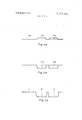
- FIGS. ,4a-4c are schematic views corresponding to the section of FIG. 2 but illustrating the sheet of stainless steel during the first, second, and third deepdrawing steps, respectively;
- FIG. 5 is a diagrammatic top-plan view illustrating a sheet of steel and an arrangement for engaging it in ac cordance with the invention during deep-drawing; and FIG. 6 is a schematic section of a drawing tool providing the arrangement according to FIG. 5, the section being taken according to line 6-6 of FIG. 5.
- reference numerals l0 and 12 define two basins provided in a sink unit according to the present invention, with a work and/or drain surface 14 being provided laterally adja cent the basin 10.
- the two basins l0 and 12 are separated by the illustrated narrow sheet material strip.
- the sink unit illustrated in FIGS. 1-3 is deep-drawn of a single seamless sheet of stainless steel and is provided along its rear edge with an upwardly extending portion 16, and at its side edges and front edge with downwardly angled L-shaped flanges 18 and 20.
- the juncture of the comers of the flanges l8 and 20 may be welded at 22, as shown in FIG. 1 and in accordance with the practice of the prior art, it is currently preferred to utilize the construction shown in FIG. 3 in which these flanges or edges are flattened in the region of these junctures, as indicated at 24 in FIG. 3, so that any need for producing welded seams is avoided, and the entire sink unit is produced without any welding at all.
- FIGS. 4a, 4b and 4c now show a possible and currently preferred deep-drawing method for making the sink unit according .to the present invention.
- the same deep-drawing tool or die used for producing the bulges 10a and 12a can be utilized for the second deepdrawing step illustrated in FIG.
- the sheet is annealed in accordance with well-known annealing-technique, and there follows the final deepdrawing step shown in FIG. 4c in whcih the bulges 10b and 12b are subjected to further deep-drawing until the final shape and depth of the basins 10 and 12 is reached.
- the surface 14 can also be provided with ribs or the like for drain purposes.
- FIG. 5 finally, shows a top-plan view of a sheet of stainless steel, on which the regions l0, l2 and 14 have been illustrated for purposes of orientation, showing how an arrangement according to the present invention is to engage the sheet during deep-drawing.
- regions 30 and 32 extending along the front and rear edges of the basins 10 and 12 firmest engagement is to be effected, suitable clamping devices or the like being provided for this purpose.
- a similar region 34 of firmest engagement extends along the side of the basin 12 which faces away from the area 14.
- Curved regions 36 extending around the corners of the basin 10 which are closest to the region 14, designate areas of less firrn engagement, and with an arrangement of this type-for whose engaging purposes suitable clamps known al-.
- the sheet is held in such a manner during deep-drawing operation that the formation of folds in the material and the possibility of tearing thereof is minimized.
- FIG. 6 shows a sectionof a drawing tool suitable for manufacturing a sink unit by means of a conventional drawing press.
- a lower work table of this press is designated by 40, and an upper fixture, which can be moved down, is designated by 42.
- the latter has an opening 44 for a die 46, which can be moved down independent of fixture 42.
- a matrix 48 and a press pad 50 are mounted by conventional means not shown on the work table 10 and the fixture 42, respectively, engaging absolutely plane surfaces 40a and 42a of the work table and of the fixture.
- FIG. 6 shows a sheet 60 of stainless steel after the deep drawing process. In order to provide regions 30 and 32 of firmest engagement of the sheet 60 on both sides of basin 10 it is sufficient to place above the desired regions strips 62 of paper or cardboard between press pad 50 and fixture 42. Under pressure of the drawing press these strips result in an elastic distortion of the press pad 50 in such a manner that the sheet 60 is gripped stronger in the regions 30 and 32 compared with adjacent regions.
- a method of making a sink unit having a pair of laterally adjacent basins and a work surface laterally adjacent one of said basins comprising the steps of tightly engaging a sheet of stainless steel along transversely spaced parallel lines between which an area of the sheet is to be deep-drawn to form said pair of basins, but which lines have a length less that the distance between the loci where the outermost comers of the basins are to be located; tightly engaging said sheet along an additional line extending transversely to said parallel lines, at a side of said area which is remote from said work surface but which terminates short of said parallel lines less tightly engaging said sheet outside the region defined by said parallel and transverse lines for shaping said work surface; and deep-drawing said sheet intermediate said lines at least three times for each sink unit to be formed, whereby to produce said basins in, and shape said work surface on said sheet.
- steps of deep-drawing comprise a first step in which said sheet is deep-drawn to one side and to a first depth, and a second step in which said sheet is deep-drawn to the opposite side and to a greater second depth.
- steps of deep-drawing comprise a first step in which said basins are deep-drawn to between substantially 20-25 percent of their final desired depth, and a second step in which said basins are deep-drawn to between substantially 75 percent of their final desired depth.
- steps comprise a first and a second deep-drawing step which are carried out with one die, and a third deep-drawing step which is carried 'out with an other die.
Landscapes
- Engineering & Computer Science (AREA)
- Mechanical Engineering (AREA)
- Environmental & Geological Engineering (AREA)
- Health & Medical Sciences (AREA)
- Life Sciences & Earth Sciences (AREA)
- Hydrology & Water Resources (AREA)
- Public Health (AREA)
- Water Supply & Treatment (AREA)
- Sink And Installation For Waste Water (AREA)
- Shaping Metal By Deep-Drawing, Or The Like (AREA)
- Heat Treatment Of Articles (AREA)
Abstract
A sink unit is deep-drawn from a one-piece seamless stainless steel sheet, being provided with two basins which are laterally adjacent one another and with a work surface which is laterally adjacent one of the basins. A method of deep-drawing such a sink unit, and an arrangement for engaging it during deep-drawing are also disclosed.
Description
United States Patent 11 1 1111 3,774,561
Herbold 1 1 Nov. 27, 1973 [5 ARTICLE OF MANUFACTURE AND 1,635,311 7/1927 Corrigan 113 120 B MANUFACTURING OF SUCH ARTICLE 2,761,406 9/1956 Schnell 72/349 2,063,243 12/1936 Groeniger 113/120 B [75] In t r: W rn r K H r d, b rderdingen, 2,305,866 12/1942 Graf 113 120 B Germany [73] Assignee: Blance & Co., Oberderdingen,
Germany Przmary ExammerR1chard J. Herbst Att0rney-Michael S. Striker [22] Filed: Nov. 19, 1971 [21] App]. No.: 200,128
[57] ABSTRACT Foreign pp l Priority Data A sink unit is deep-drawn from a one-piece seamless Nov. 21, 1970 Germany P 20 57 339.! stainless steel sheet, being provided with two basins which are laterally adjacent one another and with a [52] U.S. C1. 113/120 B, 72/349 work urface which is laterally adjacent one of th b [51] Int. Cl. B2ld 51/18 sins. A method of deep-drawing such a sink unit, and [58] Field of Search 113/ 120 B, 120 R; an arrangement for engaging it during deep-drawing 72/348, 349, 350, 351 are also disclosed.
[56] References Cited 6 Claims, 8 Drawing Figures UNITED STATES PATENTS 3,421,466 l/l969 Hess 113/120 B PATENTEUHUVZ? 1973 SHEET 1 CF Fig.5
ARTICLE OF MANUFACTURE AND MANUFACTURING OF SUCH ARTICLE BACKGROUND OF THE INVENTION The present invention relates generally to a sink unit and more particularly to a multiple-basin sink unit and a method of making the same.
Sink units are already known. They are so constructed that they can usually be inserted into a cut-out of a counter top or the like, and are quite frequently made of rust-free stainless steel sheet. Many such sink units have two basins which are located laterally adjacent one another, being separated by a narrow strip of sheet material. Such sink units are produced in that each separate basin is separately produced by deepdrawing from a sheet of stainless steel, and then the two separate basins are welded together so that a welded seam extends intermediate them in the narrow sheet material strip which is located between them and which separates them. Another known sink unit utilizes a single basin, laterally of which there is located a work and- /or drain surface. This construction does not require a welded seam because only a single basin is produced by deep-drawing from a single sheet of stainless steel.
It has been a long-held expert opinion that this singlebasin type of sink unit is the only type that can be produced by deep-drawing without requiring the subsequent provision of a welded seam to connect two components of the unit together.
SUMMARY OF THE INVENTION It is an object of the present invention to overcome the disadvantages of the prior art.
More particularly it is an object of the present invention to provide a sink unit of the type under discussion, having two basins and being capable of being produced in a much simpler manner than the units known from the art.
A concomitant object of the invention is to provide such a sink unit which can be produced by deepdrawing from a single piece of stainless steel sheet material without requiring any welding operations or the like.
In the pursuance of the above objects, and others which will become apparent hereafter, one feature of the invention resides accordingly in a sink unit as a novel article of manufacture, such sink unit being of a seamless one-piece sheet of stainless steel which defines a pair of closely laterally adjacent basins and a work surface laterally adjacent one of these basins.
Contrary to the expert opinion heretofore prevailing, which because of the relatively narrow sheet material strip between the two basins, and especially because of the relatively large sheet material work and drain surface adjacent-one of the basins, considered it impossible to produce such sink units by deep-drawing of one piece and without seaming, l have found that I can produce such a unit according to the present invention. The invention thus has the advantage that the heretofore necessary welding operation and the subsequent grinding and polishing of the welded seam can be omitted, thereby saving time and labor and having less scrap produced because only a single sheet material element need be trimmed at its edges after the deep-drawing process is completed.
If at least in the region of its two front comers the edge of the sink unit is flattened, then the heretofore necessary welded seams at the junctures of the downwardly bent edge flanges can also be omitted, so that the sink unit according to the present invention can be constructed in its entirety without ever having to resort to any welding operations whatsoever.
The invention is all the more interesting because expert opinion has always held that a sink unit according to the present invention could not be produced by a deep-drawing for various reasons, including the assumption that at the narrow strip of sheet material between the laterally adjacent basis the sheet material was thought not to be capable of withstanding the stresses resulting during deep-drawing deformation. The invention is all the more surprising because it is feasible despite these expert reservations, and even more so because the deep-drawing process is of course made more difficult by the fact that laterally adjacent one of the basins there is the relatively large work and- /or drain surface whose provision was thought in expert opinion to add further obstacles to the production of a one-piece sink unit of the type herein disclosed.
Known sink units which are seamless and of one piece but have only a single basin are deep-drawn in two or three deep-drawing steps. The essential sheet material deformation is effected during the first deepdrawing step, and if for instance the basin is to have a finished depth of 160 mm, then in a two-step deepdrawing operation the basin is deep-drawn to approximately 150 mm in the first step, and if the deepdrawing operation is of the three-step type, the basin is deep-drawn to approximately 145 mm in the first step. In the second step it is then drawn to approximately 150 mm, and in the third and final step tothe finished depth of 160 mm. This means that in either the twostep or three-step operation, the finished depth of the basin is almost reached during the first deep-drawing step.
The present invention proposes, contrary to the teaching of the prior art, to utilize deep-drawing operations of the three-step type or of a typehaving more than three steps. It has been found particularly advantageous to anneal the sheet of stainless steel between the second and third deep-drawing step, an important feature in the method according to the present inven-1 tion for making the novel article. I have also found it advantageous to deep-draw the sheet in one direction and to one side during the first deep-drawing step, and to reverse the thus-obtained deformation in the second step and to deep-draw it to the opposite side to a depth greater than that achieved in the first step. In this manner tearing of the sheet material can be avoided with great reliability.
The invention also proposes, contrary to the teaching of the prior art, to produce only a relatively small por tion of the final desired depth of the basin during the first deep-drawing step. It is'particularly advantageous to deep-draw the basins in the first deep-drawing step to only approximately 20-25 percent of the final desired depth. In the second deep-drawing step the basins are then drawn to approximately -75 percent of their final desired depth. If, following the earlier-mentioned example, it is assumed that the final desired depth of the basins is to be approximately mm, then the basins are deep-drawn in the first deep-drawing step to approximately 35 mm depth, with a tolerance of :2-3 mm, and in the second step to approximately 1 15 mm with a tolerance of +5 mm.
The tools for the deep-drawing operation may be variously configurated in accordance with principles well known to those skilled in the art. A possible and inexpensive solution has been found in utilizing the same tool or die for the first and second deep-drawing step, whereas a different die, giving the final desired form for the basins, is utilized for the third deep-drawing step.
Devices are of course also known for holding the sheet during deep drawing operations. The present invention, however, proposes a device which is to assure the miminum formation of folds during the deepdrawing and tp provide maximum assurance against tearing of the sheet. This device is to engage the sheet during the deep-drawing operation with different strength at different locations, and in particular the arrangement according to the present invention engages the sheet most firmly along lines extending in parallelism and with spacing along the front and rear edges of the two laterally adjacent basins, but not to the respective outermost edges thereof, and an additional region of firmest engagement is along one lateral side of that basin which is remote from the work surface. The sheet is engaged with lesser firmness in the region of those edges of the basin adjacent the work surface which face towards the latter.
The novel features which are considered as characteristic for the invention are set forth in particular in the appended claims. The invention itself, however, both as to its construction and its method of operation,
together with additional objects and advantages thereof, will be best understood from the following description of specific embodiments when read in connection with the accompanying drawing.
BRIEF DESCRIPTION OF THE DRAWING FIG. 1 is a somewhat diagrammatic top-plan view of a sink unit according to the present invention;
FIG. 2 is a section taken on line II-II of FIG. 1;
FIG. 3 is a fragmentary detail view, on an enlarged scale, of the corner of the edge portion which is encircled in FIG. 2;
FIGS. ,4a-4c are schematic views corresponding to the section of FIG. 2 but illustrating the sheet of stainless steel during the first, second, and third deepdrawing steps, respectively;
FIG. 5 is a diagrammatic top-plan view illustrating a sheet of steel and an arrangement for engaging it in ac cordance with the invention during deep-drawing; and FIG. 6 is a schematic section of a drawing tool providing the arrangement according to FIG. 5, the section being taken according to line 6-6 of FIG. 5.
DESCRIPTION OF THE PREFERRED EMBODIMENTS Discussing now the drawing in detail, and firstly FIGS. 1-3 thereof, it will be seen that reference numerals l0 and 12 define two basins provided in a sink unit according to the present invention, with a work and/or drain surface 14 being provided laterally adja cent the basin 10. The two basins l0 and 12 are separated by the illustrated narrow sheet material strip.
The sink unit illustrated in FIGS. 1-3 is deep-drawn of a single seamless sheet of stainless steel and is provided along its rear edge with an upwardly extending portion 16, and at its side edges and front edge with downwardly angled L- shaped flanges 18 and 20. Although the juncture of the comers of the flanges l8 and 20 may be welded at 22, as shown in FIG. 1 and in accordance with the practice of the prior art, it is currently preferred to utilize the construction shown in FIG. 3 in which these flanges or edges are flattened in the region of these junctures, as indicated at 24 in FIG. 3, so that any need for producing welded seams is avoided, and the entire sink unit is produced without any welding at all.
Having thus illustrated and described the novel sink unit per se, FIGS. 4a, 4b and 4c now show a possible and currently preferred deep-drawing method for making the sink unit according .to the present invention. During the initial deep-drawing step shown in FIG. 4a, two upwardly directed bulges 10a and are formed in a one-piece stainless steel sheet, with a sheet portion 14a remaining which will subsequently will form the work and drain surface 14 illustrated in FIG. 1. The same deep-drawing tool or die used for producing the bulges 10a and 12a can be utilized for the second deepdrawing step illustrated in FIG. 4b, in which the direction of the bulges 10a and 12a is reversed so that the material of the sheet now bulges to the opposite side (that is downwardly in the illustrated embodiment) forming bulges 10b and 12b whose depth is greater than that of the original bulges 10a and 12a. Thereupon the sheet is annealed in accordance with well-known annealing-technique, and there follows the final deepdrawing step shown in FIG. 4c in whcih the bulges 10b and 12b are subjected to further deep-drawing until the final shape and depth of the basins 10 and 12 is reached. If desired, during this step the surface 14 can also be provided with ribs or the like for drain purposes.
FIG. 5, finally, shows a top-plan view of a sheet of stainless steel, on which the regions l0, l2 and 14 have been illustrated for purposes of orientation, showing how an arrangement according to the present invention is to engage the sheet during deep-drawing. In the regions 30 and 32 extending along the front and rear edges of the basins 10 and 12 firmest engagement is to be effected, suitable clamping devices or the like being provided for this purpose. A similar region 34 of firmest engagement extends along the side of the basin 12 which faces away from the area 14. Curved regions 36, extending around the corners of the basin 10 which are closest to the region 14, designate areas of less firrn engagement, and with an arrangement of this type-for whose engaging purposes suitable clamps known al-.
ready to those skilled in the art can be utilizedthe sheet is held in such a manner during deep-drawing operation that the formation of folds in the material and the possibility of tearing thereof is minimized.
FIG. 6 shows a sectionof a drawing tool suitable for manufacturing a sink unit by means of a conventional drawing press. A lower work table of this press is designated by 40, and an upper fixture, which can be moved down, is designated by 42. The latter has an opening 44 for a die 46, which can be moved down independent of fixture 42. A matrix 48 and a press pad 50 are mounted by conventional means not shown on the work table 10 and the fixture 42, respectively, engaging absolutely plane surfaces 40a and 42a of the work table and of the fixture. FIG. 6 shows a sheet 60 of stainless steel after the deep drawing process. In order to provide regions 30 and 32 of firmest engagement of the sheet 60 on both sides of basin 10 it is sufficient to place above the desired regions strips 62 of paper or cardboard between press pad 50 and fixture 42. Under pressure of the drawing press these strips result in an elastic distortion of the press pad 50 in such a manner that the sheet 60 is gripped stronger in the regions 30 and 32 compared with adjacent regions.
It will be understood that each of the elements described above, or two or more together, may also find a useful application in other types of constructions differing from the tupes described above.
While the invention has been illustrated and de scribed as embodied in a sink unit, it is not intended to be limited to the details shown, since various modifications and structural changes may be made without departing in any way from the spirit of the present invention.
Without further analysis, the foregoing will so fully reveal the gist of the present invention that others can by applying current knowledge readily adapt it for various applications without omitting features that, from the standpoint of prior art, fairly constitute essential characteristics of the generic or specific aspects of this invention and, therefore, such adaptations should and are intended to be comprehended within the meaning and range of equivalence of the following claims.
What is claimed as new and desired to be protected by Letters Patent is set forth in the appended claims:
1. A method of making a sink unit having a pair of laterally adjacent basins and a work surface laterally adjacent one of said basins, comprising the steps of tightly engaging a sheet of stainless steel along transversely spaced parallel lines between which an area of the sheet is to be deep-drawn to form said pair of basins, but which lines have a length less that the distance between the loci where the outermost comers of the basins are to be located; tightly engaging said sheet along an additional line extending transversely to said parallel lines, at a side of said area which is remote from said work surface but which terminates short of said parallel lines less tightly engaging said sheet outside the region defined by said parallel and transverse lines for shaping said work surface; and deep-drawing said sheet intermediate said lines at least three times for each sink unit to be formed, whereby to produce said basins in, and shape said work surface on said sheet.
2. A method as defined in claim 1, and further comprising the step of engaging said sheet with intermediate tightness in regions spaced from said additional line and where the comers of said basins adjacent the wash surface are to be located.
3. A method as defined in claim 1, wherein the steps of deep-drawing comprise a first step in which said sheet is deep-drawn to one side and to a first depth, and a second step in which said sheet is deep-drawn to the opposite side and to a greater second depth.
4. A method as defined in claim 1, wherein the steps of deep-drawing comprise a first step in which said basins are deep-drawn to between substantially 20-25 percent of their final desired depth, and a second step in which said basins are deep-drawn to between substantially 75 percent of their final desired depth.
5. A method as defined in claim 1, wherein the final desired depth of said basins is substantially 160 mm, and wherein the steps of deep-drawing comprise a first step in which said basins are deep-drawn to substantially 35 mm depth i2-3 mm tolerance variation, and a second step in which said basins are deep-drawn to substantially mm 5 mm tolerance variation.
6. A method as defined in claim 1, wherein saidsteps comprise a first and a second deep-drawing step which are carried out with one die, and a third deep-drawing step which is carried 'out with an other die.
UNITED STATES PATENT OFFICE CERTIFICATE OF CORRECTION. v
Patent NO. Dated November 7:
Werner R. Herbold It is certified that erroi' appears in the above-identified patent and that said Letters Patent are hereby corrected as shown below:
On the cover sheet, in the heading, itemJYB] "Assignee Blanca & Co. should read Ass ignee: Blane & Co.
Signed and sealed this 1mm day or May 19m.
(SEAL) Attest:
EDWARD M.FLETCHER, J R. s C. MARSHALL DANN v Atte sting Officer 1 I Commissioner of Patents FORM 1904050 I ugcomm-oc aos'ri-Pu yr 5.|.s. aovenuunn' punlye qgigcg: qp'o-au-su. I
Claims (6)
1. A method of making a sink unit having a pair of laterally adjacent basins and a work surface laterally adjacent one of said basins, comprising the steps of tightly engaging a sheet of stainless steel along transversely spaced parallel lines between which an area of the sheet is to be deep-drawn to form said pair of basins, but which lines have a length less that the distance between the loci where the outermost corners of the basins are to be located; tightly engaging said sheet along an additional line extending transversely to said parallel lines, at a side of said area which is remote from said work surface but which terminates short of said parallel lines less tightly engaging said sheet outside the region defined by said parallel and transverse lines for shaping said work surface; and deep-drawing said sheet intermediate said lines at least three times for each sink unit to be formed, whereby to produce said basins in, and shape said work surface on said sheet.
2. A method as defined in claim 1, and further comprising the step of engaging said sheet with intermediate tightness in regions spaced from said additional line and where the corners of said basins adjacent the wash surface are to be located.
3. A method as defined in claim 1, wherein the steps of deep-drawing comprise a first step in which said sheet is deep-drawn to one side and to a first depth, and a second step in which said sheet is deep-drawn to the opposite side and to a greater second depth.
4. A method as defined in claim 1, wherein the steps of deep-drawing comprise a first step in which said basins are deep-drawn to between substantially 20-25 percent of their final desired depth, and a second step in which said basins are deep-drawn to between substantially 70-75 percent of their final desired depth.
5. A method as defined in claim 1, wherein the final desired depth of said basins is substantially 160 mm, and wherein the steps of deep-drawing comprise a first step in which said basins are deep-drawn to substantially 35 mm depth + or - 2-3 mm tolerance variation, and a second step in which said basins are deep-drawn to substantially 115 mm + 5 mm tolerance variation.
6. A method as defined in claim 1, wherein said steps comprise a first and a second deep-drawing step which are carried out with one die, and a third deep-drawing step which is carried out with an other die.
Applications Claiming Priority (1)
| Application Number | Priority Date | Filing Date | Title |
|---|---|---|---|
| DE2057339A DE2057339B2 (en) | 1970-11-21 | 1970-11-21 | Method of manufacturing a sink unit cover |
Publications (1)
| Publication Number | Publication Date |
|---|---|
| US3774561A true US3774561A (en) | 1973-11-27 |
Family
ID=5788776
Family Applications (1)
| Application Number | Title | Priority Date | Filing Date |
|---|---|---|---|
| US00200128A Expired - Lifetime US3774561A (en) | 1970-11-21 | 1971-11-19 | Article of manufacture and manufacturing of such article |
Country Status (10)
| Country | Link |
|---|---|
| US (1) | US3774561A (en) |
| AT (1) | AT319016B (en) |
| BE (1) | BE775568A (en) |
| CH (1) | CH534494A (en) |
| DE (1) | DE2057339B2 (en) |
| FR (1) | FR2115884A5 (en) |
| GB (1) | GB1354389A (en) |
| IT (1) | IT940738B (en) |
| LU (1) | LU64300A1 (en) |
| NL (1) | NL7114853A (en) |
Cited By (7)
| Publication number | Priority date | Publication date | Assignee | Title |
|---|---|---|---|---|
| US3918377A (en) * | 1970-11-21 | 1975-11-11 | Blanc & Co | Article of manufacture and manufacturing of such article |
| US4309888A (en) * | 1976-07-22 | 1982-01-12 | Kraftco Corporation | Apparatus for forming a container pan |
| US4603571A (en) * | 1984-08-07 | 1986-08-05 | Wessels Ewald J H | Apparatus for drawing circular cups from non-circular blanks |
| US5644943A (en) * | 1996-04-22 | 1997-07-08 | Franke Inc. | Method for forming a seamless stainless steel sink bowl with a grid ledge and product |
| CN100415404C (en) * | 2006-08-17 | 2008-09-03 | 徐剑光 | Forming processing technics for stainless steel flume |
| US20140075691A1 (en) * | 2010-01-22 | 2014-03-20 | Victor Ha Albright | Implement washing apparatus and method |
| US12064820B2 (en) * | 2019-02-15 | 2024-08-20 | Mila International Inc. | Process for milling a kitchen sink |
Families Citing this family (3)
| Publication number | Priority date | Publication date | Assignee | Title |
|---|---|---|---|---|
| CH583071A5 (en) * | 1974-03-07 | 1976-12-31 | Luwa Ag | |
| DE3136632A1 (en) * | 1981-09-15 | 1983-05-05 | Uniplanung Metall- und Kunststoffengineering GmbH & Co KG, 7552 Durmersheim | Process for the production of deep-drawn hollow parts |
| CN105904129B (en) * | 2016-06-27 | 2017-07-07 | 宁波塞尔翔鹰金属制品有限公司 | A tank fin welding structure and welding method |
Citations (5)
| Publication number | Priority date | Publication date | Assignee | Title |
|---|---|---|---|---|
| US1635311A (en) * | 1927-07-12 | corrigan | ||
| US2063243A (en) * | 1934-12-29 | 1936-12-08 | Pierce John B Foundation | Sink and laundry tub |
| US2305866A (en) * | 1939-09-05 | 1942-12-22 | Briggs Mfg Co | Method for making laundry tubs or the like |
| US2761406A (en) * | 1954-05-25 | 1956-09-04 | Michael S Schnell | Die for drawing sheet material |
| US3421466A (en) * | 1965-04-20 | 1969-01-14 | Polar Ware Co | Sink-forming method |
-
1970
- 1970-11-21 DE DE2057339A patent/DE2057339B2/en active Granted
-
1971
- 1971-10-28 NL NL7114853A patent/NL7114853A/xx active Search and Examination
- 1971-11-17 AT AT992571A patent/AT319016B/en not_active IP Right Cessation
- 1971-11-19 BE BE775568A patent/BE775568A/en unknown
- 1971-11-19 LU LU64300D patent/LU64300A1/xx unknown
- 1971-11-19 CH CH1689371A patent/CH534494A/en not_active IP Right Cessation
- 1971-11-19 FR FR7141469A patent/FR2115884A5/fr not_active Expired
- 1971-11-19 US US00200128A patent/US3774561A/en not_active Expired - Lifetime
- 1971-11-20 IT IT31431/71A patent/IT940738B/en active
- 1971-11-22 GB GB5420171A patent/GB1354389A/en not_active Expired
Patent Citations (5)
| Publication number | Priority date | Publication date | Assignee | Title |
|---|---|---|---|---|
| US1635311A (en) * | 1927-07-12 | corrigan | ||
| US2063243A (en) * | 1934-12-29 | 1936-12-08 | Pierce John B Foundation | Sink and laundry tub |
| US2305866A (en) * | 1939-09-05 | 1942-12-22 | Briggs Mfg Co | Method for making laundry tubs or the like |
| US2761406A (en) * | 1954-05-25 | 1956-09-04 | Michael S Schnell | Die for drawing sheet material |
| US3421466A (en) * | 1965-04-20 | 1969-01-14 | Polar Ware Co | Sink-forming method |
Cited By (9)
| Publication number | Priority date | Publication date | Assignee | Title |
|---|---|---|---|---|
| US3918377A (en) * | 1970-11-21 | 1975-11-11 | Blanc & Co | Article of manufacture and manufacturing of such article |
| US4309888A (en) * | 1976-07-22 | 1982-01-12 | Kraftco Corporation | Apparatus for forming a container pan |
| US4603571A (en) * | 1984-08-07 | 1986-08-05 | Wessels Ewald J H | Apparatus for drawing circular cups from non-circular blanks |
| US5644943A (en) * | 1996-04-22 | 1997-07-08 | Franke Inc. | Method for forming a seamless stainless steel sink bowl with a grid ledge and product |
| US5797150A (en) * | 1996-04-22 | 1998-08-25 | Franke Inc. | Seamless stainless steel sink bowl with a grid ledge |
| CN100415404C (en) * | 2006-08-17 | 2008-09-03 | 徐剑光 | Forming processing technics for stainless steel flume |
| US20140075691A1 (en) * | 2010-01-22 | 2014-03-20 | Victor Ha Albright | Implement washing apparatus and method |
| US9247860B2 (en) * | 2010-01-22 | 2016-02-02 | Victor Ha Albright | Implement washing apparatus and method |
| US12064820B2 (en) * | 2019-02-15 | 2024-08-20 | Mila International Inc. | Process for milling a kitchen sink |
Also Published As
| Publication number | Publication date |
|---|---|
| DE2057339B2 (en) | 1975-09-04 |
| CH534494A (en) | 1973-03-15 |
| LU64300A1 (en) | 1972-06-13 |
| DE2057339A1 (en) | 1972-05-25 |
| FR2115884A5 (en) | 1972-07-07 |
| NL7114853A (en) | 1972-05-24 |
| AT319016B (en) | 1974-11-25 |
| IT940738B (en) | 1973-02-20 |
| GB1354389A (en) | 1974-06-05 |
| BE775568A (en) | 1972-03-16 |
Similar Documents
| Publication | Publication Date | Title |
|---|---|---|
| US3774561A (en) | Article of manufacture and manufacturing of such article | |
| US3918377A (en) | Article of manufacture and manufacturing of such article | |
| CN115178657B (en) | A three-step double-door automobile front door inner panel stamping process | |
| CN104624855A (en) | Stamping method for avoiding rebound and crumpling of lower portion of vehicle door inner plate | |
| US2305866A (en) | Method for making laundry tubs or the like | |
| US1881517A (en) | Method and apparatus for forming body panels | |
| KR100407587B1 (en) | Manufacturing Method for Corner of Steel Panel | |
| US5943899A (en) | Method of processing corners of metal panel | |
| CN112007970A (en) | Process method for controlling shaping quality of B column side of back door outer plate | |
| US2210933A (en) | Method of making lavatories | |
| US3235886A (en) | Kitchen sink and method of making the same | |
| US2105944A (en) | Method of making sinks | |
| US1979472A (en) | Method of and apparatus for drawing sheet metal | |
| CN105834294A (en) | Progressive die punching process cutter joint burr processing device and process | |
| US2282571A (en) | Method of making sinks | |
| CN206535936U (en) | A kind of drawing die face structure of front wall plate stamping and forming | |
| US1940305A (en) | Method of making rear axle housings | |
| JPS59225830A (en) | Sag suppression processing on the drawing flange part | |
| CN112483520B (en) | Method for eliminating pressure-bonding glue edge defect of automobile door plate assembly | |
| US2967559A (en) | Trimming and flanging die | |
| CN116871402A (en) | Double-stamping forming method for unilateral flanging part | |
| US2088265A (en) | Dies for the manufacture of metal wheels | |
| US2348663A (en) | Method of forming sheet metal articles | |
| US2350119A (en) | Method of forming sinks | |
| US2246204A (en) | Apparatus for making portions of sinks |