US3774518A - Large diameter photographic shutter - Google Patents
Large diameter photographic shutter Download PDFInfo
- Publication number
- US3774518A US3774518A US00224727A US3774518DA US3774518A US 3774518 A US3774518 A US 3774518A US 00224727 A US00224727 A US 00224727A US 3774518D A US3774518D A US 3774518DA US 3774518 A US3774518 A US 3774518A
- Authority
- US
- United States
- Prior art keywords
- blades
- shutter
- retainer plate
- aperture
- mounting plate
- Prior art date
- Legal status (The legal status is an assumption and is not a legal conclusion. Google has not performed a legal analysis and makes no representation as to the accuracy of the status listed.)
- Expired - Lifetime
Links
- 239000000463 material Substances 0.000 claims abstract description 7
- 241000282326 Felis catus Species 0.000 description 1
- 239000011436 cob Substances 0.000 description 1
- 230000005923 long-lasting effect Effects 0.000 description 1
- 238000007493 shaping process Methods 0.000 description 1
- 229910001220 stainless steel Inorganic materials 0.000 description 1
- 239000010935 stainless steel Substances 0.000 description 1
Images

Classifications
-
- G—PHYSICS
- G03—PHOTOGRAPHY; CINEMATOGRAPHY; ANALOGOUS TECHNIQUES USING WAVES OTHER THAN OPTICAL WAVES; ELECTROGRAPHY; HOLOGRAPHY
- G03B—APPARATUS OR ARRANGEMENTS FOR TAKING PHOTOGRAPHS OR FOR PROJECTING OR VIEWING THEM; APPARATUS OR ARRANGEMENTS EMPLOYING ANALOGOUS TECHNIQUES USING WAVES OTHER THAN OPTICAL WAVES; ACCESSORIES THEREFOR
- G03B9/00—Exposure-making shutters; Diaphragms
- G03B9/08—Shutters
- G03B9/10—Blade or disc rotating or pivoting about axis normal to its plane
- G03B9/14—Two separate members moving in opposite directions
-
- G—PHYSICS
- G03—PHOTOGRAPHY; CINEMATOGRAPHY; ANALOGOUS TECHNIQUES USING WAVES OTHER THAN OPTICAL WAVES; ELECTROGRAPHY; HOLOGRAPHY
- G03B—APPARATUS OR ARRANGEMENTS FOR TAKING PHOTOGRAPHS OR FOR PROJECTING OR VIEWING THEM; APPARATUS OR ARRANGEMENTS EMPLOYING ANALOGOUS TECHNIQUES USING WAVES OTHER THAN OPTICAL WAVES; ACCESSORIES THEREFOR
- G03B9/00—Exposure-making shutters; Diaphragms
- G03B9/58—Means for varying duration of "open" period of shutter
Definitions
- This invention relates to a novel photographic shutter capable of relatively rapid operation even though it may be-of relatively large size.
- the invention arose in the course of efforts to build a shutter having when open an aperture at least 64 mm. in diameter, and which is dependable, rugged, long lasting, and capable of rapid operation.
- shutter shown and claimed in my previous U.S. Pat. No. 3,595,553 has proven highly successful in sizes of up to about 1 inch diameter aperture. It includes a Pair of shutter blades mounted on beams that are reciprocated in rotation by an electromagnetic actuator.
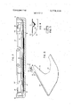
- FIG. 5 is a cross-sectional view of one of the cantilever beams, taken along the-line 5" "5 of Fig. 1.
- the principal operating parts of the shutter are mounted in a box-like panel 10, which is rigidified by integrally formed flanges 12 along all four sides.
- the two blades 14 and 16 stand, one against the other, between the major surface of the panel 10 and a retainer plate 18.
- the plate 18 is rigidly secured to the panel 10 in spaced relation to its major face, leaving adequate space for the blades 14 and 16 to clear-each other.
- the blades are enantiomorphic, but otherwise identical to each other. It will, therefore be sufiicientto describe indetail only the single blade 16 shown in Fig; 3.
- the blade 16 is made of thin sheet material suchas,
- Fig. 1 is fitted into its apex to connect the blade to its'drivingbeam 30.
- the ridge (not separately designated) of the bracket 26 extends normally from the and claimed in my U.S. Pat. No. 3,427,576 through relatively long, structurally shaped, cantilever beams, which magnify the motion ofthe actuator and reduce the sharpness of the rotation that must be accommodated between the swing of the output lever of the actuposure time, andfurther improvement in speed is ex.
- the present invention is not intendedto'be limited to the use of the particular actuator described in the hereinabove identified patent, although thatactuator is presently believed to be the best driving means now known.
- the invention contemplates that the shutter may be driven by any desired means,- even though high speeds may not be achievable.
- FIG. 1 is a front elevational view of a shutter according to the invention with the cover of its mounting .box
- FIG. 2 is a horizontal sectional view taken along the line 2 2 of FIG. .1, with the scale enlarged and distorted to bring out certain details,.especially in respect of thicknesses;
- FIG. 3 is an isometric view of one of blades
- FIG. 4 is a sectional the shutter view taken along the line 4 4 main face of the blade 16, and the sloping sides face the direction of travel of the blade.
- a spring detent 30 (Fig. 1) is fixed to the cover plate 18 for engagement by the bracket 26 at both ends of thetravel of the blade 16.
- the action of the detent in cooperation with the notches 22 are not flat or circularly curved, but are of I generally ogive shape, and the outer ends of the notches are. open, not closed.
- the arrangement very much reduces the chance of interference between the blades relative to blades having simple circular openings. The factor is of importance when the shutter is' driven at high speeds. In preliminary experimental work with blades having circular openings it was found that in high speed operation. a slight buckling of one or both of the blades could cause the edges of the openings to interfere, with consequent damage to the delicate material they are made of.
- the beams 34 and 36 are curved so they will not extend over the opening of the shutter when the shutter is open. They are connected rigidly at their upper ends H to the respective output levers 38 and 40 of the actuator 42. Their lowerends are connected respectively to the blades 16 and 14 through the connecting rods 28. The beams 34 and 36 are urged apart by respective return springs 44 and 45 which serve to drive the shutter closed. when the actuator is deenergized.
- the output levers 38 and 40 are preferably geared to each other through a pair of segment gears 48 and 50,
- the shutter may be easily made as a normally open shutter, that is, open when the actuator 42 is deenergized and closed only when the actuator picks up. This is done simply by suitably shaping the blades '14 and 16 so that they cover the opening when the actuator 42' picks up and clear it when the actuator drops.
- An important advantage of the shutter according to the invention stems from the restriction of the blades to translation only, and relates to the symmetry of the is generally similar in shape to a cats eye.
- a photographic shutter of the kind having a pair of blades reciprocatable in translation and in mutual opposition between afirst position in which the shutter is closed and a second position in which the shutter is open, said shutter comprising: i
- a. a pair of blades of a thin, flexible sheet material, each of said blades including an integral flange extendin'galong one edge thereof for rigidifying it, b. a mounting plate having an aperture, c. a retainer plate having an aperture about the same size as the aperture in said mounting plate, d. means securing said retainer plateto said mounting plate closely spaced and parallel thereto with the apertures of said plates in register with each other,
- each of said blades' is shaped to define a notch of generally ogive shape, the edges of said notchesibeing arranged to move across said aperture during travel of the blades between said positions.
- a shutter according to claim 1 wherein said drive means comprises an electromagnetic actuator.
- said actuator includes output levers that move in rotation only, structural beams are cantilevered on said levers, and connecting rods are pivotted between the distal ends of said beams and respective ones of said blades for driving the blades responsively to motion of said output le-
Landscapes
- Physics & Mathematics (AREA)
- General Physics & Mathematics (AREA)
- Shutters For Cameras (AREA)
Abstract
A photographic shutter having a large aperture (about 2 1/2 inches) that can be driven at relatively high speed by an electromechanical actuator. The shutter has two blades of very thin sheet material that are reciprocated in opposition to each other in translation only. The blades have integrally formed flanges that stiffen them and provide the strength needed to keep them from buckling. The actuator is connected to the blades through relatively long levers to achieve the desired length of travel with adequate allowance for the rotational output motion of the actuator.
Description
United States Patent [19 Vincent, Andrew W."
[ LARGE DIAMETER PHOTOGRAPHIC Y SHUTTER I [76] Inventor: Andrew W. Vincent, 65 Aberdeen St., Rochester, N.Y. 14611 22 Filed: Feb. 9, 1972 [21] Appl. N0.:'224,727
52 U.S.Cl... 95/56,'95/53.E,-95/53 EA,
[58] Field of Search... 95/55, 56, 62, 53 E,
I a ,95/53-EA,5.3 EB
[56] References Cited UNITED STATES PATENTS 1,024,242 4/1912. Athe'rton .L 95/56X- 670,844 3/1901 Cobb. 95/55 X. 335,518 2/1886 Geery eta]... 95/56 1/1953 Simjian [4 1 Nov. 27, 1973 FOREIGN PATENTS OR APPLICATIONS Primary Examiner-'-Monroe H. Hayes Attorney-Hoffman Stone [57] ABSTRACT A photographic shutter having a large aperture (about 2% inches) that'can be driven at relatively high speed by an electromechanical actuator. Theshutter has two blades of very thin sheet material that are reciprocated in opposition to each other in translation only. The blades have integrally formed flanges that stiffen them and provide the strength needed to keep them from buckling. The actuator is connected to the blades through relatively long levers to achieve the desired length of travel with adequate allowance for the rotational output motion of the actuator.
4 Claims, 5 Drawing Figures 1/1929 France 95/56 13,844 10/1887 Great Britain 95/56 PAIENTEDNUYZ'! I975 SHEET 2 [IF 2 T removed;
' of FIG. 3; and
LARGE DIAMETER PHOTOGRAPHIC SHUTTER v ERLEEWMMQBX This invention relates to a novel photographic shutter capable of relatively rapid operation even though it may be-of relatively large size.
The invention arose in the course of efforts to build a shutter having when open an aperture at least 64 mm. in diameter, and which is dependable, rugged, long lasting, and capable of rapid operation. shutter shown and claimed in my previous U.S. Pat. No. 3,595,553 has proven highly successful in sizes of up to about 1 inch diameter aperture. It includes a Pair of shutter blades mounted on beams that are reciprocated in rotation by an electromagnetic actuator. Several practical problems were encountered, however, in attempting to build it in a size much larger than about 1 inch aperture.,The blades had to be of very thin material to minipresent invention, according-to which the shutter in- 5 cludes a pair of very thin blades that are moved in translation only, and that are reinforced against twisting and buckling-by integrally formed flanges. The blades are driven by'an actuator of the kind disclosed FIG. 5 is a cross-sectional view of one of the cantilever beams, taken along the-line 5" "5 of Fig. 1.
The principal operating parts of the shutter are mounted in a box-like panel 10, which is rigidified by integrally formed flanges 12 along all four sides. The two blades 14 and 16 stand, one against the other, between the major surface of the panel 10 and a retainer plate 18. The plate 18 is rigidly secured to the panel 10 in spaced relation to its major face, leaving adequate space for the blades 14 and 16 to clear-each other. The blades are enantiomorphic, but otherwise identical to each other. It will, therefore be sufiicientto describe indetail only the single blade 16 shown in Fig; 3. e The blade 16 is made of thin sheet material suchas,
for example, stainless steel sheet 0.001 inch thick, and
'28 (Fig. 1 is fitted into its apex to connect the blade to its'drivingbeam 30. The ridge (not separately designated) of the bracket 26 extends normally from the and claimed in my U.S. Pat. No. 3,427,576 through relatively long, structurally shaped, cantilever beams, which magnify the motion ofthe actuator and reduce the sharpness of the rotation that must be accommodated between the swing of the output lever of the actuposure time, andfurther improvement in speed is ex.
pected when more experience is gained with it.
The present invention is not intendedto'be limited to the use of the particular actuator described in the hereinabove identified patent, although thatactuator is presently believed to be the best driving means now known. The invention contemplates that the shutter may be driven by any desired means,- even though high speeds may not be achievable.
DETAILED DESCRIPTION A presently preferred embodiment of the invention will now be described in detail in connection with the accompanying drawings, wherein:
FIG. 1 is a front elevational view of a shutter according to the invention with the cover of its mounting .box
FIG. 2 is a horizontal sectional view taken along the line 2 2 of FIG. .1, with the scale enlarged and distorted to bring out certain details,.especially in respect of thicknesses;
. FIG. 3 is an isometric view of one of blades; 1
FIG. 4 is a sectional the shutter view taken along the line 4 4 main face of the blade 16, and the sloping sides face the direction of travel of the blade. A spring detent 30 (Fig. 1) is fixed to the cover plate 18 for engagement by the bracket 26 at both ends of thetravel of the blade 16.
The action of the detent in cooperation with the notches 22 are not flat or circularly curved, but are of I generally ogive shape, and the outer ends of the notches are. open, not closed. The arrangement very much reduces the chance of interference between the blades relative to blades having simple circular openings. The factor is of importance when the shutter is' driven at high speeds. In preliminary experimental work with blades having circular openings it was found that in high speed operation. a slight buckling of one or both of the blades could cause the edges of the openings to interfere, with consequent damage to the delicate material they are made of.
The beams 34 and 36 are curved so they will not extend over the opening of the shutter when the shutter is open. They are connected rigidly at their upper ends H to the respective output levers 38 and 40 of the actuator 42. Their lowerends are connected respectively to the blades 16 and 14 through the connecting rods 28. The beams 34 and 36 are urged apart by respective return springs 44 and 45 which serve to drive the shutter closed. when the actuator is deenergized.
The output levers 38 and 40 are preferably geared to each other through a pair of segment gears 48 and 50,
the shutter, but is desirable when the shutter is held partly open as by a servo arrangement fora time exposure. in the latter case the armature may tend to wander out of level and drive the blades 14 and 16 unequally so that the opening defined by them goes off ,in my previous US. Pat. No. 3,427,576 to provide any of a large number of different operating characteristics. For :example, in some cases it may be desired to optimize operation of a servo arrangement for driving the shutter only partly open and holding it at a predetermined position.-A special curve can be readily calculated for this, taking into account the characteristics of the magnetic circuit of the actuator, the strenth of the return springs 44 and the effective mass of the load. In other cases different curves may be calculated to optimize other features, such as, for example, the opening or closing time of the shutter, or its power consumption.
The shutter may be easily made as a normally open shutter, that is, open when the actuator 42 is deenergized and closed only when the actuator picks up. This is done simply by suitably shaping the blades '14 and 16 so that they cover the opening when the actuator 42' picks up and clear it when the actuator drops.
An important advantage of the shutter according to the invention stems from the restriction of the blades to translation only, and relates to the symmetry of the is generally similar in shape to a cats eye.
What is claimed is: 1
l. A photographic shutter of the kind having a pair of blades reciprocatable in translation and in mutual opposition between afirst position in which the shutter is closed and a second position in which the shutter is open, said shutter comprising: i
a. a pair of blades of a thin, flexible sheet material, each of said blades including an integral flange extendin'galong one edge thereof for rigidifying it, b. a mounting plate having an aperture, c. a retainer plate having an aperture about the same size as the aperture in said mounting plate, d. means securing said retainer plateto said mounting plate closely spaced and parallel thereto with the apertures of said plates in register with each other,
e. said blades lying free and in face to facecontact with each other between said mounting plate and said retainer plate with their flanges extending along one edge of said retainer plate,
f. a retainer bar adjacent to said flanges 'and'on the opposite side thereof from said retainer plate for retaining said flanges-within a predetermined distance frornthe edge of said retainer plate, and
g. drive means for reciprocating said blades in opposition to each other,
' tions parallel to theplane of said mounting plate.
2. A shutter according to claim 1 wherein each of said blades'is shaped to define a notch of generally ogive shape, the edges of said notchesibeing arranged to move across said aperture during travel of the blades between said positions.
3. A shutter according to claim 1 wherein said drive means comprises an electromagnetic actuator.
4. A shutter according to claim 3 wherein said actuator includes output levers that move in rotation only, structural beams are cantilevered on said levers, and connecting rods are pivotted between the distal ends of said beams and respective ones of said blades for driving the blades responsively to motion of said output le-
Claims (4)
1. A photographic shutter of the kind having a pair of blades reciprocatable in translation and in mutual opposition between a first position in which the shutter is closed and a second position in which the shutter is open, said shutter comprising: a. a pair of blades of a thin, flexible sheet material, each of said blades including an integral flange extending along one edge thereof for rigidifying it, b. a mounting plate having an aperture, c. a retainer plate having an aperture about the same size as the aperture in said mounting plate, d. means securing said retainer plate to said mounting plate closely spaced and parallel thereto with the apertures of said plates in register with each other, e. said blades lying free and in face to face contact with each other between said mounting plate and said retainer plate with their flanges extending along one edge of said retainer plate, f. a retainer bar adjacent to said flanges and on the opposite side thereof from said retainer plate for retaining said flanges within a predetermined distance from the edge of said retainer plate, and g. drive means for reciprocating said blades in opposition to each other, h. said retainer bar, together with said retainer plate being the sole guide means for said blades in directions parallel to the plane of said mounting plate.
2. A shutter according to claim 1 wherein each of said blades is shaped to define a notch of generally ogive shape, the edges of said notches being arranged to move across said aperture during travel of the blades between said positions.
3. A shutter according to claim 1 wherein said drive means comprises an electromagnetic actuator.
4. A shutter according to claim 3 wherein said actuator includes output levers that move in rotation only, structural beams are cantilevered on said levers, and connecting rods are pivotted bEtween the distal ends of said beams and respective ones of said blades for driving the blades responsively to motion of said output levers.
Applications Claiming Priority (1)
| Application Number | Priority Date | Filing Date | Title |
|---|---|---|---|
| US22472772A | 1972-02-09 | 1972-02-09 |
Publications (1)
| Publication Number | Publication Date |
|---|---|
| US3774518A true US3774518A (en) | 1973-11-27 |
Family
ID=22841920
Family Applications (1)
| Application Number | Title | Priority Date | Filing Date |
|---|---|---|---|
| US00224727A Expired - Lifetime US3774518A (en) | 1972-02-09 | 1972-02-09 | Large diameter photographic shutter |
Country Status (1)
| Country | Link |
|---|---|
| US (1) | US3774518A (en) |
Cited By (1)
| Publication number | Priority date | Publication date | Assignee | Title |
|---|---|---|---|---|
| US4001844A (en) * | 1974-08-12 | 1977-01-04 | Mcclintock Richard D | Exposure control system |
Citations (5)
| Publication number | Priority date | Publication date | Assignee | Title |
|---|---|---|---|---|
| US335518A (en) * | 1886-02-02 | geeey | ||
| US670844A (en) * | 1900-05-07 | 1901-03-26 | Nathan A Cobb | Photographic shutter. |
| US1024242A (en) * | 1911-04-19 | 1912-04-23 | Herbert Atherton | Advertising-machine. |
| FR656406A (en) * | 1928-06-25 | 1929-05-07 | Workshop camera shutter | |
| US2625857A (en) * | 1949-07-26 | 1953-01-20 | Luther G Simjian | Pose-reflecting photographic apparatus |
-
1972
- 1972-02-09 US US00224727A patent/US3774518A/en not_active Expired - Lifetime
Patent Citations (5)
| Publication number | Priority date | Publication date | Assignee | Title |
|---|---|---|---|---|
| US335518A (en) * | 1886-02-02 | geeey | ||
| US670844A (en) * | 1900-05-07 | 1901-03-26 | Nathan A Cobb | Photographic shutter. |
| US1024242A (en) * | 1911-04-19 | 1912-04-23 | Herbert Atherton | Advertising-machine. |
| FR656406A (en) * | 1928-06-25 | 1929-05-07 | Workshop camera shutter | |
| US2625857A (en) * | 1949-07-26 | 1953-01-20 | Luther G Simjian | Pose-reflecting photographic apparatus |
Cited By (1)
| Publication number | Priority date | Publication date | Assignee | Title |
|---|---|---|---|---|
| US4001844A (en) * | 1974-08-12 | 1977-01-04 | Mcclintock Richard D | Exposure control system |
Similar Documents
| Publication | Publication Date | Title |
|---|---|---|
| US4051499A (en) | Linear motor-driven focal plane shutter | |
| US3967146A (en) | Magnetic motion conversion device | |
| TWI425307B (en) | Focal plane shutter for cameras | |
| JPS5931047B2 (en) | Blades for optical machinery | |
| US3774518A (en) | Large diameter photographic shutter | |
| GB2041990A (en) | Electromagnetic jacquard attachment | |
| GB2113410A (en) | Electromagnetically controlled shutters | |
| US3705370A (en) | Magnetically actuated and restored print hammer | |
| US3474716A (en) | Photographic shutter | |
| US2803181A (en) | Camera shutter having a combined brake and latch | |
| US4040453A (en) | Shuttleless loom of the single or double layer type | |
| GB1407256A (en) | Photographic shutter | |
| US3319748A (en) | Capstan drive | |
| US3381597A (en) | Shutter mechanism for photographic camera | |
| US5619296A (en) | Electromagnetic mechanism for providing a hard stop for moving blade aperture systems | |
| US2878735A (en) | Camera shutter having two sets of blades | |
| GB1381694A (en) | Camera shutter | |
| US1882796A (en) | Card counter | |
| US2896525A (en) | Focal plane shutter | |
| GB1119812A (en) | Improvements in or relating to a weft brake for a loom | |
| US4017167A (en) | Intermittent movement with tandem cams | |
| GB2093489A (en) | Open shed dobbies | |
| GB2147015A (en) | Electronic actuators for knitting machines | |
| US3096700A (en) | Double torsion spring energy-storage photographic shutter | |
| US1840854A (en) | Drive mechanism and artificial bait |